Page is loading ...

1
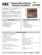
! DISPLAYS INVERSE OF INPUT RATE
! 2 MODELS: 9999 & 999-59
! 0.56" (14.2 mm) HIGH LED DISPLAY (APLPT)
! EASY SELECTION OF DISPLAY & SCALE MULTIPLIER VALUES
! PROGRAMMABLE INPUT CIRCUIT. ACCEPTS OUTPUTS FROM
A WIDE VARIETY OF SENSORS
! DECIMAL MODE SELECT (9999 Model Only)
! POWER-UP SELF-TEST
! 0.02% ACCURACY
! INPUT RATE 0.05 CPS TO 10,000 CPS
! 8 PULSE MOVING WINDOW AVERAGE BELOW 3 CPS
(Selectable)
! NEMA 4/IP65 SEALED FRONT METAL BEZEL
DESCRIPTION
The Apollo Process Time Indicator (Model APLPT) and Module (Model
PBLPT) displays a value representing the time between a beginning and end
point of a process, such as a conveyor oven.
The unit’s display will update inversely in relation to the input signal
frequency. As input frequency increases (representing speed), the
APLPT/PBLPT time display decreases, indicating a reduction in the duration of
process time. For example, the baking time through an oven is inversely
proportional to the conveyor speed.
The APLPT/PBLPT is available in two versions: The Decimal Point version,
APLPT4/PBLPT4, that has 4 digits with different modes that provide for
decimal points; and the chronometer display version, APLPT5/PBLPT5, which
will show as its maximum value, 999-59.
The units have a feature called “moving window average”. This allows one
time disturbances, or irregularly spaced items to be averaged over eight input
pulses, thus keeping display fluctuations to a minimum while still updating the
display on every input pulse. This feature can be enabled or disabled by a side
panel DIP switch.
The units can accommodate magnetic pickups, logic sensors, and NPN open
collector sensors, as well as switch contact closure sensors.
These units have a self-test feature, which checks all the micro-processor and
display driver circuitry at power-up (if enabled). This self-test can also be used
to test display and scale multiplier select DIP switches to make certain all
switches are functioning properly.
Power and input connections are made via a removable terminal strip, located
at the rear of the unit. This strip can accept one #14 AWG wire. DIP switches at
the side of the unit are used to program the input configuration and to set the
scale multiplier value.
The Model APLPT has a sealed metal die-cast bezel which meets NEMA
4/IP65 specifications for wash-down and/or dust, when properly installed. Two
mounting clips are provided for easy installation. The Model APLPT has a 0.56"
high LED display, which is readable to 23 feet (7 M).
SAFETY SUMMARY
All safety related regulations, local codes and instructions that appear in the
manual or on equipment must be observed to ensure personal safety and to
prevent damage to either the instrument or equipment connected to it. If
equipment is used in a manner not specified by the manufacturer, the protection
provided by the equipment may be impaired.
MODELS APLPT - APOLLO PROCESS TIME INDICATOR AND
PBLPT - 4/5 DIGIT MODULE FOR USE WITH THE LARGE DIGIT DISPLAY (LDD)
DIMENSIONS In inches (mm)
Note: Recommended minimum clearance (behind the panel) formounting clip installation is 2.1" (53.4) H x 5.5" (140) W.
CAUTION: Risk of Danger.
Read complete instructions prior to
installation and operation of the unit.
CAUTION:
Risk of electric shock.
Bulletin No. APLPT-J
Drawing No. LP0141
Released 9/05
Tel +1 (717) 767-6511
Fax +1 (717) 764-0839
www.redlion.net
PANEL CUT-OUT

2
SPECIFICATIONS
1. DISPLAY: 4 or 5-digit, 0.56" (14.2 mm) high LED, display. (APLPT)
2. POWER REQUIREMENTS:
APLPT
AC Operation: Available in two voltage ranges. 115 VAC (±10%) or 230
VAC (±10%), 50/60 Hz, 14 VA.
DC Operation: 11 to 14 VDC @ 0.6A max.
PBLPT
AC Operation: Switch selected via the LDD power supply board, 115/230
(±10%), 50/60 Hz, 10 VA for 4-digit, 15 VA for 6-digit (including LDD).
3. SENSOR POWER: +12 VDC, ±25% @ 100 mA max.
4. OPERATING FREQUENCYRANGE: 0.05 pulse/sec. to 10,000 pulse/sec.
Note: When the value to be displayed exceeds the full scale display capacity,
all dashes are displayed. If input rate is too low, the unit will display a zero.
5. ACCURACY AND REPEATABILITY: 0.02%
6. DISPLAYMULTIPLIER INCREMENTTOTAL, SELECTION RANGE:
From 1 to 16,383.
7. SCALE MULTIPLIER VALUES: 1, 10, 100, 1000.
8. DISPLAY UPDATE TIME: The display will update every 0.65 sec. plus one
input pulse when the input pulse rate is 1.54 PPS or higher. When the input
pulse rate is below 1.54 PPS, the display will update on every input pulse.
Note: When the input pulse rate is 3 PPS or lower, the unit will utilize, if
selected, a technique known as a “moving window average”. (This
continually averages the last eight input pulses.)
9. MAXIMUM INPUT VOLTAGE AND CURRENT: When the “SIG. IN”
(Terminal 5) is driven from external signal voltages, maximum allowable
voltage swing is ±50 V peak. Input voltage can be dropped by an external
series resistance that limits input current to ±5 mA. (These ratings are for
S3 “OFF”.)
10. INPUT IMPEDANCE: When S1 and S3 “OFF”, the resistive input
impedance exceeds 1 megohm as long as the “SIG. IN” (Terminal 5) input
voltage is between zero and +12 VDC. Beyond these levels, the high and low
clamping diode will start to conduct, thus decreasing the input impedance.
With S3 “ON” the maximum input voltage to Terminal 5 must be limited to
28 VDC.
11. PARALLELING WITH APOLLO TOTALIZER INPUTS (RLC
standard count input): Apollo Process Time Indicators may be parallel
connected with counters having the RLC standard count input circuitry. These
can operate from a common current sink or source sensor by connecting the
appropriate terminals in common. S3 on the APLPT/PBLPT should be turned
“OFF” since pull-up or pull-down resistors are already present in the counter.
The unit will not add appreciable sensor load with this arrangement.
Note: The APLPT/PBLPT cannot be operated in parallel with standard input
counters when 2-wire proximity sensors are used.
12. INPUT AND POWER CONNECTIONS:
There is a plug-in, compression-type, barrier strip located at the rear of the
unit. This strip can be removed from the rear of the unit for ease of wiring.
After wiring is complete, the connector can be plugged back onto the unit.
13. CERTIFICATIONS AND COMPLIANCES:
SAFETY
IEC 1010-1, EN 61010-1: Safety requirements for electrical equipment for
measurement, control, and laboratory use, Part 1.
IP65 Enclosure rating (Face only), IEC 529
Type 4 Enclosure rating (Face only), UL50
ELECTROMAGNETIC COMPATIBILITY
Notes for APLPT only:
1. Metal bezel of unit connected to earth ground (protective earth) at the
mounting panel.
2. EMI filter placed on the DC power supply, when DC powered: Corcom
#1VB3 or Schaffner #FN610-1/07 (RLC #LFIL0000).
Refer to the EMC Installation Guidelines section of this bulletin for
additional information.
14. ENVIRONMENTAL CONDITIONS:
Operating Temperature Range: 0 to 50°C
Storage Temperature Range: -40 to 70°C
Operating and Storage Humidity: 85% max. relative humidity (non-
condensing) from 0°C to 50°C.
Altitude: Up to 2000 meters
15. CONSTRUCTION: Die-cast metal front bezel with black, high impact
plastic insert. Front panel meets NEMA 4/IP65 requirements for indoor use
when properly installed. Installation Category II, Pollution Degree 2. (Panel
gasket and mounting clips included with unit.)
16. WEIGHT:
APLPT: 1.5 lbs. (0.8 Kg)
PBLPT: 0.4 lbs (0.18 Kg)
Power mains class A
Enclosure class AEN 55011RF interference
Emissions to EN 50081-2
Level 3; 10 V/mENV 50204
150 KHz - 80 MHz
Level 3; 10 V/rms EN 61000-4-6RF conducted interference
Level 3; 2 Kv power
Level 4; 2 Kv I/O
2
EN 61000-4-4Fast transients (burst)
80 MHz - 1 GHz
Level 3; 10 V/m EN 61000-4-3Electromagnetic RF fields
Level 3; 8 Kv air
Level 2; 4 Kv contact
1
EN 61000-4-2Electrostatic discharge
Level 4; 10 A/mEN 61000-4-8Power frequency magnetic fields
200 Hz, 50% duty cycle
Immunity to EN 50082-2
900 MHz ± 5 MHz
Simulation of cordless telephone
BLOCK DIAGRAM

3
INPUT SET-UP
The selection of input set-up is accomplished by the first three DIP switches,
located along the side of the unit. DIP switches 1-3 are used to configure the
input. Each of these switches are discussed below.
Note: Rate type indicators frequently use magnetic pickups for input devices.
Consequently, there are basic differences between counter and rate-indicator
input circuits. In the Model APLPT/PBLPT input circuit, the hysteresis level
is quite small and the bias levels are significantly different to accommodate
both magnetic pickup inputs, as well as the +5 V and higher logic levels. The
APLPT/PBLPT can work with switch contact closures because of the low
count rate capability. S1 should be closed when switch contact closures are
used as inputs to the unit.
S1 - ON [MAG.PKUP.]: Connects a 0.1µf damping input capacitor from input
to common. This capacitor is commonly used with magnetic pickup
inputs and serves to filter out high frequency noise. It can also be used
to filter switch contact closures.
Note: If excessive contact “bounce” or system “noise” is encountered, an
additional external filter capacitor may be necessary. Reed switches,
mercury wetted contacts, snap action limit switches, and silver alloy
relay contacts with wiping action are usually satisfactory for generating
count input signals. Motor starter contacts, tungsten contacts, and brush
type contacts should not be used.
S2 - ON [LOGIC]: Sets the bias reference so that input logic signals trigger
count pulses as they cross a level of approximately +2.5 V.
OFF: Sets the bias reference so that a signal of 150 millivolts or more will
trigger count pulses. This provides the sensitivity required for low speed
magnetic pickup sensors.
Note: Hysteresis for both S2 “ON” and “OFF” conditions is about 25
millivolts. This means the difference between V
IL
and V
IH
with logic
inputs (S2) is almost insignificant and only a very small signal swing
about the 2.5 V bias level will trigger the input.
S3 - ON [NPN O.C.]: Connects a 3.9 K pull-up load resistor for sensors or
circuits with current sink outputs. Sensor output must sink 4 mA @ V
OL
of 1V or less.
SCALE MULTIPLIER SELECTION
The selection of the scale multiplier value is
accomplished by DIP switches 4 and 5. The table
at right shows what combination of switches is
needed to obtain the desired value.
MODE SELECT
(Decimal Point Selection For 9999 unit only)
The selection of a decimal point location using
DIP switches 7 and 8 is shown in the table at right.
(This feature is available only on the
APLPT4/PBLPT4.) In the APLPT4/PBLPT4, the
proper DIP switches must be selected before the
unit is powered up. To change a decimal point
location, the unit must be powered down, the DIP
switches changed, then powered up. The decimal
point will appear as soon as the display reappears.
MOVING WINDOW AVERAGING AND SELF-TEST
DIP switch 6, the S.T./AVG. switch, serves a dual function of disabling or
enabling the “moving window average” (MWA) function and the self-test
function. When the switch is up, MWA and self-test are both disabled. When the
switch is down, MWA and self-test are both enabled.
MOVING WINDOW AVERAGING
This allows the unit to “collect” and average the last eight input pulses which
is continually updated whenever a new pulse occurs. The oldest input data is
discarded and replaced with the new input data.
SELF-TEST
This unit has a built-in self-test feature which can only be activated
immediately after power-up (the unit will not measure time while in self-test).
To activate self-test, set the S.T./AVG. DIP switch (D.S. 6) to the enable
position. Then apply power to the unit. With this test, all digits are cycled
through starting with a string of zeros. This will be shown for about half a
second, then a string of ones will appear for about the same time duration.
Following these, a string of twos and so on, up to nines will be displayed. After
the nines are shown, a string of decimal points will appear. Next, an interlace
pattern of 1, 0, 1, 0, (1, 0,) then 1, 2, 1, 2, (1, 2,) and so on, until all digits from
zero to nine have been displayed.
The next portion of self-test will display four groups of zeros and/or ones.
(The first two digits from the left, in each group, will always show zeros if it is
an APLPT5/PBLPT5. If it is an APLPT4/PBLPT4, the first two digits will be
blank.) In the first group, the third digit represents the 13th (X4096) DIP switch
setting. The fourth and fifth digits show the setting for the Scale Multiplier
select DIP switches. (The fourth position digit represents DIP switch 4 and the
fifth position digit represents DIP switch 5.) The state of these digits coincides
with the table listed under the “Scale Multiplier Selection” section. The last
digit will always show a one for the APLPT5/PBLPT5. But for the
APLPT4/PBLPT4, if both switches 7 and 8 are off, it will then display a zero.
The next three groups are shown
on the right, and correspond to the
DIP switch shown directly above it.
(Note: The first two digits in each
group are always shown as zeros
or blanks.)
The X’s represent a zero or one (depending on the setting of the DIP switch)
in the display. Self-test is automatically exited 8 seconds after the last DIP
switch is changed.
9 10 11 12
(DIP SWITCH)
Group 2: 0 0 X X X X
5 6 7 8
(DIP SWITCH)
Group 3:
0 0 X X X X
1 2 3 4
(DIP SWITCH)
Group 4:
0 0 X X X X
1000
↑ (1)↑ (1)
100
↑ (1)↓ (0)
10
↓ (0)↑ (1)
1
↓ (0)↓ (0)
SCALE
MULTIPLIER
SW 5SW 4
SW 7 SW 8
D.P.
LOCATION
0
↓ (0)↓ (0)
↑ (1) ↓ (0)
0.0
0.00
↑ (1)↓ (0)
↑ (1) ↑ (1)
0.00

4
EMC INSTALLATION GUIDELINES
Although this unit is designed with a high degree of immunity to
ElectroMagnetic Interference (EMI), proper installation and wiring methods
must be followed to ensure compatibility in each application. The type of the
electrical noise, source or coupling method into the unit may be different for
various installations. In extremely high EMI environments, additional measures
may be needed. Cable length, routing and shield termination are very important
and can mean the difference between a successful installation or a troublesome
installation. Listed below are some EMC guidelines for successful installation
in an industrial environment.
1. The unit should be mounted in a metal enclosure, that is properly connected
to protective earth.
a. If the bezel is exposed to high Electro-Static Discharge (ESD) levels, above
4 Kv, it should be connected to protective earth. This can be done by making
sure the metal bezel makes proper contact to the panel cut-out or connecting
the bezel screw with a spade terminal and wire to protective earth.
2. Use shielded (screened) cables for all Signal and Control inputs. The shield
(screen) pigtail connection should be made as short as possible. The
connection point for the shield depends somewhat upon the application.
Listed below are the recommended methods of connecting the shield, in order
of their effectiveness.
a. Connect the shield only at the panel where the unit is mounted to earth
ground (protective earth).
b. Connect the shield to earth ground at both ends of the cable, usually when
the noise source frequency is above 1 MHz.
c. Connect the shield to common of the unit and leave the other end of the
shield unconnected and insulated from earth ground.
3. Never run Signal or Control cables in the same conduit or raceway with AC
power lines, conductors feeding motors, solenoids, SCR controls, and
heaters, etc. The cables should be run in metal conduit that is properly
grounded. This is especially useful in applications where cable runs are long
and portable two-way radios are used in close proximity or if the installation
is near a commercial radio transmitter.
4. Signal or Control cables within an enclosure should be routed as far away as
possible from contactors, control relays, transformers, and other noisy
components.
5. In extremely high EMI environments, the use of external EMI suppression
devices, such as ferrite suppression cores, is effective. Install them on Signal
and Control cables as close to the unit as possible. Loop the cable through the
core several times or use multiple cores on each cable for additional protection.
Install line filters on the power input cable to the unit to suppress power line
interference. Install them near the power entry point of the enclosure. The
following EMI suppression devices (or equivalent) are recommended:
Ferrite Suppression Cores for signal and control cables:
Fair-Rite # 0443167251 (RLC #FCOR0000)
TDK # ZCAT3035-1330A
Steward #28B2029-0A0
Line Filters for input power cables:
Schaffner # FN610-1/07 (RLC #LFIL0000)
Schaffner # FN670-1.8/07
Corcom #1VB3
Corcom #1VR3
Note: Reference manufacturer’s instructions when installing a line filter.
6. Long cable runs are more susceptible to EMI pickup than short cable runs.
Therefore, keep cable runs as short as possible.
WIRING CONNECTIONS
As depicted in the drawing showing the rear view of the Apollo Process Time
Indicator, there is a terminal block where all wiring connections are made. All
conductors should meet voltage and current ratings for each terminal. Also
cabling should conform to appropriate standards of good installation, local
codes and regulations. It is recommended that power supplied to the unit (AC
or DC) be protected by a fuse or circuit breaker. Remove the block for easy
access to the terminal screws. To remove the block, pull from the back of the
block until it slides clear of the terminal block shroud.
Enclosed with the PBLPT module is an adhesive backed label(s) showing the
terminal block pin-out. This label is for wiring reference only, do not use for
specifications. This label should be applied to the appropriate location by the user.
CAUTION: The terminal block should NOT
be removed with power
applied to the unit. The module should not be removed from the
LDD with power applied to the LDD or the module.
INPUT & POWER CONNECTIONS
Primary AC power is connected to Terminals 1 and 2 (marked A.C. Power,
located on the left-hand side of the block). For best results, the AC power should
be relatively “clean” and within the specified ±10% variation limit. Drawing
power from heavily loaded circuits or from circuits that also power loads that
cycle on and off should be avoided.
Terminal 3 is the “DC” (+12 V) terminal. This terminal is for sensor supply
and can provide up to 100 mA of current. An external +11 V to +14 VDC can
also be applied to this terminal to power the unit in the absence of A.C. power.
Terminal 4 is the “COMM.” (common) terminal, which is the common line to
which the sensor and other input commons are connected. Terminal 5 is the
“SIG. IN” (signal in) terminal. When the signal at this terminal goes low, a
count will be registered in the unit. (See “Input Ratings” under
“Specifications” section.)
REAR PANEL DIP SWITCHES
As can be seen from the rear of the unit, there is a row of 14 DIP switches
located beside the input and power terminal block. All of these DIP switches are
Display Multiplier Increment Total (DMIT) switches. When the switch is “ON”,
it will multiply the measured time between input pulses by the display multiplier
it represents.

5
INSTALLATION ENVIRONMENT
The unit should be installed in a location that does not exceed the maximum
operating temperature and provides good air circulation. Placing the unit near
devices that generate excessive heat should be avoided.
The bezel should be cleaned only with a soft cloth and neutral soap product.
Do NOT use solvents.
Continuous exposure to direct sunlight may accelerate the aging process of
the bezel.
INSTALLATION
PBLPT installation information is contained in the LDD Bulletin. Refer to
that bulletin for instructions on installing the module.
The unit meets NEMA 4/IP65 requirements for indoor use, when properly
installed. The Apollo Indicators are intended to be mounted into an enclosed
panel with a gasket to provide a water-tight seal. Two mounting clips and
screws are provided for easy installation. Consideration should be given to the
thickness of the panel. A panel which is too thin may distort and not provide a
water-tight seal. (Recommended minimum panel thickness is 1/8".)
After the panel cut-out has been completed and deburred, carefully slide the
panel gasket over the rear of the unit to the back of the bezel. Insert the unit into
the panel. As depicted in the drawing, install the screws into the narrow end of
the mounting clips.
Thread the screws into the clips until the pointed end just protrudes through
the other side. Install each of the mounting clips by inserting the wide lip of the
clips into the wide end of the hole,
located on either side of the case. Then
snap the clip onto the case.
Tighten the screws evenly to apply
uniform compression, thus providing a
water-tight seal.
CAUTION: Only minimum pressure is
required to seal panel. Do NOT
overtighten screws.
CONNECTIONS & CONFIGURATION SWITCH SET-UP FOR VARIOUS SENSOR OUTPUTS
MAGNETIC PICKUPS SENSORS WITH CURRENT SINK OUTPUT (NPN O.C.)
[Includes ASTC, LMPC, PSAC, RPGC, (RPGB, RPGH) * , LSC]
SENSORS WITH CURRENT SOURCE OUTPUT (PNP O.C.)
TWO WIRE PROXIMITY SENSORS SENSORS WITH A.C. INPUTS FROM TACH. INPUT FROM CMOS & OTHER INPUT FROM TTL
-EF OUTPUT GENERATORS, INVERTERS, BI-POLAR OUTPUTS
ETC.
INPUT FROM CONTACT CLOSURES
Use 2-wire shielded cable for magnetic pickup signal leads.

6
BREAD BAKING APPLICATION
Loaves of bread are being baked in a continuous baking oven. It has been
determined that 10 minutes and 30 seconds is normally required for a loaf to
progress through the oven (this provides enough time for the loaves to be
baked). An RPGC, with 60 PPR, is attached to one of the conveyor belt shafts.
When the conveyor belt moves at the 10 min.-30 sec. rate, the shaft turns at 35
RPM. An APLPT5 is used to display the value of 10 min. and 30 sec. Using
the formula, the required DIP switch settings are obtained.
PPS = 60 PPR x 35 RPM = 2100 PPM ÷ 60 DMIT = D.R. x P.P.S.
PPS = 35 = 630 x 35
DR = 10 min. & 30 sec. (convert min. to sec.) DMIT = 22,050
DR = (10 min. x 60) + 30 DMIT = 22,050 ÷ 10*
DR = 630 DMIT = 2,205
* A scale multiplier of 10 is selected because a value greater than 16,383 is
required.
DIP switch 12 . . . . . - 2048 Needed = 157
DIP switch 8 . . . . . - 128 Needed = 29
DIP switch 5 . . . . . - 16 Needed = 13
DIP switch 4 . . . . . - 8 Needed = 5
DIP switch 3 . . . . . - 4 Needed = 1
DIP switch 1 . . . . . - 1
Therefore, DIP switches 1, 3, 4, 5, 8, and 12 must be turned “ON”. Also, DIP
switch 4 on the side panel must be set “ON” to get a multiplier value of 10.
DISPLAY MULTIPLIER SELECTION PROCEDURE
The APLPT/PBLPT has a Display Multiplier Selection range from 1 to
16,383. For the minimum scaled reading, the X1 DIP switch would be set to
“ON”. For the maximum scaled reading (16,383 times the measured time
between input pulses), all of the rear panel DMIT DIPswitches would be turned
“ON”. Therefore, a specific Display Multiplier Increment Total is achieved by
adding up the appropriate individual display multiplier values.
Also available are four scale multiplier (SM) values of X1, X10, X100, and
X1000, which are controlled by DIP switches 4 and 5 on the side of the unit.
The X10, X100, and X1000 scale multiplier values can be used when the
required DMIT exceeds 16,383. Note: Always use the smallest SM value
possible. Below is a formula to compute the DMIT. Note: This same basic
formula applies to all units. However, for the APLPT5/PBLPT5 the D.R. must
be converted to a base unit of measurement.
DMIT = D.R. x P.P.S.
DMIT = Display Multiplier Increment Total
DR = Desired Reading (In hrs., mins., sec., days, etc.)
PPS = Pulses Per Second (input)
NOTES:
1. For the APLPT5/PBLPT5, the display value must be converted to its base
units. To do this, multiply the value to the left of the dash by 60 and add it to
the value to the right of the dash.
2. If the required DMIT value exceeds 16,383, then a scale multiplier value
greater than 1 will be needed. But always use the smallest SM possible.
EXAMPLE 1 (for APLPT4):
DESIRED READING = 18 minutes
PULSES PER SECOND = 450 pulses per second
DMIT = 18 x 450 P.P.S.
= 8100
DMIT = 8100
The required DMIT does not exceed 16,383, therefore, use a value of 1 for
the S.M.
The appropriate display multiplier switches (which together add up to 8100),
are then set to “ON”. Start by selecting the first increment which is greater than
half the desired DMIT, and add subsequent increments that are more than half
the difference needed.
DMIT = 8100
DIP switch 13 . . . . . - 4096 Needed = 4004
DIP switch 12 . . . . . - 2048 Needed = 1956
DIP switch 11 . . . . . - 1024 Needed = 932
DIP switch 10 . . . . . - 512 Needed = 420
DIP switch 9 . . . . . - 256 Needed = 164
DIP switch 8 . . . . . - 128 Needed = 36
DIP switch 6 . . . . . - 32 Needed = 4
DIP switch 3 . . . . . - 4
Therefore, DIP switches 3, 6, 8, 9, 10, 11, 12, and 13 would be set to “ON”.
Note: If the desired reading is 18.0, the SM can be set for a value of 10. (To get
the D.P. required, the unit must be powered down, then switches 7 and 8 set
appropriately, then powered back up.)
EXAMPLE 2 (for APLPT5):
DESIRED READING = 2 hours and 23 minutes (2-23)
PULSES PER SECOND = 230 pulses per second
First convert the D.R. to its base units.
D.R. = 2 (hours) x 60 + 23 DMIT = 143 x 230 PPS
= 120 + 23 = 32,890
= 143 DMIT = 32,890 ÷ 10*
DMIT = 3,289
* Since the required DMIT does exceed 16,383, a value of 10 is used for the S.M.
DMIT = 3289
DIP switch 12 . . . . . - 2048 Needed = 1241
DIP switch 11 . . . . . - 1024 Needed = 217
DIP switch 8 . . . . . - 128 Needed = 89
DIP switch 7 . . . . . - 64 Needed = 25
DIP switch 5 . . . . . - 16 Needed = 9
DIP switch 4 . . . . . - 8 Needed = 1
DIP switch 1 . . . . . - 1
Therefore, DIP switches 1, 4, 5, 7, 8, 11, and 12 would be set to “ON” for a
display of 2-23. DIP switch 4 on the side panel must be set to “ON” to obtain
the S.M. value of 10.

7
115 VAC230 VAC
APLPT500
APLPT400
APLPT510
APLPT410
Apollo 5-Digit Process Time Indicator
Apollo 4-Digit Process Time Indicator
For more information on Pricing, Enclosures & Panel Mount Kits refer to the RLC Catalog or
contact your local RLC distributor.
APLPT
DESCRIPTIONMODEL NO.
PART NUMBERS FOR AVAILABLE
SUPPLY VOLTAGES
ORDERING INFORMATION
PBLPT500
PBLPT400
115/230 VAC
Apollo 5-Digit Process Time Module for use
with the 6 digit Large Digit Display
Apollo 4-Digit Process Time Module for use
with the 4 digit Large Digit Display
PBLPT *
PART NUMBERS
DESCRIPTIONMODEL NO.
PERSONALITY MODULE
* Requires an LDD for use.
TROUBLESHOOTING
For further technical assistance, contact technical support at the appropriate
company numbers listed.

LIMITED WARRANTY
The Company warrants the products it manufactures against defects in materials and workmanship
for a period limited to two years from the date of shipment, provided the products have been stored,
handled, installed, and used under proper conditions. The Company’s liability under this limited
warranty shall extend only to the repair or replacement of a defective product, at The Company’s
option. The Company disclaims all liability for any affirmation, promise or representation with
respect to the products.
The customer agrees to hold Red Lion Controls harmless from, defend, and indemnify RLC against
damages, claims, and expenses arising out of subsequent sales of RLC products or products
containing components manufactured by RLC and based upon personal injuries, deaths, property
damage, lost profits, and other matters which Buyer, its employees, or sub-contractors are or may be
to any extent liable, including without limitation penalties imposed by the Consumer Product Safety
Act (P.L. 92-573) and liability imposed upon any person pursuant to the Magnuson-Moss Warranty
Act (P.L. 93-637), as now in effect or as amended hereafter.
No warranties expressed or implied are created with respect to The Company’s products except those
expressly contained herein. The Customer acknowledges the disclaimers and limitations contained
herein and relies on no other warranties or affirmations.
Red Lion Controls
20 Willow Springs Circle
York PA 17402
Tel +1 (717) 767-6511
Fax +1 (717) 764-0839
Red Lion Controls AP
31, Kaki Bukit Road 3,
#06-04/05 TechLink
Singapore 417818
Tel +65 6744-6613
Fax +65 6743-3360
Red Lion Controls BV
Basicweg 11b
NL - 3821 BR Amersfoort
Tel +31 (0) 334 723 225
Fax +31 (0) 334 893 793
/