System Sensor BEAM1224 and BEAM1224S User manual
- Type
- User manual

1 I56-2294-007R
06-10
INSTALLATION AND MAINTENANCE INSTRUCTIONS
BEAM1224, BEAM1224S
Single-ended Reected Type
Projected Beam Smoke Detector
3825 Ohio Avenue, St. Charles, Illinois 60174
800/736-7672, FAX: 630/377-6495
www.systemsensor.com
SPECIFICATIONS
GENERAL
Range: 16 to 230 Feet (5 to 70m); 230 to 328 Feet (70 to 100m) using optional accessory BEAMLRK
Sensitivity: 25% to 50% Total Obscuration in 6 levels
Level 1 = 25%
Level 2 = 30%
Level 3 = 40%
Level 4 = 50%
Level 5 = 30% to 50% (Acclimate)
Level 6 = 40% to 50% (Acclimate)
Spacing: 30 to 60 Feet (9.1 to 18.3m)
Response Time: ALARM - 20 seconds typical; TROUBLE - 30 seconds typical
Trouble Conditions: Beam Blockage (96% or More Obscuration)
Improper Initial Alignment
Self-compensation limit reached (service needed)
In Alignment mode
Test/Reset Features: Integral Sensitivity Test Filter (BEAM1224S only)
Sensitivity Filter (Incremental scale on reflector)
Local Alarm Test Switch
Local Alarm Reset Switch
Remote Test and Reset Switch Capability
Indicators: ALARM - Remote Output, Local LED (red)
TROUBLE - Remote Output, Local LED (yellow), Blink Pattern Indicates Trouble Diagnostics
NORMAL OPERATION - Local LED (flashing green once every 5 sec.)
ALIGNMENT AIDS - Optical Gunsight (coarse adjustment), 00 to 99 Digital Display (fine adjustment)
RELAYS - Alarm; Trouble
SENSITIVITY - Digital Display Readout in Percent Obscuration
ENVIRONMENTAL
Temperature: –22°F to 131°F (–30°C to 55°C); NOTE: For applications below 32°F (0°C), see Special Applications on page 2
Humidity: 10% to 93% RH Non-condensing
MECHANICAL
Shipping Weight: Complete unit: 3.9 lbs. (1.77 kg)
Shipping Size: 15˝×10.5˝×6.5˝ (381mm × 267mm × 165mm)
Mounting: Wall only without optional accessories
Wiring: Plug-in Terminal Blocks (12 to 22AWG)
Adjustment Angle: ±10° Horizontal and Vertical
Paintable Trim Ring: May be painted using enamel or acrylic type paints
ELECTRICAL
Voltage: 10.2 to 32 VDC (BEAM1224); 15 to 32 VDC (BEAM1224S)
Maximum Ripple Voltage: 6.0 volts (Peak-to-peak); NOTE: ripple must not fall below minimum operating voltage specification
Current (24 VDC): Avg. Standby - 17mA Max.
Avg. Alarm - 38.5mA Max.
Avg. Trouble - 8.5mA Max.
Avg. Alignment - 28mA Max.
Current (Test Mode, BEAM1224S only): Peak Test- 500mA Max.
Relay Contacts: 0.5A at 30 VDC
Reset Time: 0.3 Seconds Max.
Start-up Time (after 2 min. reset): 60 sec. Max.
Alarm Verification Time: 5 sec. Max.
Remote Output (Alarm & Trouble): VOLTAGE - 15 to 32 VDC; NOTE: Output voltage same as device input voltage
CURRENT - 15mA maximum; 6mA minimum; NOTE: Output current is limited by 2.2Kohm resistor
I56-2294-007R
BEFORE INSTALLING
Please thoroughly read this manual and applicable sections of System Sensor’s
Single-Ended Reflected Beam Detector Application Guide (BMAG240). This
manual is available online at www.systemsensor.com.
GENERAL DESCRIPTION
System Sensor Model BEAM1224/BEAM1224S is a long range projected beam
smoke detector designed to provide open area protection. It is to be used
with UL-listed, separately supplied power (4-wire) control panels only. The
detector consists of a transmitter/receiver unit and a reflector. Smoke entering
the area between the transmitter/receiver and reflector causes a reduction in
signal. When the obscuration reaches alarm thresholds (chosen at the trans
-
mitter/receiver unit), the detector generates an alarm signal. Complete block-
age of the beam causes a trouble signal. Slow changes in obscuration due to
a build up of dirt or dust on the lens of the detector are compensated for by

2 I56-2294-007R
06-10
a microcontroller that continuously monitors the signal strength and periodi-
cally updates the alarm and trouble thresholds. When the self-compensation
circuit reaches its limit, the detector generates a trouble signal, indicating the
need for service.
Three LEDs on the detector indicate the current status: a red LED for alarm, a
yellow LED for trouble, and a blinking green LED for standby operation. The
alarm signal latches and can be reset by a momentary power interruption, by
using the remote reset input to the detector if using the remote test/reset sta-
tion model RTS451, or with the local reset button located on the detector. The
local reset button is accessible by removing the outer paintable trim ring. The
yellow LED will blink in specific patterns to provide a diagnostic aid when
diagnosing the cause of a trouble signal. It will also blink the amount of drift
compensation that has been used at the conclusion of the test. Trouble signals
automatically reset upon removing the cause of trouble. Red and yellow LEDs
can be remotely connected to the remote Alarm and Trouble outputs. These
outputs mimic the functions of the detector’s red and yellow LEDs. In addition
to these indicators, there is a dual digital display that reads 00 to 99. This dis-
play is used to indicate the signal strength of the beam in alignment mode and
to indicate the sensitivity setting of the detector in percent obscuration when
setting the sensitivity of the detector. No additional equipment is needed for
alignment of the beam.
Each detector contains one Form A (normally open) contact for alarm signals
and one Form B (normally closed) contact for trouble signals. The trouble
contact will open if power is removed from the detector. Thus, an additional
EOL power supervision relay is not necessary. The trouble contacts from all
the beam detectors on one initiating circuit must be connected after the last
indicating device on the loop. This prevents a single beam detector in trouble
from disabling other initiating devices on the same loop.
SPECIAL APPLICATIONS
Due to the inherent capabilities of projected type beam detectors they are
often installed in locations where spot-type detection is impractical. Projected
type beam smoke detectors are ideally suited for environmental conditions
that might include high ceilings, dusty and dirty environments, or environ-
ments that experience temperature extremes. Often these conditions present
special problems for the installation of spot-type detectors and even greater
problems for their proper maintenance. Due to the inherent flexibility of
mounting locations and large coverage area of projected type beam detectors
often the conditions above can be addressed or minimized.
Some examples of applications for beam detectors might include freezers, air-
craft hangars, cold storage warehouses, shipping warehouses, enclosed park-
ing facilities, sporting arenas and stadiums, concert halls, barns, or stables.
Some of these environments might be considered too hostile for spot-type
smoke detectors. If the environment is considered to be hostile then the colder
alarm threshold settings should be used.
Before installing the transmitter/receiver unit or reflector in these types of
applications special consideration should be given to ensure proper operation
of the beam detector. The beam detector should not be installed in environ-
ments where heavy condensation or icing is likely. Condensation or icing of
the reflector surface or the outer surface of the transmitter/receiver unit will
obscure the light beam resulting in a false alarm. If elevated humidity levels
and rapidly changing temperatures can be expected then condensation will
likely form and the application should not be considered acceptable for the
beam detector. The beam detector should not be installed in locations where
the transmitter/receiver unit, the reflector, or the optical pathway between
them may be exposed to outdoor conditions such as rain, snow, sleet, or fog.
These conditions will impair the proper operation of the detector and must
be avoided.
APPROVED ACCESSORIES
The following accessories can be purchased separately for use with this
beam detector.
BEAMLRK
The BEAMLRK allows System Sensor reflected beam detectors to be installed
at separations between 230 and 328 feet (70 to 100 meters). At these distances,
four 8˝×8˝ reflectors must be used to provide enough reflected infrared light.
This kit includes 3 additional reflectors with new test scale legends. The re-
flector included with the transmitter/receiver unit is the fourth reflector to be
used. This kit is not compatible with the multi-mount kit (BEAMMMK).
BEAMMMK
The BEAMMMK allows System Sensor reflected beam detectors and reflec-
tors to be mounted to either a vertical wall or the ceiling. The kit allows for
additional alignment range in cases where the detector and reflector cannot
be mounted within 10° of each other. The kit includes the hardware neces-
sary to mount either a single transmitter/receiver unit or a single reflector.
(To mount the transmitter/receiver the surface mount kit, BEAMSMK, must
also be used). If the transmitter/receiver and the reflector require additional
alignment range two kits are required. The kit is not compatible with the long-
range reflector kit (BEAMLRK).
BEAMSMK
The BEAMSMK allows System Sensor reflected beam detectors to be mounted
when surface wiring is used. This kit must be used when mounting the trans-
mitter/receiver unit with the multi-mount kit (BEAMMMK).
6500-MMK
The 6500-MMK provides a heavy-duty multi-mount bracket for installations
prone to building movement or vibration. It offers similar tilt and swivel flex-
ibility found on the BEAMMMK. (To mount the transmitter/receiver to the
6500-MMK, the surface mount kit, 6500-SMK, must be used).
6500-SMK
The 6500-SMK allows the transmitter/receiver to be mounted to the 6500-
MMK heavy duty multi-mount kit.
BEAMHK
The BEAMHK allows the transmitter/receiver unit to operate in environments
prone to the formation of condensation. Condensation forming on the beam
detector unit may result in trouble or false alarm conditions. BEAMHK will
lessen the likelihood of condensation by maintaining the unit at a temperature
that is slightly higher than the surrounding air. Please refer to the BEAMHK
installation manual for operation instructions.
BEAMHKR
The BEAMHKR allows the reflector to operate in environments prone to the
formation of condensation. Condensation forming on the reflector may result
in trouble or false alarm conditions. BEAMHKR will lessen the likelihood of
condensation by maintaining the reflector at a temperature that is slightly
higher than surrounding air. The kit requires a 24V power supply. When used
with the long-range reflector kit (BEAMLKR), it is necessary to purchase and
install four BEAMHKR kits. Please refer to the BEAMHKR installation manual
for operation instructions.
RTS451/KEY or RTS151/KEY
The remote test accessory allows for the beam detector to be tested remotely.
The test accessory provides test and reset functions and green and red LED’s
that mimic the LED’s on the detector.
PARTS LIST
Description Quantity
Transmitter/Receiver Unit .....................................1
Paintable Trim Ring .........................................1
Reflector .................................................1
Plug-in Terminal Blocks ......................................4
Instruction Manual .........................................1
Orange Paper Sheet .........................................1
PARTS DIAGRAM (NOT TO SCALE):
TERMINAL BLOCK PAINTABLE TRIM RING
C1049-00

3 I56-2294-007R
06-10
DETECTOR PLACEMENT
This section of the manual discusses the placement of projected beam detec-
tors. Though this information is based upon industry expertise, it is intended
to be used only as a technical guide. Always comply with the requirements of
applicable codes and standards such as, NFPA 72, National Fire Alarm Code,
as well as directives of the Authority Having Jurisdiction (AHJ). For general
information on the placement of detectors, read System Sensor’s Projected
Beam Detector Application Guide.
Projected beam detectors are usually located with their beams parallel to the
ceiling. However, they can be mounted vertically or at any angle to protect the
area involved. Since beam detectors sense the smoke buildup over a distance,
they are ideal for locations with high ceilings. They can also be mounted on a
wall or ceiling below the level of a spot type detector, reducing the effects of
air stratification. Some typical locations would include large areas with high
ceilings such as atriums, warehouses, and factories.
NOTE: Projected beam smoke detectors should always be mounted to stable
mounting surfaces. See the MOUNTING LOCATION section for details.
Some fire codes specify spacing on a given center-to-center distance between
detectors under ideal conditions. This spacing is based on rooms with smooth
ceilings and no physical obstructions between the contents being protected
and the detectors. Moreover, they are also based on a maximum ceiling
height, and on the assumption that the value and the combustible nature of
the contents of the room being protected do not warrant greater protection or
closer spacing.
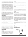
In a room with a smooth ceiling, detectors should be spaced horizontally be-
tween 30 and 60 feet (9.1 to 18.3m). One-half that spacing between the beam
and the sidewall may be used as a guide. See Figure 1. The beam detector
can be mounted with the transmitter/receiver on one wall and the reflector
on the opposite wall, or both suspended from the ceiling, or any wall/ceiling
combination. In the case of the ceiling mount, the distance from the end walls
should not exceed one-quarter of the selected spacing (7.5 ft. [2.3m] maxi-
mum if the spacing is 30 ft. [9.1m] ). See Figure 2.
FIGURE 1. SPACING FOR SMOOTH CEILING (SIDE VIEW):
1
/
2
S S
12 IN. MIN.
(0.3M)
30’
(9.1M) MAX
TO FIRST
DETECTORS
WALL
10’ (3.0M)
MIN.
TYPICAL
C0254-02
FIGURE 2. SPACING FOR SMOOTH CEILING (TOP VIEW):
16 FT. (5M) MINIMUM
328 FT. (100M) MAXIMUM
Tx/Rx REFLECTOR
S
Tx/Rx REFLECTOR
1
/
2
S MAXIMUM
1
/
4
S
MAX.
C0255-00
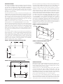
In the case of peaked or sloped ceilings, codes may specify spacing of detectors
by using horizontal spacing from the peak of the roof or ceiling. Figures 3 and
4 show the spacing for both the shed type and peaked type sloped ceilings.
On smooth ceilings, beam smoke detectors should generally be mounted a
minimum of 12 inches (0.3m) from the ceiling or beneath structural obstruc-
tions such as joists, ducts, etc. See Figure 1 In addition, beam smoke detectors
should be mounted vertically at least 10 feet (3.0 m) from the floor to avoid
common obstructions from normal building usage. In many cases, however,
the location and sensitivity of the detectors shall be the result of an engineer-
ing evaluation that includes the following: ceiling heights above 30 feet (9.1
m) – refer to System Sensor’s Single-Ended Reflected Beam Detector Applica-
tion Guide (BMAG240) for more information regarding the effects of stratifica-
tion, structural features, size and shape of the room and bays, occupancy and
uses of the area, ceiling height, ceiling shape, surface and obstructions, venti-
lation, ambient environment, burning characteristics of the combustible mate-
rials present, and the configuration of the contents in the area to be protected.
As a general rule, reflective objects such as ductwork or windows should be a
minimum of 15 inches (38.1cm) from the path of the beam.
FIGURE 3. SLOPED CEILING (SHED TYPE):
S
3 FT.
(0.9M)MAX.
S
1
/
2
S MAX.
Tx/Rx
REFLECTOR
C0256-00
FIGURE 4. SLOPED CEILING (PEAKED TYPE):
1
/
2
S S
S
1
/
2
S
3 FT. (0.9M)
MAX.
3 FT. (0.9M)
MAX.
MOUNT SPOT DETECTOR
ANYWHERE IN THIS
AREA AT LEAST 4 IN. (100 mm)
VERTICALLY FROM PEAK
Tx/Rx
REFLECTOR
C0257-04
MOUNTING LOCATIONS
Beam detectors require a stable mounting surface for proper operation. A sur-
face that moves, shifts, vibrates, or warps over time will cause false alarm or
trouble conditions. Initial selection of a proper mounting surface will elimi-
nate false alarms and nuisance trouble signals.
Mount the detector on a stable mounting surface, such as brick, concrete,
a sturdy load-bearing wall, support column, structural beam, or other sur-
face that is not expected to experience vibration or movement over time. DO
NOT MOUNT the beam detector on corrugated metal walls, sheet metal walls,
external building sheathing, external siding, suspended ceilings, steel web
trusses, rafters, nonstructural beam, joists, or other such surfaces.
In cases where only one stable mounting surface as defined above can be
used, the transmitter/receiver unit should be mounted to the stable surface
and the reflector should be mounted to the less stable surface. The reflector has
a much greater tolerance for the unstable mounting locations defined above.

4 I56-2294-007R
06-10
MOUNTING INSTRUCTIONS
The transmitter/receiver unit may be mounted over a recessed junction box.
The cavity behind the detector is then used for routing of the wiring from the
junction box to the terminal blocks on the detector. The transmitter/receiver
unit should be mounted to the wall such that unit covers the recessed junc-
tion box in the wall completely. If the junction box is not recessed then you
may use the surface mount kit (BEAMSMK). See the BEAMSMK installation
instructions for surface mounting instructions. The transmitter/receiver unit
can be mounted to the wall using the supplied drilling template (see Appendix
II). The detector base has 4 primary mounting keyholes, one in each corner of
the base. All four hole locations should be used to provide a secure mounting.
The outer housing of the beam detector is held to the base using four screws.
In order to mount the detector you must remove the outer housing first.
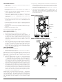
The reflector can be mounted to the wall using the supplied drilling template
see (Appendix III). The reflector has 4 mounting holes, one in each corner.
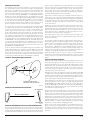
All four hole locations should be used to provide a secure mounting. The
reflector must be mounted such that it is within 10° in both the X and Y
planes of the transmitter/receiver unit. See Figure 5a. The reflector must also
be mounted such that the plane of the reflector is perpendicular to the optical
line of sight to the transmitter/receiver unit. The maximum tolerance for non-
perpendicular mounting locations is 10°. See Figure 5b. If the reflector cannot
be mounted within 10° of the transmitter/receiver unit then the multi-mount
kit (BEAMMMK) or the heavy-duty multi-mount kit (6500-MMK) may be used
to provide greater angular adjustment of the transmitter/receiver unit. If the
perpendicular plane of the reflector cannot be mounted within 10° of the op-
tical line of sight then the multi-mount kit can be used for the reflector. See
BEAMMMK or 6500-MMK instructions.
To aid in locating the reflector in the alignment mirror at long distances a an
orange, adhesive-backed sheet of paper is provided. Remove the protective
backing from the orange paper. Temporarily affix the orange paper next to the
reflector. The location of the paper is not critical. It may be placed anywhere
near the reflector as long as it not covering the reflective surface of the reflec-
tor. This paper should be removed once the installation is completed.
FIGURE 5A. REFLECTOR MOUNTING GUIDELINES:
WALL
REFLECTOR
ACCEPTABLE MOUNTING
LOCATIONS FOR REFLECTOR
X
Y
10°
10°
C0258-01
FIGURE 5B. REFLECTOR MOUNTING GUIDELINES
10° MAXIMUM
OPTICAL LINE OF SIGHT
REFLECTOR
C0259-00
MOUNTING CONSIDERATIONS FOR SINGLE ENDED BEAM DETECTORS:
There must be a permanent clear line of vision between the detector and the
reflector. Reflective objects must not be near the line of vision between the
detector and reflector. Reflective objects too near to the line of sight can reflect
the light beam from the transmitter to the receiver. If this occurs, the detector
will not be able to distinguish these reflections from those of the reflector and
the protected space will be compromised. Reflective objects such as ductwork
or windows should be a minimum of 15 inches (38.1cm) from the path of the
beam. In cases where reflective objects cannot be avoided, the complete re
-
flector blockage test can be used to determine if the installation is acceptable.
See Testing and Maintenance Section of this manual.
Light sources of extreme intensity such as sunlight and halogen lamps, if di-
rected at the receiver, can cause a dramatic signal change resulting in fault
and alarm signals. To prevent this problem direct sunlight into the transmitter/
receiver unit should be avoided. There should be a minimum of 10° between
the pathway of the light source and detector and the line of sight between
detector and reflector.
Operation of the detector through panes of glass should be avoided. Since
single ended beam detectors operate on a reflection principle, a pane of glass
perpendicular to the line of sight between the detector and the reflector can
reflect the light beam from the transmitter to the receiver. If this occurs, the
detector will not be able to distinguish these reflections from those of the re-
flector and the protected space will be compromised.
Panes of glass will also absorb some of the light as it passes through it. This
absorption of light will reduce the acceptable installed distance between the
detector and the reflector.
In cases where operation through panes of glass cannot be avoided some spe-
cific installation practices can help to minimize the effects of the glass. These
practices include: avoid penetration of multiple panes of glass, position the
glass so that it is not perpendicular to the line of sight between the detector
and the reflector, (A minimum of 10° off perpendicular should be considered),
and make certain that the glass is smooth, clear and mounted securely. The
complete reflector blockage test can be used to determine if the installation is
acceptable. See Testing and Maintenance Section of this manual.
Where high ceilings (in excess of 30 feet or 9.1 meters) are present additional
beam smoke detectors mounted at multiple heights may be required to detect
smoke at lower levels. See the Detector Placement section in this installation
manual.
WIRING INSTALLATION GUIDELINES
Always install all wiring in compliance with the National Electrical Code, and/
or the applicable local codes, and any special requirements of the local au-
thority having jurisdiction. Proper wire gauges and suitable means for strain
relief should be used. The conductors used to connect beam smoke detectors
to control panels and accessory devices should be color-coded to reduce the
likelihood of wiring errors. Improper connections can prevent a system from
responding properly in the event of a fire.
Installation wire used for the beam detector shall be no smaller than 22 AWG
(1.0 mm2). For best system performance, all wiring should be twisted pair and
installed in separate grounded conduit. Do NOT mix fire system wiring in the
same conduit as any other electrical wiring. Shielded cable may be used to
provide additional protection against electrical interference.
When installing the beam smoke detector in applications where the head
unit will be mounted to either a wall or the ceiling using the multi-mount
kits(BEAMMMK or 6500-MMK) flexible conduit will be used. The surface
mount kits (BEAMSMK or 6500-SMK) and multi-mount kits (BEAMMMK or
6500-MMK) must be installed with the cable before wring the unit, according
to the instructions supplied with the kit.
When the detector has been mounted over a recessed junction box, all wiring
should be routed out of the box and behind the detector to the bottom of the
detector where the terminal blocks are located. When installing the wiring
in the junction box be sure to leave enough wire in the box to connect to the
terminal blocks. (Approximately 9˝ [23cm) of wire outside of the junction box
will be required for proper installation). All wiring to the detector is done via
pluggable terminal blocks. In order to properly make electrical connections
strip approximately
1
/4˝ (6mm) of insulation from the end of the wire, sliding
the bare end of the wire under the clamping plate screw.
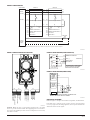
Figure 7 shows all the wiring connections to the transmitter/receiver unit.
Figure 6 shows the proper wiring diagram for either class A or class B opera-
tion. Figure 8 shows the connections that are necessary when using one of the
optional remote test stations. Figure 9 shows the remote outputs for trouble
and alarm.

5 I56-2294-007R
06-10
FIGURE 7. WIRING CONNECTIONS AT DETECTOR:
POWER OUT (–)
POWER OUT (+)
POWER IN (–)
POWER IN (+)
RESET I NPUT
TEST INPUT
AUX (–)
REMOTE ALARM OUT
Not used
REMOTE TROUBLE OU
T
TROUBLE COM
TROUBLE N.C.
ALARM COM
ALARM N.O.
ALARM COM
ALARM N.O.
T3 T2 T1 T4
C0271-00
WARNING: Disable the zone or system before applying power to the beam
detector to prevent unwanted alarms. When applying power to the beam de-
tector before the alignment procedure has been completed the detector may
enter alarm or trouble.
FIGURE 8. WIRING DIAGRAM (RTS451 OR RTS151):
RTS451/KEY
or RTS151/KEY
BEAM1224
PIN 1
REMOTE ALARM OUT
T2-1
T2-2
T2-4
T2-3
AUX (–)
RESET INPUT
TEST INPUT
SEE RTS451/KEY or RTS151/KEY
INSTALLATION INSTRUCTIONS
FOR ELECTRICAL RATINGS
PIN 2
PIN 4
PIN 3
PIN 5
C0273-01
FIGURE 9. WIRING DIAGRAM (REMOTE LEDS):
T2-1
T3-3
T2-2
YELLOW
RED
BEAM1224/S
ALARM
SIGNAL
CIRCUIT
(NOTE 1)
TROUBLE
SIGNAL
CIRCUIT
(NOTE 1)
NOTE 1: SEE ELECTRICAL RATINGS SECTION OF THIS
MANUAL FOR CIRCUIT OUTPUT RATINGS.
C0319-01
INSTALLATION/ALIGNMENT
Reference Figures 10 through 14 for installation, alignment, and maintenance.
Please make sure to complete all steps in order to ensure a successful installa-
tion. Proper application, mounting, alignment, and set-up will minimize false
alarms and nuisance trouble signals.
FIGURE 6. WIRING DIAGRAM:
CLASS A
RETURN
LOOP
LISTED PANEL BEAM1224 BEAM1224
T2-2
T2-1
T3-3
T2-3
T2-4
AUX (–)
REMOTE ALARM OUTPUT
REMOTE TROUBLE OUTPUT
TEST INPUT
RESET INPUT
T2-2
T2-1
T3-3
T2-3
T2-4
AUX (–)
REMOTE ALARM OUTPUT
REMOTE TROUBLE OUTPUT
TEST INPUT
RESET INPUT
EOL RESIS-
TOR
NOTE: If other sensors are installed on the same loop, a listed end of line power supervision module is required.
TROUBLE
COM
TROUBLE
NC
TROUBLE
COM
TROUBLE
NC
ALARM COM
ALARM COM
ALARM COM
ALARM COM
ALARM NO ALARM NO ALARM NO ALARM NO
POWER +
INITIATING +
INITIATING –
POWER –
POWER IN (–)
POWER OUT (–)
POWER IN (+) POWER OUT (+)
POWER IN (–)
POWER OUT (–)
POWER IN (+) POWER OUT (+)
T1-1
T1-2
T4-2
T4-1
T3-2
T1-3
T1-4
T4-4
T4-3
T3-1
T1-1
T1-2
T4-2
T4-1
T3-2
T1-3
T1-4
T4-4
T4-3
T3-1
C0272-01

6 I56-2294-007R
06-10
PRE-ALIGNMENT CHECKLIST
• Ensure that both the detector and reflector are mounted securely to
stable surfaces.
• Ensure that all wiring is correct.
• Ensure that terminal blocks are fully seated into their receptacles on
the detector.
• Complete any wiring dressing to minimize movement to the detector
once the alignment procedure is completed.
• Ensure that the appropriate number of reflectors are used for the in-
stalled distance. Distances between 230 & 328 Feet (70 - 100m) require
additional reflectors (4 total). The BEAMLRK accessory should be used
in these cases.
• Ensure that the line of sight between the detector and reflector is clear
and that reflective objects are not too near. See mounting Instructions
for more details.
• Ensure that both the detector and reflector are mounted within their
operational parameters for off axis angles. See Mounting Instructions
for more details.
• Disable the zone or system to prevent unwanted alarms before apply-
ing power.
• Ensure power to the detector is “ON”.
You are now ready to begin the alignment procedure.
STEP 1. COARSE ALIGNMENT
Refer to Figures 11 and 12 for this step.
1. Ensure that both optics lock-down screws are loose (Figure 11).
2. Look through the alignment mirror and find the reflector (Figure 12). If
it is difficult to spot, use the orange adhesive-backed paper installed with
the reflector as a reference. Make sure there are no people or objects
obstructing your view of the reflector. This is also a good time to confirm
that there are no obstructions or reflective objects within 15” (38.1cm) of
the beam’s path.
3. Once you’ve located the reflector in the mirror, adjust the horizontal and
vertical alignment wheels (Figure 11) until the reflector is centered in
the mirror. The objective is to align the reflector with the hole in the
gunsight and the circle on the mirror. This step will take some practice.
Your eyes must shift focus between the reflector and alignment gunsight
in order to successfully complete step 3.
STEP 2. FINE ADJUSTMENT
Refer to figures 10 through 12 for this step.
1. Ensure that neither you nor any other objects are in the line of sight be-
tween the detector and the reflector.
NOTE: This detector has a built-in amplifier that will occasionally adjust its
gain, or detection sensitivity, throughout the alignment process. This will be
indicated by a “--“on the digital display. Do not disturb the detector while the
gain is auto-adjusting.
2. Depress the alignment switch once (Figure 10). Both the digital display
and yellow LED should turn on (Figure 11). The display should read
“--“ indicating an electronic gain adjustment. After a few moments, the
display should show a number. If the display reads “Lo”, confirm that
you’ve completed the steps in the pre-alignment checklist and repeat the
coarse alignment process. The display will continue to read “Lo” until
the detector receives enough light from the reflector to function properly.
3. With the display indicating a numeric value, begin adjusting the horizon-
tal adjustment wheel in the direction that increases the number on the
display. When the number starts decreasing, continue rotating the knob
3-4 revolutions past the peak value to confirm that you’ve truly reached
the peak. Once you have confirmed that the true peak was reached,
rotate the knob back until you reach the peak value again. Repeat this
process with the vertical adjustment knob.
NOTE: If a value of 90 is reached, the detector will display “--“, indicating that
it is auto-adjusting its gain. Once a numeric value returns on the display, you
can continue adjustment. The number displayed after the gain adjustment
will be much lower than 90 in order to make it easier for you to find the peak
value. The number only aids in alignment – it is not an indicator of signal
strength.
4. Repeat step 3, switching back and forth between the horizontal and ver
-
tical adjustment knobs until you have achieved the peak value. Remem-
ber that the goal is not to reach a value near 90; rather, it is to reach a
peak whereby the numbers decrease with further rotation of either the
horizontal or vertical adjustment knob.
5. Once satisfied with the alignment, depress the alignment button. The
digital display will turn “OFF” and the yellow LED will remain “ON”.
This step must be performed or else the alignment procedure is void and
the information will be lost.
FIGURE 10. SWITCH LOCATIONS:
ALIGNMENT
SENSITIVITY
TEST
RESET
C0274-00
FIGURE 11. ALIGNMENT ADJUSTMENT LOCATIONS:
ALIGNMENT MIRROR
ALIGNMENT GUNSIGHT
DIGITAL
DISPLAY
HORIZONTAL
ADJUSTMENT
VERTICAL
ADJUSTMENT
OPTICS
LOCK-DOWN
SCREWS
ALIGNMENT
POSITION
INDICATOR
C0264-01

7 I56-2294-007R
06-10
FIGURE 12. COARSE ALIGNMENT PROCEDURE:
EYE
REFLECTOR
C0265-00
FIGURE 13. OUTER HOUSING SCREW LOCATIONS:
SCREW LOCATIONS
RESET SWITCH
C0266-00
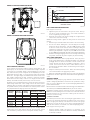
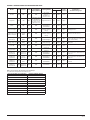
STEP 3. SENSITIVITY SELECTION
Set the sensitivity of the detector using the sensitivity switch (Figure 10) and
digital display. Use the chart below to determine which setting is acceptable
(per UL 268) for your installed distance. Before attempting to set the sensi-
tivity, make sure that you have completed the fine adjustment process (the
digital display should be “OFF”). To set the sensitivity, depress the sensitivity
button once. The digital display will illuminate and read the current sensi-
tivity setting as indicated on the chart. Continue to depress the sensitivity
button until the desired setting is achieved. The display will turn off auto-
matically. The default sensitivity will be factory set at level 4 or 50%.
In addition to the four standard sensitivity selections the detector has two Ac-
climate settings. When either of these settings is chosen the detector will au-
tomatically adjust its sensitivity using advanced software algorithms to select
the optimum sensitivity for the environment. The sensitivity will be continu-
ously adjusted within the ranges specified in the chart above.
Sensitivity
Setting
Percent
Obscuration
Display
Reading
Acceptable Distance
Between Detector & Reflector
Feet Meters
Level 1 25 25 16.4 to 120 5.0 to 36.6
Level 2 30 30 25 to 150 7.6 to 45.7
Level 3 40 40 60 to 220 18.3 to 67
Level 4 50 50 80 to 328 24.4 to 100
Acclimate
Level 1
30 to 50 A1 80 to 150 24.4 to 45.7
Acclimate
Level 2
40 to 50 A2 80 to 220 24.4 to 67
Total obscuration can be converted to percent per foot, assuming uniform
smoke density for the entire length of the beam. The chart below converts
total obscuration to percent per foot for all acceptable sensitivity settings.
2.0
1.5
1.0
0.5
0.0
0
25% SETTING
30% SETTING
40% SETTING
50% SETTING
50 100 150 200 250 300 350
OBSCURA
TION (%/FT.)
SENSITIVITY IN PERCENT PER FOOT VS. DISTANCE
(ASSUMES UNIFORM SMOKE DISTRIBUTION)
DISTANCE IN FEET
C0268-00
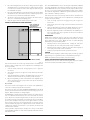
STEP 4. COMPLETING THE INSTALLATION
Refer to Figure 13 for this step.
1. Tighten the optics lock down screws so the optics are secure. Take spe-
cial care not to shift or disturb the optics. Use a hand screwdriver to
avoid over-tightening or jarring the optics.
2. Install the outer housing of the detector, making sure to tighten all four
screws in each corner of the housing.
NOTE: The housing contains a gasket seal that protects the detector from
moisture.
3. Remove the protective film from the front surface of the outer housing.
4. Press the reset button, making sure to avoid blocking the line-of-sight
between the detector and reflector. The yellow LED will begin to blink
for about 20 seconds. At this time, the detector is making its final gain
adjustment to compensate for the effects of installing the outer housing.
When the gain adjustment is complete, the yellow LED will turn off and
the green LED will begin blinking, indicating a successful gain adjustment.
5. Install the trim ring by snapping it onto the outer housing. If the trim ring
was painted, ensure that the paint is completely dry before installing.
STEP 5. FINAL VERIFICATION
1. Block the entire reflector with an opaque material. Nearly any non-re-
flective opaque material will do, including this manual or the cardboard
packaging inserts. The detector should enter a trouble condition, indi-
cated by the fault relay and the yellow LED (see Appendix 1) after 30
seconds. If the detector does not enter a trouble condition, there is a
problem with the installation. Refer to troubleshooting section in Appen-
dix 1 for assistance.
2. Complete a sensitivity test of the detector. Refer to the Sensitivity Testing
section of this manual for the appropriate procedure.
3. Remove the orange adhesive-backed sheet used to aid in coarse adjustment.
Congratulations. You have completed the final installation and alignment pro-
cedure.
SENSITIVITY TESTING
NOTE: Before testing, notify the proper authorities that the smoke detector
system is undergoing maintenance, and therefore the system will be tempo-
rarily out of service. Disable the zone or system undergoing maintenance to
prevent unwanted alarms.
Detectors must be tested after installation and following periodic maintenance.
The sensitivity of the BEAM1224/BEAM1224S may be tested as follows:
NOTE: Before testing the detector, check for the presence of the flashing green
LED at the receiver, making sure not to disturb or block the beam. If it does
not flash and the detector is not in trouble or alarm, power has been lost to
the detector (check the wiring).
A. Calibrated Test Filter
The sensitivity of the detector can be tested using an opaque material to cover
the reflector by an amount indicated by the graduated scale on the reflector.
(Due to the high optical efficiency of the reflector the selection of the opaque
material used to block the reflector is not critical. Acceptable materials in-
clude, but aren’t limited to, this manual or the cardboard packaging inserts.)
Refer to Figure 14 for this procedure.
1. Verify the sensitivity setting of the detector in % obscuration. See the
Sensitivity Selection section of this manual for sensitivity determination
if sensitivity is unknown.

8 I56-2294-007R
06-10
2. Place the blocking material over the reflector, lining it up with the gradu-
ated marks that are 10 less than the detector’s setting in percent obscura-
tion. The detector should not alarm or fault. Keep the material in place
for a minimum of 1 minute.
3. Place the blocking material over the reflector lining it up with the gradu-
ated marks that are 10 more than the detectors setting in percent obscu-
ration. The detector should enter alarm within 1 minute.
4. The detector can be reset with the reset switch on the detector unit, re-
mote reset, or momentarily interrupting power.
5. Notify the proper authorities that the system is back on line.
FIGURE 14. REFLECTOR TEST CARD PROCEDURE:
LINE UP EDGE OF
TEST CARD WITH
APPROPRIATE
OBSCURATION LEVEL
MOVE TEST CARD TO DESIRED AMOUNT OF OBSCURATION
C0267-00
If the detector fails this test several steps should be taken to determine if the
detector is faulty or simply needs to be re-adjusted before returning the unit.
These steps include:
1. Verify all wiring connections and appropriate power is applied to
the detector.
2. Verify that the optical line of sight is free from obstructions and reflec-
tive objects.
3. Apply the maintenance procedure in this manual. Repeat the test proce-
dure. If the detector still fails the test procedure proceed with step 4.
4. Repeat the alignment procedure in this manual. If the alignment proce-
dure is successful repeat the test procedure. If the detector still fails the
test it should be returned.
B. Test Switch
The detector can be tested using the local test switch on the transmitter/re-
ceiver unit or remotely using the remote test station.
The remote test can be used with the BEAM1224/BEAM1224S beam smoke
detector. Follow instructions included with the test station for proper use. See
Figure 8 (Remote Test Station) for wiring diagram.
The BEAM1224S is equipped with an integral sensitivity test feature that con-
sists of a calibrated test filter attached to a servo motor inside the detector
optics. When a test is initiated using the remote test station or local test switch
the test filter is moved in the pathway of the light beam. The on-board micro-
processor then determines if the proper level of signal reduction is received
at the receiver. If the proper level of signal reduction is received the detector
will enter alarm. If the proper level of signal reduction was not achieved, indi-
cating that the sensitivity of the detector is out of tolerance, the detector will
enter the trouble condition.
Always perform a complete reflector blockage test as in step 4 of the Instal-
lation/Alignment procedure to ensure that the pathway between the detector
and reflector is clear.
Note: For the BEAM1224 this test does not satisfy the requirements of NFPA72
for periodic maintenance and sensitivity verification of beam type detectors.
For the BEAM1224S this test in conjunction with the complete reflector block
-
age test (see step 4 of the Installation/Alignment procedure in this manual)
does satisfy the requirements of NFPA72 for periodic maintenance and sensi-
tivity verification of beam type detectors.
If the detector fails this test several steps should be taken to determine if the
detector is faulty or simply needs to be re-adjusted before returning the unit
for repair. These steps include:
1. Verify all wiring connections and appropriate power is applied to
the detector.
2. Verify that the optical line of sight is free from obstructions and reflec-
tive objects.
3. Apply the maintenance procedure in this manual. Repeat the test proce-
dure. If the detector still fails the test procedure proceed with step 4.
4. Repeat the alignment procedure in this manual. If the alignment proce-
dure is successful repeat the test procedure. If the detector still fails the
test it should be returned.
MAINTENANCE
NOTE: Before cleaning the detector, notify the proper authorities that the
smoke detector system is undergoing maintenance, and therefore the system
will be temporarily out of service. Disable the zone or system undergoing
maintenance to prevent unwanted alarms.
1. Carefully clean the outer housing lens face. A damp soft cloth with a
mild soap may be used. Avoid products with solvents or ammonia.
2. Carefully clean the reflector. A damp soft cloth with a mild soap may be
used. Avoid products with solvents or ammonia.
3. Notify the proper authorities that the system is back on line.
PAINTING
The outer aesthetic ring may be painted using a spray or brush type paint of
appropriate type. See specification section of this manual for paint types.
NOTE: Never paint the flat lens surface of the outer housing.
SPECIAL NOTE REGARDING SMOKE DETECTOR GUARDS
Smoke detectors are not to be used with detector guards unless the combina-
tion has been evaluated and found suitable for that purpose.

9 I56-2294-007R
06-10
APPENDIX I. OPERATION MODES AND TROUBLESHOOTING GUIDE:
Modes Red Yellow Green
Dual Digital
Display Readout
Initiating Means
Alarm Contacts
Fault
Contacts
Comments &
Troubleshooting Tips
Alarm Remote
Normal OFF OFF Blink OFF
Successful
completion of
initialization or
detector reset
Open OFF Close
Alignment OFF ON OFF
On, Relative amount
of signal 0-99, or
– if automatic gain
resetting, or Lo if
signal is too low
Alignment Switch Open OFF Open
Alarm ON OFF OFF OFF
Smoke, Test Filter,
RTS451/KEY or
RTS151/KEY
Close ON Close
Trouble-Drift Comp
Elevated Signal
OFF
3 Quick
Blinks
Blink OFF
Long Term Drift
Reference Out of
Range
Open OFF Open
• Sunlight into detector or reflector.
• Re-Align detector.
Trouble-Drift Comp
Reduced Signal
OFF
2 Quick
Blinks
Blink OFF
Long Term Drift
Reference Out of
Range
Open OFF Open Clean detector and reflector.
Trouble-Signal
Over Range
OFF
2 Quick
Blinks
Blink OFF
Increase of
Reflected Signal
Open OFF Open
Inspect line of sight between
detector and reflector for reflective
objects in the pathway.
Trouble-Beam
Blockage Response
OFF
4 Quick
Blinks
OFF OFF Beam Blockage Open OFF Open
• Remove blockage.
• Faulty unit.
Initialization-
Power On
OFF
Blink until
complete
Blink OFF
Apply Power from
discharged state.
Open OFF Close
Initialization-
Alignment Exit
OFF
Blink until
complete
Blink OFF
Depressing
RESET switch after
alignment
Open OFF Close
Local Test
(BEAM1224S)
Pass Result
ON
Blinking the
amount of
drift used.
OFF OFF
RTS451/KEY or
RTS151/KEY
Close ON Close
Detector remains in alarm until reset
or time-out
Local Test
(BEAM1224S)
Fail Result
OFF
On until
reset or
time-out
Blink OFF
RTS451/KEY or
RTS151/KEY
Open OFF Open
Detector remains in fault until reset
or time-out
Local Test
(BEAM1224)
Fail Result
OFF
Per fault
mode
Blink OFF
RTS451/KEY or
RTS151/KEY
Open OFF Open
If local test fails will already
be in fault
Local Test
(BEAM1224)
Pass Result
ON
Blinking the
amount of
drift used.
OFF OFF
RTS451/KEY or
RTS151/KEY
Close ON Close
Blinks output by Yellow LED and Remote Trouble Output
once the device has passed a local remote test:
Percent The Detector Has Drifted Number Of Blinks Output
<10% None
<20% 1
<30% 2
<40% 3
<50% 4
<60% 5
<70% 6
<80% 7
<90% 8
<100% 9

10 I56-2294-007R
06-10

11 I56-2294-007R
06-10
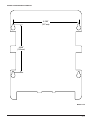
APPENDIX II. DETECTOR DRILLING TEMPLATE:
4.345˝
6.190˝
(157 mm)
(110 mm)
Scale = 1:1

12 I56-2294-007R
06-10

13 I56-2294-007R
06-10
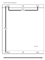
APPENDIX III. REFLECTOR DRILLING TEMPLATE:
Scale = 1:1
5.512˝
(140mm)
8.465˝
(215mm)

14 I56-2294-007R
©2016 System Sensor. 06-10
Please refer to insert for the Limitations of Fire Alarm Systems
System Sensor warrants its enclosed smoke detector to be free from defects in materials
and workmanship under normal use and service for a period of three years from date
of manufacture. System Sensor makes no other express warranty for this smoke detec
-
tor. No agent, representative, dealer, or employee of the Company has the authority to
increase or alter the obligations or limitations of this Warranty. The Company’s obligation
of this Warranty shall be limited to the repair or replacement of any part of the smoke
detector which is found to be defective in materials or workmanship under normal use
and service during the three year period commencing with the date of manufacture.
After phoning System Sensor’s toll free number 800-SENSOR2 (736-7672) for a Return
Authorization number, send defective units postage prepaid to: Honeywell, 12220 Rojas
Drive, Suite 700, El Paso TX 79936, USA. Please include a note describing the malfunc
-
tion and suspected cause of failure. The Company shall not be obligated to repair or
replace units which are found to be defective because of damage, unreasonable use,
modifications, or alterations occurring after the date of manufacture. In no case shall the
Company be liable for any consequential or incidental damages for breach of this or any
other Warranty, expressed or implied whatsoever, even if the loss or damage is caused by
the Company’s negligence or fault. Some states do not allow the exclusion or limitation of
incidental or consequential damages, so the above limitation or exclusion may not apply
to you. This Warranty gives you specific legal rights, and you may also have other rights
which vary from state to state.
THREE-YEAR LIMITED WARRANTY
FCC STATEMENT
This device complies with part 15 of the FCC Rules. Operation is subject to the following two conditions: (1) This device may not cause harmful interference, and (2) this device must
accept any interference received, including interference that may cause undesired operation.
NOTE: This equipment has been tested and found to comply with the limits for a Class B digital device, pursuant to Part 15 of the FCC Rules. These limits are designed to provide
reasonable protection against harmful interference in a residential installation. This equipment generates, uses and can radiate radio frequency energy and, if not installed and used
in accordance with the instructions, may cause harmful interference to radio communications. However, there is no guarantee that interference will not occur in a particular instal
-
lation. If this equipment does cause harmful interference to radio or television reception, which can be determined by turning the equipment off and on, the user is encouraged to
try to correct the interference by one or more of the following measures:
– Reorient or relocate the receiving antenna.
– Increase the separation between the equipment and receiver.
– Connect the equipment into an outlet on a circuit different from that to which the receiver is connected.
– Consult the dealer or an experienced radio/TV technician for help.
-
 1
1
-
 2
2
-
 3
3
-
 4
4
-
 5
5
-
 6
6
-
 7
7
-
 8
8
-
 9
9
-
 10
10
-
 11
11
-
 12
12
-
 13
13
-
 14
14


System Sensor BEAM1224 and BEAM1224S User manual
- Type
- User manual
Ask a question and I''ll find the answer in the document
Finding information in a document is now easier with AI
Related papers
-
System Sensor BEAMLRK User manual
-
-
-
-
-
-
-
-
-
Other documents
-
Notifier BEAM1224(A) and BEAM1224S(A) Conventional Beam Smoke Detectors Operating instructions
-
 Firesense SS-BEAM Installation guide
-
Notifier FSB-200S User manual
-
Potter F5000 User manual
-
ANZZI BA-LMDFX011AL User manual
-
-
-
EDWARDS EC-50R-100R Installation guide
-
-
Ampac Beam Detector Addressable Installation guide
