Page is loading ...

L
SEAIRS
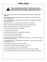
CAUTION:
Read Rules for
Safe Operation
and Instructions
Carefully
32" CRAFTSMAN LAWNSWEEPER
® Assembly
Operation
® Maintenance
® Repair Parts
Sears, Roebuck and Co, Chicago, Ill 60684 USA
PRINTED IN U S A

RULES FOR SAFE OPERATION
The following safety precautions are suggested This
lawn sweeper is designed, engineered and tested to
offer reasonably safe and effective service,
provided it is operated in strict accordance with these
instructions Failure to do so may result in personal
injury. Always observe the rules for safe operation..
1. Do not allow anyone to operate the sweeper
without proper instructions°
2. Do not permit children to operate sweeper.
3. Do not push or tow sweeper too close to a fire,
because the hopper and brush will burn,
4, Do not attempt to remove wire or string
wrapped around brush while brush is rotating,
5. Operate sweeper at reduced speed on rough
terrain, in ditches, and on hillsides to prevent
tipping and toss of control Stay alert for holes
or other hidden hazards..
6. This sweeper is not meant for street or highway
use.. Watch for traffic when sweeping near
roadways,
7. Keep all nuts, bolts and screws tight to be sure
equipment is in safe working condition.
8 Vehicle and attachments should be stopped and
inspected for damage after striking a foreign
object and damage should be repaired before
restarting and operating the equipment
9 Follow maintenance instructions as outlined in
this manual.,
Your lawnsweeper carton and inner pack parts
carton contains parts as shown in the figure below.
The hardware package contains two separate
packages, see figures 1 and 2 on page 3. Identify
all parts and layout as shown in the figure below and
figures 1 and 2.
8, Lower Hopper Tube, Left Hand
9, Hopper Bag
10 Wind Screen
CARTON CONTENTS
Loose Parts in Carton
t,
2.
3.
4,
5°
6,
7,
Sweeper Housing Assembly
Brace Rod
Bag Retainer Strap
Bag Frame Strap
Upper Hopper Tube, Right Hand
Upper Hopper Tube, Left Hand
Lower Hopper Tube, Right Hand
LOOSE PARTS IN CARTON
PARTS IN INNER PACK CARTON:
!1, Bag Support Rods (2) 3/16" Dia,
12. Height Adjustment Strap
13. Hitch Bar
14, Hitch Bracket
15 Hopper Mount Arms (2)
16. Rope
17 Hardware Package (Not Shown)
5
11
16
13
t5
2

CONTENTS OF HARDWARE PACKAGE: (Figure tL
Sweeper Housing AssembLy
A (I)
B (2)
C (1)
D (2)
E (2)
F (2)
G (8)
H (t)
t (1)
J (2)
K (3)
L (2)
M (t)
N (1)
0 (1)
P (1)
R (1)
Hitch Pin
Spacers 1" Dia, x 3/4" Long
Hairpin Cotter
Hex Bolts 3/8"16 x 3/4" Long
Hex Bolts 3/8q6 x 1-1/4" Long
Flat Washers 3/8" I,D
Hex Lock Nuts 3/8-16 Thread
Hex Bolts 3/8-16 x 1-1/2" Long
Flat Washer 17/32" x t-t/2 x t0 Ga
Flat Washer 5/16" I,D,
Hex Bolts 3/8-16 x t" Long
Carriage Bolt 5/16-18 x 3/4" Long
Spacer 13/32 I.D x 5/8" OD, x 3/16" Thk
Loci< Washer 5/16" I D
Hex Nut 5/16-t8 Thread
Hand Knob
Grip
_<_£_-_-y @ @-_--W _l_r _-'Ac
CONTENTS OF HARDWARE PACKAGE: (Figure 2L
Hopper Bag Assembly
S (4) Hopper Mounting Clamps
T (4) Hex Bolts 5/16-18 x 3/4" Long
U {4) Hex Loci{ Nuts 5/16-t8 Thread
V (2) Hex Bolts I/4-20 x H/4" Long
W (4) Hex Lock Nuts 1/4-20 Thread
X (4) Truss (Slotted) Head Screws #10-32 x
5/8" Long
Y (4) Hex Lock Nuts #10-32 Thread
Z (2) Clevis Pins 3/8" x 3" Long
AA (2) Curved Head Bolts 1/4-20 x 1" Long
AB (2) Hex Bolts 3/8-16 x 3/4" Long
AC (2) Hex Lock Nuts 3/8-16 Thread
AE (2) Bag Retainer Clevises
AF (2) Cotter Pins 1/8" x 3/4" Long
:tGURE 2
3/8- x 1-1/2-
318'" LOCK
lU.llUl, iii
[ F
318- x 1'"
3!8- x 1-114"
1/4- LOCI{
5/16" STD
3/8" STD t7/32"' x t_1/2"'
.......... i, .,, , H,,, ,,,,i,,i,H,,u , i,u
:ULL SIZE HARDWARE REFERENCE CHART
I #10 x5_8 "'
_ -
#10-32 HEX' 1/4" × 1
LOCI{ NUT
i ,,,, ,.
5/16"" × 314-
CARRIAGE
©
5116" LOCK
CURVED
r _
_r
i
/
/
5!16'" x 3/4-
5/16"
5116" LOCI{

ASSEMBLY 0NSTRUCTIONS
TOOLS REQUIRED
(1) Adjustable Wrench
(I) 3/8" Open End or Box Wrench
(1) 7/16" Open End or Box Wrench
(1) 1/2" Open End or Box Wrench
(1) 9/t6" Open End or Box Wrench
(1) Standard Screwdriver
(t) Pair of Pliers
Refer to carton contents figure on page 2 and figure
I on page 3 for parts and hardware needed to
assemble sweeper housing,,
Assemble the hitch bar to the sweeper housing,
place hitch bar under sweeper housing as
shown in figure 3, then secure hitch bar with
two 3/8" x 1" hex bolts and 3/8" lock nuts. See
figure 3. Do not tighten at this time.
TOP VIEW
3/8" x 1" HEX BOLT
(FRONT HOLE)
HITCH BRACKET
POSITION SEE
GROUP "B" PAGE 10,
HITCH BAR
3t8'" HEX LOC!( NUT
HITCH BRACKET POSITION
SEE GROUP "A'" PAGE 10.
FIGURE 4
BOTTOM VIEW
FIGURE 3
3/8" x 1" HEX BOLTS
HITCH BAR " '
SWEEPER HOUSING
_,_,
_NOTE
Before assembling the hitch bracket
to the hitch bar refer to figure 4 and
page 10 to determine which position
is required for your Sears riding
mower or tractor.
2o Assemble the hitch bracket to hitch bar with one
3/8" x 1" hex bolt (in the front hole) and 3/8"
hex lock nut,, Do not tighten at this time_ See
figures 4 and 5o
3 AssembJe the hitch bracket with one 3/8" x
1-1/2" hex bolt (in the back hole), large flat
washer and 3/8" hex lock nut, (Do not tighten
at this time), See figures 4 and 5,
3/8" x I-1/2" HEX
LARGE FLAT WASHER
3/8" HEX LOCK
BRACE
SWEEPER HOUSING
BACK HOLE IN
HITCH BRACKET
BAR
4
FIGURE 5
_NOTE
Cut the plastic tie down holding
height adjustment lever and move
lever down,
4 Assemble the two bag mount arms and top
ends of brace rod. See figure 6. Assemble the
top hole in arms to sweeper housing using two
3/8" x 3/4" hex bolts and 3/8" lock nuts, The
notched side of mount arms face upward and
mount on the inside of housing. See figure 6o
Assemble the brace rod under hitch bar and
large flat washer in back hole of hitch bracket
and brace rod ends to bottom holes in arms and
sweeper housing, using two 3/8" x 1-1/4" hex
bolts, 3/8" flat washers and 3/8" hex loci< nuts.
See figures 5 and 6,
5 Now tighten hex bolts assemb(ed in step 1,then
all others assembled in steps 2, 3 and 4

BAG MOUNT
\
318'" x 314"
HEX BOLT
x 1-1t4"
HEX
BOLT
BRACE
ROD
END
FIGURE 6
,, Assemble the height adjustment strap (hole end)
to the sweeper housing. See figure 7 Place
5/16" x 3/4" carriage bolt through the square
hole in right hand side of sweeper housing. Next
peace spacer into large hole on strap and over
end of carriage bolt, Secure with 5/16" flat
washer, 5/t6" !ock washer and 5/16" hex nut
See figure 7
HEIGHT ADJUSTMENT STRAP
_RIP
5116" x 3t4" CARRIAGE BOLT
SPACER HAND KNOB
5/16" FLAT WASHER 5116" FLAT WASHER
5/16" LOCI( WASHER 5/16" x 3/4" CARRIAGE
5f16" HEX NUT BOLT
,
,
,
Assemble other end of height adjustment strap
to height adjustment handle See figure 7. Place
slot on strap in line with square hole in height
ad}ustment handle Secure strap with 5/16" x
3/4" carriage bolt, 5/16" flat washer and hand
knob See figure 7. NOTE: Lightly coat slot with
grease for ease of adjustment.
Assemble the grip, with finger knobs as shown,
to the height adjustment handle, See figure 7,
Assemble the hitch pin, two 1" Diao x 3/4" long
spacers and hairpin cotter to the hitch bracket
and hitch bar. See figure 8 See page 10 for
adjustment before connecting lawnsweeper to
your Sears riding mower or tractor.
HITCH PIN
1" DIA.LoNGX3/4 ''_ ///HITCH BRACKET
' ) ,g
AR
HAIRPIN_COTTEI. _-"_."_-...
FIGURE 8
FIGURE 7

ASSEMBLY OF HOPPER BAG
Refer to carton contents figure on page 2 and figure
2 on page 3 for hardware needed to assemble
hopper bag. See page 2 to identify both upper and
lower hopper tubes.
Insert the left hand upper hopper tube through
the hopper bag stitched flaps, starting at the
center cut out in the top of the hopper bag, See
figures 9, 10 and I) Repeat for the right hand
upper hopper tube.
CENTER CUT OUT
START HERE
UPPER HOPPER TUBE
(LEFT HAND SHOWN)
/ /
BAG FLAP
FIGURE 9
Locate the hole on side of both upper hopper
tubes. See figure '10 The bag wilt require
piercing at these holes in a later step, Refer to
step 12 on page 8,
HOLE ON SIDE OF BOTH
UPPER HOPPER TUBES
COVERED BY BAG FLAP
FIGURE 10
__//
FIGURE 11
Slide the two upper hopper tubes together,
as shown in figure 11. Line up the center holes,
UPPER HOPPER TUBES
4o Secure the upper hopper tubes with 1/4" x 1"
curved head bolt and 1/4" hex loci< nut. See
figure 12o
1/4" HEX LOCI( NUT /
(INSIDE)
/
"_" x 1" CURVED HEAD BOLT
(OUTSIDE)
FIGURE 12
,,
Assemble the two lower hopper tubes as shown
in figure t3,, Secure with 1/4" x 1" curved head
bolt and 1/4" hex lock nut° See figure 13
1f4" x 1"
CURVED HEAD BOLT
FIGURE 13

6_
7_
Place assembled lower hopper tubes into
bottom of hopper bag, See figure !4.
Assemble the upper and lower hopper tube
ends together with two 318" x 3/4" hex bolts
(inside} and 3t8" hex lock nuts (outside), See
figure 14. Do not overtighten to allow for pivot,
UPPER HOPPER TUBE
3/8" HEX LOCK NUT
(OUTSIDE)
HOPPER
"- TUBE
84 Assemble the bag frame strap (bottom) and bag
retainer (top) to the front edge of bag bottom_
Place the bag retainer on top and frame strap
on bottom. Secure with four #10 x 5/8" slotted
screws and #t0-32 hex lock nuts., See figure 15.
10, Secure the bag corners over lower hopper tube
by snapping the flap to bag bottom on each side,
See figure t7.
;NAPS
FLAP
FIGURE 17
Assemble the two hopper support rods as
shown in figures 18 and 19, Place top end of rod
into hole in upper tube and bend rod outwards
and snap bottom end of rod into hole in bottom
tube, NOTE: Rods are spring steel and require
bending or bowing as shown° Do not over bend
and lose bag support tension.
PRONT EDGE OF BAG
#10 x 518" SCREW
BOTTOM
'IsTRA p
_;_#10-32 HEX
LOCK NUT
FIGURE 15
9 Assemble the frame strap to the lower hopper
frame Secure with 1/4" x 1q/4" hex bolts and
1/4" lock nuts. See figure 16.
LOWER HOPPER FRAME
1t4"
(INSIDE)
FIGURE 16
114" × 1-tt4" HEX BOLT
(0 UTSIDE)
FRAME STRAP
7
IPPORT ROD
FIGURE 18
FIGURE 19
SUPPORT RODS

12o Locate hole along side of upper hopper tubes
and pierce a hole through the bag aligned with
the hole in the tube, See figure 20.
UPPER HOPPER TUBE
FIGURE 20
CLEVIS
BAG RETAINER
FIGURE 22
16 Secure
PIN
/
the rope to the top center of
hopper bag frame as shown in figures 23 and
24_
13.
Assemble mount clamps to each side of upper
hopper tube. Place one clevis pin through
clamps, hopper bag and hopper tube, then
secure clamps together with two 5/16" x 3/4"
hex bolts and 5/16" lock nuts,, See figure 21,
Tighten securely,
UPPER HOPPER TUBE
MOUNT
5/16" HEX LOCK NUT
5116" x 3/4" HEX BOI
CLEVIS PiN
FIGURE 23
FIGURE 21
14. Repeat step t3 for other side,
15. Assemble the bag retainers to clevis pins°
Secure with cotter pins, See figure 22.
NOTE
Bag retainers must pivot freely.
8
FIGURE 24

17.Assemblethewindscreento upperhoppertube,
Pullthefourcornerloopsandsnap,Seefigures
25 and26,
19. To removethe hopper bag frame from the
sweeper,simplyflip the bagretainersupward
and removethe bag°Seefigure 27.
UPPER
HOPPER
TUBE
OOP
SNAP
FIGURE 25
BAG
RETAINER
HOPPER MOUNT ARM
FIGURE 27
18.
To assemble the hopper bag frame to the
sweeper, simply hook the clevis pins into the
notches in mount arms, Bag retainers must pivot
freely to lock in position., See figure 26.
WIND SCREEN
FIGURE 26
9

A IMPORTANT
TO ASSURE BEST PERFORMANCE OF YOUR NEW
SWEEPER, THE FOLLOWING INSTRUCTIONS MUST
BE READ CAREFULLY. SEE FIGURE 28. YOU MUST
SET UP SWEEPER TO THE TOWING VEHICLE, SO
BOTTOM OF BAG FRAME IS APPROXIMATELY
LEVEL ON FLAT SURFACE, SUCH AS DRIVE OR
WALK. THIS SHOULD KEEP BAG OFF THE GROUND
APPROXIMATELY 3" TO 4"
LAWN TRACTORS IN TODAYS MARKET VARY IN
HEIGHT FROM GROUND TO HITCH APPROXIMATE-
LY 8" TO 13" TO OBTAIN THE CORRECT SWEEPER
BAG LEVEL , SEE FIGURE 28. THERE ARE EIGHT
DIFFERENT SPACER POSITIONS AVAILABLE. SEE
GROUPS A AND B..
GROUP "A" - For riding mowers
with 8" to 10-1/2" ground
cBearance to hitch.
HITCH BAR
\
t WITH HITCH BRACKET MOUNTED
I BELOW HITCH BAR
BLACK LINE IS TRACTOR HITCH
TWO SPACERS ABOVE TRACTOR
HTCr_Hrm ::.
ONE SPACER ABOVE AND BELOW
TRACTOR HITCH
, _ .................. [NOTE"USETH_S
_ ISPACER POSITION FOR
TWO SPACERS BELOW TRACTOR
HITCH
1
TWO SPACERS AND HITCH BAR
BELOW TRACTOR HITCH
rT3-f
! ,','4
t0
BRUSH HEIGHT ADJUSTMENT
APPROXIMATELY CENTERED
LEVEL
SURFACE _
APPROXIMATELY LEVEL
(3" to 4" FROM SURFACE)
:IGURE 28
GROUP "B" - For tractors
with 10.-1/2'" to 13" ground
clearance to hitch.
WITH HITCH BRACKET MOUNTED
ABOVE HITCH BAR
\ i t
CH BAR
BLACK LINE IS TRACTOR HITCH
I _ TWO SPACERS ABOVE TRACTOR
,-. HITCH __ __
NOTE: USE THIS SPACER
........................ ::-'_- POSITION FOR SEARS
qSJ %u TRACTORS
_-_ ONE SPACER ABOVE AND BELOW
TRACTORHITCH
f ..--
_'_ TWO SPACERS BELOW TRACTOR
HITCH
TWO SPACERS AND HITCH BRACKET
BELOW TRACTOR HITCH

OPERATION
Your sweeper is a precision piece of equipment.
Engineering skill and experience have been
combined to provide reasonable safety and
efficiency. However, as with any type of mechanical
equipment, carelessness or error on the part of the
operator can result in damage to your equipment.
Therefore, exercise care at all times and do not sub-
ject your sweeper to misuse.
SWEEPING SPEED
Try sweeping at different speeds to find the one most
suited to your conditions for maximum hopper bag
fill.
BRUSH HEIGHT ADJUSTMENT
To adjust your sweeper brushes to the best operating
height, loosen the adjustment knob and push down
on height adjustment lever to raise the brush. See
figure 29_ Best adjustment is when brush setting is
1/2" down into grass.. Always mow the grass to an
even height before sweeping.
B_
Do Not drive or dump the
sweeper too close to a fire as the
brushes and bag can be
destroyed by excessive heat or
flame.
TO LOWER BRUSH
(Pull Back)
ADJUSTMENT
ASS'Y
TO RAISE BRUSI-
iPush Down)
FIGURE 29
DUMPING OF SWEEPER
"(our sweeper can be dumped easily without getting
off of the rider or tractor_ Simply put) rope forward
to dump° See figure 30. SEE CAUTION NOTE A AND
B,
Always dump hopper after each use.. Damp or wet. ....
grass and leaves will cause damage to hopper if
stored for long period of time.
FIGURE 30
STORAGE
The bag may be collapsed for storage Remove the
two support rods and fold bag down
LUBROCATION/MAINTENANCE
The bearings in the sweeper have been prelubricated
at the factory; however, it is recommended that a
few drops of light oil should be added to the brush
shaft bearings twice a year. Also, the wheels should
be removed to clean gears every two years_ After
cleaning apply an even coat of light grease° See
figures 31, 32 and 33,
\
GEAR AND SHAI
®
FIGURE 3t
A_
_CAUTION
Do Not fasten rope to pulling
vehicle where it might become
entangled with driving wheels or
rotating parts.
_NOTE
To remove the wheel just pop off hub
cap with a screwdriver and remove
cotte_ pin and fiat washer. See figure
31o
tl

WHEEL GEARS/PAWL SERVICE
1, To service wheel gears, Do Not Remove both
wheels at the same time. Remove one wheel
at a time to prevent use of left hand parts on
right hand side, When removing gears make
notes on position of all washers and snap rings,
2, The paw!, inside ratchet gear, has a curved end
(side) and a flat end (side), See figure 32_ When
re-assembling ratchet gear and pawl, fill the
inside with grease. Re-assemble the wheel and
turn wheel, if the brushes drive (rotate) in both
directions, the pawi is assembled incorrectly,
remove and flip pawl over, If the brushes drive
(rotate) in one direction the pawl is assembled
correctly.
BRUSH
1.
2.
REPLACEMENT
Remove the hopper bag from lawnsweeper
Brush replacement should be done one
brush at a time,
3, Tip the sweeper back on housing for ease of
brush replacement° Do not remove hex bolts
from double brush retainers through brush
shaft.
4., Loosen hex bolts and hex lock nuts from single
brush retainers, See figure 33. Slide brush out
of retainers making note of over-lap bristles
position.
5 Install new brush, maldng sure over-lap bristles
are positioned the same as before and as shown
in figure 33 (end view of brush),
RATCHET
GEAR
PAWL
FIGURE 32
BRUSH
RIGHT END VIEW
ROTATION
OF BRUSH -------_.__.!
DOUBLE
BRUSH
RETAINER
OIL BEARING HERE
OVERLAP _
BRISTLES
OVER-LAP
BRISTLES
SINGLE
BRUSH
RETAINER
_'_BRUSH
SHAFT
SINGLE
BRUSH
RETAINER
BRUSH
ROTATION
FIGURE 33
12

NOTES
13

REPAaR PARTS FOR MODEL 488.240320 32" LAWN SWEEPER
18
67
67
69
!
23 40
/
27
5
36
2O
46
14
J/61516_
\ _,,/. 87
14

PART
NQ
1 43903
2 43886
3 43885
4 43645
5 43720
6 23387
7 43979
8 43928
9 43927
10 43930
11 43929
12 43956
t3 C-9M5732
14 43655
15 1650-21
16 44007
17 43182
!8 43407
19 44008
20 44137
21 43081
22 0142-000
23 43064
24 43661
25 43013
26 1095
27 43081
28 43064
29 43080
30 23400
31 43957
32 1652-13
33 1629-56
34 62445
35 43900
36 43012
37 62501
38 62489
39 23569
40 23580
41 23581
42 43901 .
43 23345
* Common hardware
REPAIR PARTS LIST FOR MODEL 486°240320 32" LAWNSWEEPER
QTY
4
1
1
I
1
1
1
1
1
1
1
t
8
2
4
4
4
2
2
4
2
2
2
4
12
4
2
I
1
I
1
2
2
1
2
8
1
2
1
4
8
2
2
DESCRIPTION
Brush
Pinion Gear-- R,,H
(Not Shown)
Pinion Gear- L.H
Skirt
Height Adjustment Knob
Height Adjustment Strap
Brace Rod
Upper Hopper Tube-RH
Upper Hopper Tube-LH
Lower Hopper Tube-R.H.
Lower Hopper Tube-LH_
Hopper Bag
Rivet
Retaining Ring-3/4"
Retaining Ring .594 loD,
FL-Washer (Shim) .596 x
1.125 x .025
Hex Bolt 5/16-18 x 3/4"
Lg.*
Hex Bolt 3/8-16 x 3/4" Lg.
(Gr. 5)
FL-Washer .783 x 1.125 x
.025
Flo-Washer ,,51 x ,990 x
_020
Washer 5/16" Stdo*
Cotter Pin I/8" Dia. x 3/4"
Lg.*
Hex Lock Nut 5/16-18 Thdo
Hex Boil t/4-20 x 1" Lg.*
Hex Lock Nut 1/4-20
Thd
Truss. Slotted Hd, Scr.
#10-32 x t/2" Lg.
Washer, 5/16" Std.
Hex Nut 5/16-!8 Thd,
Carriage Bolt 5/16-18 x
Lg.*
Bushing Spacer
Wind Screen
Bail Bearing .5916" IoDo
Bearing Retainer
Sweeper Housing Ass'y.
Dust Cover
Hex Bolt 1/4-20 x 3/4" Lg.
IGr.5)
Height Adjustment Tube
Ass'y
Brush Bushing Ass'y.
Brust&r.Shaft
Brush Retainer (Double)
Brush Retainer (Single)
Wheel Ass'y. Comp.
Skirt Retainer
46
47
48
49
50
51
52
53
55
56
57
58
59
60
61
62
63
64
65
66
67
68
69
7O
7t
72
73
75
76
77
78
79
8O
81
82
83
84
87
PART NO,
43943
43080
2674-32
23014
23330
23351
43926
1671-1
43346
43662
43064
43182
43013
43513
43407
43082
1509-90
0142-000
43978
2333'1
23349
23354
43001
43062
43082
R19172410
43082
43O70
43087
43343
23353
23368
43737
43064
19111116
62494
62495
43182
43086
44006
43920
DESCRIPTION
Grip
Carriage Bolt 5/16-18 x
3/4" Lgo*
Hub Cap
Hitch Bracket
Bag Mount Arn,
Bag Frame L trap
Wire Support
Pawl (HT,)
Truss Hd. Slotted Scr.
#10-32 x 5/8" Lg.
Hex Lock Nut #10-32 Thdo
Hex Lock Nut 5/16-t8
Thd.
Hex Bolt 5/16-!8 x 3/4"
Lg.*
Hex Loci< Nut t/4-20 Thdo
Clevis Pin 3/8" Dia. x 3"
Lg,
Hex Bolt 3/8-16 x 3/4"
Lg.*
Hex Lock Nut 3/8-16 Thd,
Hex Bolt 1/4-20 x t-I/4" Lg.*
Cotter Pin t/8" Dia. x 3/4"
Cg,_
Curved Hd Bolt 1/4-20 x
1" Lg.
Hopper Mount Clamp
Hitch Bar
Bag Retainer Clevis
Hex Bolt 3/8-16 x t" Lg.
(Gr. 5)
Bolt 3/8-t6 x 1-1/2"
Lg,*
Loci< Nut 3/8q6 Thd.
FL-Washer 17/32 x tq/2"
Hex Lock Nut 3/8q6 Thd.
FL-Washer 318" Std.
Hex Bolt 3/8-16 x 1-1/4"
Lg.*
Hairpin Cotter 5/32
Hitch Pin
Hitch Adjustment Tubes
Hopper Rope
Hex Lock Nut 5/16-18 Thd.
Washer, Std. 5/16" S.AE.
Wheel Hanger Ass'y,,oRoH.
Wheel Hanger Ass'y.-L H
Hex Bolt 5116-t8 x 3t4"
Lg.*
Loci< Washer 5/16" LD.*
Washer, Fiat 596 x .859
x .025
Owner's Manual
may be purchased locally,
15

How to Order
Repair Parts
32'" CRAFTSMAN
LAWNSWEEPER
Always mention the Model Number when requesting service
or repair parts for your Lawnsweeper.
Atl parts listed herein may be ordered from any Sears Service
Center and most Sears stores,
WHEN ORDERING REPAIR PARTS, ALWAYS GIVE THE
FOLLOWING INFORMATION:
eTHE PART NUMBER
eTHE PART DESCRIPTION
eTHE MODEL NUMBER
eTHE NAME OF MERCHANDISE
If the parts you need are not stocked locally, your order will
be electronically transmitted to a Sears Repair Parts Distribu-
tion Center for handling..
L M TED ONE YEAR WARRANTY
ON CRAFTSMAN LAWNSWEEPER
For one year from date of purchase, when this Lawnsweeper is
maintained and lubricated according to the operating and maintenance
instructions in the owner's manual, Sears will repair free of charge any
defect in material or workmanship.
This warranty does not cover:
-- repairs necessary because of operator abuse or negligence,
including the failure to maintain the equipment according to
instructions contained in the owner,s manual; and
-- Lawnsweeper used for commercial or rental purposes.
WARRANTY SERVICE 1S AVAILABLE BY CONTACTING THE NEAREST
SEARS SERVICE CENTER/DEPARTMENT IN THE UNITED STATES,.
This warranty applies only while this product is in use in the United
States,
This warranty gives you specific legal rights, and you may also have other
rights which vary from state to state..
Sears, Roebuck and Co., Di698-731A, Sears Tower, Chicago, IL 60684
I
Sears, Roebuck and Co.., Chicago, Ill. {50684 US
/