Planet 10/100/1000Mbps Gigabit Ethernet Web-manageable Switch User manual
- Category
- Network switches
- Type
- User manual
This manual is also suitable for

10/100/1000Mbps
Gigabit Ethernet Web-manageable Switch
GSW-1402S
User’s Manual

Trademarks
Copyright PLANET Technology Corp. 2003.
Contents subject to revision without prior notice.
PLANET is a registered trademark of PLANET Technology Corp. All other trademarks belong
to their respective owners.
Disclaimer
PLANET Technology does not warrant that the hardware will work properly in all environments
and applications, and makes no warranty and representation, either implied or expressed, with
respect to the quality, performance, merchantability, or fitness for a particular purpose.
PLANET has made every effort to ensure that this User’s Manual is accurate; PLANET
disclaims liability for any inaccuracies or omissions that may have occurred.
Information in this User’s Manual is subject to change without notice and does not represent a
commitment on the part of PLANET. PLANET assumes no responsibility for any inaccuracies
that may be contained in this User’s Manual. PLANET makes no commitment to update or keep
current the information in this User’s Manual, and reserves the right to make improvements to
this User’s Manual and/or to the products described in this User’s Manual, at any time without
notice.
If you find information in this manual that is incorrect, misleading, or incomplete, we would
appreciate your comments and suggestions.
FCC Warning
This equipment has been tested and found to comply with the limits for a Class A digital device,
pursuant to Part 15 of the FCC Rules. These limits are designed to provide reasonable
protection against harmful interference when the equipment is operated in a commercial
environment. This equipment generates, uses, and can radiate radio frequency energy and, if
not installed and used in accordance with the Instruction manual, may cause harmful
interference to radio communications. Operation of this equipment in a residential area is likely
to cause harmful interference in which case the user will be required to correct the interference
at his own expense.
CE Mark Warning
This is a Class A product. In a domestic environment, this product may cause radio interference,
in which case the user may be required to take adequate measures.
Revision
PLANET Web-manageable Gigabit Ethernet Switch User's Manual
FOR MODELS: GSW-1402S
Part No.: EM-GSW14V1

TABLE OF CONTENTS
CHAPTER 1 INTRODUCTION..............................................................................1
1.1 CHECKLIST.........................................................................................................................1
1.2 ABOUT THE SWITCH............................................................................................................1
1.3 FEATURES..........................................................................................................................1
1.4 SPECIFICATIONS.................................................................................................................2
CHAPTER 2 HARDWARE DESCRIPTION...................................................3
2.1 FRONT PANEL.....................................................................................................................3
2.2 REAR PANEL ......................................................................................................................3
2.3 HARDWARE INSTALLATION...................................................................................................4
CHAPTER 3 CONSOLE MANAGEMENT......................................................5
3.1 CONNECT TO PC................................................................................................................5
3.2 MAIN MENU ........................................................................................................................5
3.3 SYSTEM MENU ...................................................................................................................6
3.4 MANAGEMENT SETUP MENU................................................................................................7
3.5 DEVICE CONTROL MENU.....................................................................................................8
3.6 USER AUTHENTICATION MENU...........................................................................................12
3.7 SYSTEM UTILITY MENU .....................................................................................................12
4. WEB MANAGEMENT..........................................................................................15
4.1 START A WEB BROWSER SESSION....................................................................................15
4.2 MAIN PAGE.......................................................................................................................15
4.3 SYSTEM PAGE..................................................................................................................17
4.4 PORT PAGE......................................................................................................................18
4.5 VLAN PAGE.....................................................................................................................19
4.6 PORT AGGREGATION PAGE...............................................................................................21
4.7 MIRROR PAGE..................................................................................................................21
5 SWITCH OPERATION..........................................................................................22
5.1 ADDRESS TABLE...............................................................................................................22
5.2 LEARNING.........................................................................................................................22
5.3 FORWARDING & FILTERING ...............................................................................................22
5.4 STORE-AND-FORWARD .....................................................................................................22
5.5 AUTO-NEGOTIATION..........................................................................................................22
6. TROUBLESHOOTING........................................................................................24

APPENDIX A..................................................................................................................25
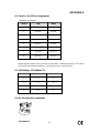
A.1 SWITCH‘S RJ-45 PIN ASSIGNMENTS..................................................................................25
A.2 10/100MBPS, 10/100BASE-TX........................................................................................25
A.3 RJ-45 CABLE PIN ASSIGNMENT..........................................................................................25

1
Chapter 1 INTRODUCTION
1.1 Checklist
Check the contents of your package for following parts:
l GSW-1402S.
l CD-ROM.
l Quick Installation Guide
l Power cord.
l 19” rack mount brackets.
l RS-232 cable.
If any of these pieces are missing or damaged, please contact your dealer immediately, if
possible, retain the carton including the original packing material, and use them against to
repack the product in case there is a need to return it to us for repair.
1.2 About the Switch
The Switch GSW-1402S is designed to allow simultaneous transmission of multiple
packets via an internal high-speed data channel. This means that it can partition a
network more efficiently than bridges or routers in most environments.
The Switch is equipped with Category 5 copper cable or fiber optic cable for uplinking to a
network backbone or network server. It is compatible with all 10Mbps, 100Mbps and
1000Mbps Ethernet environments. The increased speed and extra bandwidth offered by
Gigabit Ethernet will support faster and more users applications with generating more
traffic.
In addition, the Switch is also support two module slots for 10/100/1000Base-T,
1000Base-SX and 1000Base-LX modules to uplink to a server or network backbone.
These Switches are designed for Plug and Play installation, allows the network
administrator to simply connect the network and power cables and the Switching/bridging
functions begin automatically.
The front panels of these Switches provide LEDs for easy recognition of the switch
operation status and for troubleshooting. These LEDs display the power status for the
system and activity/ speed status for each port.
The built-in console interface and web interface can be used to configure the Switch’s
setting for VLAN, and Port Trunk Groups, Port Mirroring and Port Speed, flow control
enable/ disable.
1.3 Features
w 14 port 10/100/1000Base-T and 2 slots for 1000Base-T or 1000Base-SX/LX module
w 32Gbps switch fabric, true non-blocking switch architecture, wire-speed forwarding
w Provide 4K MAC address entries
w Complies with IEEE 802.3x, full-duplex flow control, IEEE 802.3z 1000Base-SX/LX,
IEEE 802.3ab 1000Base-T, IEEE 802.3/802.3u (10/100Base-TX), IEEE 802.1Q VLAN
w Configurable through console, Telnet and Web
w Support up to 255 802.1Q VLAN group
w Port Trunking Support
w Port Mirroring for dedicated ports monitoring
w MDI/MDI-X auto-detection

2
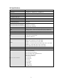
1.4 Specifications
Network Ports 14 x RJ-45, 10/100/1000Base-T
Module slot 2, 1000Base-T, 1000Base-SX, 1000Base-LX
Modes Half and Full Duplex, auto-negotiation
Console 1 x RS-232 DB-9
MAC address table size 4k
Switch Fabric 32Gbps
Transmission method Store-and-forward
Packet Buffer Memory 272K Bytes
Packet Forwarding Rate (64bytes)
14880pps @ 10Mbps
148800pps @ 100Mbps
1488000pps @ 1000Mbps
VLAN Support IEEE 802.1Q VLAN, up to 255 groups.
Trunk Trunking function can be set and prevent any loop and fail-over
Port mirroring Monitor sending packets of a specific port
MDI/MDI-X Auto MDI/ MDI-X on each port
LEDs
System: PWR, Status
Per port: ACT, 10, 100, 1000
Port Module: LNK, ACT
Cables
10Base-T: 2-pair UTP Cat. 3,4,5 up to 100m
100Base-TX: 2-pair UTP Cat.5, up to 100m
1000Base-T: 4-pair UTP Cat 5, up to 100m
1000Base-SX: 50/125 and 62.5/125 fiber-optic cable, up to 550m
1000Base-LX: 9/125 fiber optic cable, up to 10km
50/125 and 62.5/125 fiber-optic cable, up to 550m
Rack Mount 19” rack mount, 1U height
Management Interface Web, Console, and Telnet
Protocols and Standards
IEEE 802.3 (Ethernet)
IEEE 802.3u (Fast Ethernet)
IEEE 802.3z/802.3ab (Gigabit Ethernet)
IEEE 802.3x (flow control)
IEEE 802.1Q VLAN tag
RFC 768 UDP
RFC 783 TFTP
RFC 791 IP
RFC 792 ICMP
RFC 826 ARP
RFC 854 Telnet
RFC 2068 HTTP

3
Chapter 2 Hardware Description
This product series provide three different operating speed – 10Mbps, 100Mbps, and
1000Mbps in the same switch and automatically distinguish the speed of incoming
connection.
This section describes the hardware features of these Switches. For easier management
and control of the switch, familiarize yourself with its display indicators, and ports. Front
panel illustrations in this chapter display the unit LED indicators. Before connecting any
network device to the switch, read this chapter carefully.
There are three choices of different modules for expansion:
l 10/100/1000Base-T module
l 1000Base-SX module
l 1000Base-LX module
2.1 Front Panel
The unit front panel provides a simple interface monitoring the switching hub.
GSW-1402S Switch front panel
LED indicators
PWR Green On: power on
STATUS Green On: System is OK
Blink: Run Time Error occurs
ACT Green Blink: there is traffic transverses the port
10
100
LNK
1000
Green On: indicate link status and traffic s
peed (10
for 10Mbps, 100 for 100Mbps, 1000
for 1000Mbps)
Reset button
At the right side of front panel, the reset button is designed for reconfiguring the switch
without turn off and on the power.
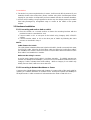
2.2 Rear Panel
The rear panel of the Switch indicates an AC inlet power socket, which accepts input
power from 100 to 240VAC, 50-60Hz, one RS-232 console port for setting up the switch
via a connection to a terminal or PC using a terminal emulation program, and two slide
slots for installing additional modules.
1516
CONSOLE
9600, 8, N, 1
100-240V AC
50-60Hz
GSW-1402S Switch front panel

4
Power Notice:
1. The device is a power-required device, it means, it will not work till it is powered. If your
networks should active all the time, please consider using UPS (Uninterrupted Power
Supply) for your device. It will prevent you from network data loss or network downtime.
2. In some area, installing a surge suppression device may also help to protect your switch
from being damaged by unregulated surge or current to the Switch or the power
adapter.
2.3 Hardware Installation
2.3.1 Connecting end node or hub or switch
1. Place the Switch on a smooth surface or fasten the mounting brackets with the
provided screws in a standard 19” rack.
2. Connect switch or PC to one port of the Switch using Category 3/4/5 UTP/STP
cabling.
3. Connect another switch or PC to the other port of Switch by following the same
process as described in Step 2.
Notice:
Cable distance for Switch
The cable distance between Ethernet Switch and hub/PC should not exceed 100 meter
for UTP/STP cable, 220m for 62.5/125 fiber cable and 550m for 50/125 fiber cable if
use 1000Base-SX module, 550m for 62.5/125 or 50/125 fiber cable and 10km for 9/125
fiber cable if use 1000Base-LX module.
Make sure the wiring is correct
It can be used Category 3/4/5 cable in 10 Mbps operation. To reliably operate your
network at 100Mbps and 1000Mbps, you must use an Unshielded Twisted-Pair (UTP)
Category 5 cable, or better Data Grade cabling. While a Category 3 or 4 cables may
initially seem to work, it will soon cause data loss.
2.3.2 Connecting to Network Backbone or Server
Connect to the Gigabit Ethernet ports with Category 5 copper cable or fiber optic cable for
uplinking to a network backbone or network server. These ports operate at 1000Mbps in
full-duplex mode. A valid connection is indicated when the 1000 or LNK LED is on.

5
Chapter 3 Console management
3.1 Connect To PC
RS-232 serial cable
Prepare a RS-232 serial cable. Attach the 9-pin female connector to the male connector
on the switch. Plug the other side of this cable to your PC.
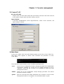
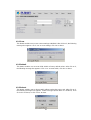
Hyper Terminal
In Windows 95/98/2000/XP, launch “HyperTerminal”, create a new connection, and
adjust settings as below:
3.2 Main Menu
Power on the switch; launch the new terminal program you just set up. Press “Enter” key,
then login screen appears as below. Enter username and password to access
GSW-1402S.
There are three system default accounts for different privilege levels:
“root”: root can do any configuration includes changing password and enable/disable
management capability via console port. The default password of root is
“superuser”. Note that this account is not workable on telnet and web
management interface.
“admin” admin can do any configuration except changing password. The default
password of admin is “admin”.
“guest”: guest can view the whole switch information only, moreover, access to Web
management interface is not allowed. The default password is “guest”.

6
Main menu appears after successfully login GSW-1402S. To enter any of the submenus,
simply type the number after the command prompt.
3.3 System Menu
System Menu contains two options: System Information and System Configuration.
3.3.1 System Information
This screen shows the hardware and software versions of current switch. Moreover,
information of System Contact, Device Name, and Device Location also included.
3.3.2 System Configuration
Select 2 from System Menu to configure System Contact, Device Name, and Device
Location.
System Contact: Who the System administrator is (optional)
Device Name: Naming the system (optional)
Device Location: Where the switch locates (optional)

3.4 Management Setup Menu
Management Setup Menu contains three options: Network Configuration, Console Port
Status Display, and Management Features Control.
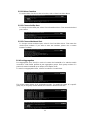
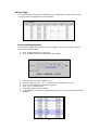
3.4.1 Network Configuration
To display the current network settings of switch, select 1 from Management Setup Menu.
This screen also allows user to modify these settings including IP address, Subnet Mask,
and Default Gateway.
Be reminded that after modifying some settings, you must use option 4 to apply changes,
and go back to Main Menu, use option 6 to save changes to NVRAM. Moreover, the IP
addresses of switch and Default Gateway have to be in the same IP segment; otherwise,
GSW-1402S will not apply such configuration.
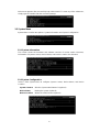
3.4.2 Console Port Status Display
To display the parameters used for console port access, select 2 from Management
Setup Menu.
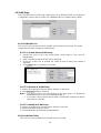
3.4.3 Management Features Control
This screen allows user to control web and telnet management features.
3.4.3.1 Web-based Capability
Select 1 from Management Features Control Menu. To enable or disable web
management interface, select 1. To view or modify HTTP access port number, select
2. Please note that GSW-1402S only accept port number 80 or range from 1000 to
2000.
7

8
3.4.3.2 Telnet Capability
Select 2 from Management Features Control Menu. To enable Telnet management
interface, select 1. To disable Telnet management interface, select 2.
3.5 Device Control Menu
Device Control Menu sets up the advanced functions of GSW-1402S include Port
Configuration, VLAN, Port Mirror, and Port Aggregation (Trunk).
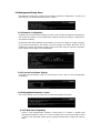
3.5.1 Port Status/Configuration
From Device Control Menu, select 1 to enter Port Status/Configuration Menu.
To display the status of each port, select 1 from Port Status/Configuration Menu. This
screen contains information of port number, connection type, Admin management, link
status, link speed, duplex, and flow control.
To modify port name, Admin status, link speed/duplex, and flow control, select 2 from Port
Status/Configuration Menu. Enter the port number you want to make change to, and set
the desired configurations.

9
3.5.2 IEEE802.1Q TAG VLAN
The VLAN is a group of ports that may spread around the network but communicate as
though they belong to one subnet. By using IEEE802.1Q compliant VLAN, all ports can be
reorganized into separate broadcast domains for security reasons and reduce bandwidth
occupation instead of using routers to divide whole network into subnets. It produces
cleaner network environment by reducing broadcast traffic and simplify network
management by allowing you to move devices to another VLAN without changing physical
connections.
Default settings of all ports are VLAN 1 and assigned PVID 1. Moreover, all ports of an
Aggregation Group must be treated as an integer when added to/deleted from a VLAN.
The IEEE802.1Q TAG VLAN Menu displays VLAN ID range, maximum number of
supported VLANs, the number of created VLANs, and active VLANs. Moreover, this menu
provides four options including VLAN Port Configuration, VLAN Table Status, VLAN Static
Entry Created, VLAN Static Entry Modification, and VLAN Static Entry Delete.
3.5.2.1 VLAN Port Configuration
To set the PVID of a specific port, select 1 from IEEE802.1Q TAG VLAN Menu. Enter
the port number you want to assign PVID to, and key in a desired number.
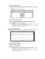
3.5.2.2 VLAN Table Status
To view the status of created VLANs, select 2 from IEEE802.1Q TAG VLAN Menu.
This screen shows VLAN ID, VLAN name, members of this VLAN, active status, and
creation time.

10
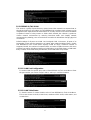
3.5.2.3 VLAN Static Entry Created
To create a static VLAN entry, select 3 from IEEE802.1Q TAG VLAN Menu. Enter the
information of VLAN ID, name, and active status.
3.5.2.4 VLAN Static Entry Modification
To modify an existing VLAN entry, select 4 from IEEE802.1Q TAG VLAN Menu.
Choose which VLAN you want to modify, then change the data in next screen.
3.5.2.5 VLAN Static Entry Delete
To delete an existing VLAN entry, select 5 from IEEE802.1Q TAG VLAN Menu.
Choose which VLAN you want to delete. After deletion, system will return to
IEEE802.1Q TAG VLAN Menu. You can use option 2 to check if the deletion is
successfully done or not.
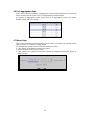
3.5.3 Mirror
Port mirror is used to mirror traffic from source port to a target port for analysis. Up to 2
ports can be monitored (mirrored) simultaneously by 1 sniffer port (target port). Please
note that the target port must be in the same VLAN as the source ports.
To enter Port Mirror Menu, select 3 from Device Control Menu. If Mirror Function is active,
the screen will show the current configurations.
If Mirror Function is Inactive, Port Mirror Menu would be shown as below.

11
3.5.3.1 Mirror Function
To set the Mirror Function active or inactive, select 1 from Port Mirror Menu.
3.5.3.2 Choose Sniffer Port
To change current sniffer port, select 2 from Port Mirror Menu. Then enter the desired
port number.
3.5.3.3 Choose Monitored Port
To change current monitored port, select 3 from Port Mirror Menu. Then enter the
desired port numbers. If you want to enter two numbers, please use a comma
between numbers.
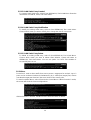
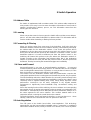
3.5.4 Port Aggregation
Port Aggregation (Port Trunk) is used to increase the bandwidth of a switch-to-switch
connection. GSW-1402S provides 8 port aggregation groups. Each group consists of 2
ports and creates bandwidth up to 4Gbps at full duplex mode.
To enter Port Aggregation Menu, select 4 from Device Control Menu.
This screen shows status of all aggregation groups. To modify the status of a specific
group, key in the group number below, then enable or disable its function.

12
However, before making trunk connections between switches, pay attention to:
1. The ports at both ends of a Port Aggregation connection must be configured as
Aggregation Ports.
2. The ports at both ends of a Port Aggregation connection must have the same port
properties, including Speed, Duplex mode.
3. All the ports of a Port Aggregation must be treated as an integer when added to/deleted
from a VLAN.
4. Before connecting cables between switches, enable the Pot Aggregation to avoid
looping.
5. Before disabling Port Aggregation, remove the connecting cables between switches to
avoid looping.
6. Both two slide-in slots should use the identical modules (two coppers / two fibers)
otherwise the Port Aggregation connection is invalid.
3.6 User Authentication Menu
User Authentication Menu shows the three sets of username and password of
GSW-1402S. To change the password, enter one available value after the command
prompt. Then assign a new password to it.
3.7 System Utility Menu
System Utility Menu provides some useful tools for GSW-1402S. To enter this menu,
select 5 from Main Menu.
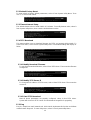
3.7.1 System Restart
This menu enables user to restart GSW-1402S without unplug the power cord. There are
two options: Cold Start, and Warm Start. Cold Start means switch will reboot with fully
Power On Self Test (POST). The system is completely checked but spends much time.
Warm Start reboots switch with less time spend.

13
3.7.2 Default Factory Reset
To reset switch to factory default parameters, select 2 from System Utility Menu. Then
click “Y” to reset GSW-1402S.
3.7.3 Timeout Interval Setup
The default timeout value of GSW-1402S is 5 minutes. To modify timeout value, select 3
from System Utility Menu, then enter the desired timeout value.
3.7.4 TFTP Download
This menu enables user to download firmware via TFTP and upgrade GSW-1402S. To
enter TFTP Menu, select 4 from System Utility Menu. The default settings will display as
follow.
3.7.4.1 Modify Download Filename
To specify the download filename, select 1 from TFTP Menu. Then enter the filename
of target file.
3.7.4.2 Modify TFTP Server IP
To change the IP address of TFTP server, select 2 from TFTP Menu. Then enter the
correct IP.
3.7.4.3 Start TFTP Download
After all above parameters are properly configured, select 3 from TFTP Menu.
System will connect to TFTP server and download the target file for upgrading.
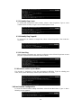
3.7.5 Ping
Ping is a simple but useful network tool. GSW-1402S implement this function to facilitate
network status diagnosis. To enter Ping Menu, select 5 from System Utility Menu.

14
3.7.5.1 Modify Ping Count
To modify the ping packet count number, select 1 from Ping Menu. Type a count
number from 1 to 1000, or type 0 for an infinite packet count.
3.7.5.2 Modify Ping Target IP
To change the IP address of target host, select 2 from Ping Menu. Then enter the
correct IP.
3.7.5.3 Start Ping
After all above parameters are properly configured, select 3 from Ping Menu to start
ping test. System will show the test result as follow.
3.7.6 Search Location by Port Name
This function is designed to ease the management difficulties. Type an existing port
name, then system will display matched port number(s) on screen.
3.8 Save Runtime Configuration
To save all current Runtime setting to NVRAM, select 6 from Main Menu. Type “Y” when
following screen appears.

15
4. Web management
4.1 Start A Web Browser Session
The Web Interface of GSW-1402S is coded by Java Applet and running on the JavaTM
Virtual Machine (JVM) version 1.3.1 platform. You should configure the management
station with an IP address and subnet mask compatible with GSW-1402S for accessing it.
Also, the management station should be well configured and connected to Internet for
automatically downloading (upgrading) the suitable JVM through Internet from
http://java.sun.com. Or you can download from
http://java.sun.com/j2se/1.3/download.html and manually install it.
Note: Usually the newer Java
TM
Virtual Machine is not backward compatible. JVM version
1.3.1 is strongly recommended to ensure properly operation.
The default network configurations are as follows:
IP: 192.168.0.1
Subnet Mask:255.255.255.0
Default Gateway: 192.168.0.254
Activate a web browser and enter “192.168.0.1” in the address field. A screen pops up and
asks for username/password. Use system default accounts admin/admin to access
GSW-1402S.
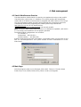
4.2 Main Page
Main Page appears after successfully login GSW-1402S. There are 7 function button
listed on top: Save, Default, Reboot, Ping, Telnet, Contact, and Upgrade.

4.2.1 Save
This button enables user to save current settings to NVRAM. After click on it, the following
message box appears. Click “Yes” to save settings, click “No” to abort.
4.2.2 Default
This button enables user to reset GSW-1402S to factory default values. After click on it,
the following message box appears. Click “Yes” to reset switch, click “No” to abort.
4.2.3 Reboot
This button enables user to reboot switch without unplug the power cord. After click on it,
the following message box appears. Select boot type (Warm Boot or Cold Boot). Then
click “OK” to reboot, or click “Close” to abort.
16
Page is loading ...
Page is loading ...
Page is loading ...
Page is loading ...
Page is loading ...
Page is loading ...
Page is loading ...
Page is loading ...
Page is loading ...
-
 1
1
-
 2
2
-
 3
3
-
 4
4
-
 5
5
-
 6
6
-
 7
7
-
 8
8
-
 9
9
-
 10
10
-
 11
11
-
 12
12
-
 13
13
-
 14
14
-
 15
15
-
 16
16
-
 17
17
-
 18
18
-
 19
19
-
 20
20
-
 21
21
-
 22
22
-
 23
23
-
 24
24
-
 25
25
-
 26
26
-
 27
27
-
 28
28
-
 29
29


Planet 10/100/1000Mbps Gigabit Ethernet Web-manageable Switch User manual
- Category
- Network switches
- Type
- User manual
- This manual is also suitable for
Ask a question and I''ll find the answer in the document
Finding information in a document is now easier with AI
Related papers
Other documents
-
 Eusso UGS5816-RW Owner's manual
-
 Eusso UGS5824-RW Owner's manual
-
Comelit IPSWC160A User manual
-
Airlink101 AGSW801 User manual
-
Edimax ES-5800D+ User manual
-
Xerox KS-801 User manual
-
Hawking HGS24S User manual
-
 Planet Technology GSD-1020 User manual
-
Repotec RP-G0401DC Owner's manual
-
 Eusso USH5005-XPA Owner's manual


