Page is loading ...

OmniView
™
KVM Switch with Micro-Cabling Technology
User Manual
ENTERPRISE Quad-Bus Series
F1DE108C
F1DE116C
F1DE208C
F1DE216C
Control up to 16 servers from up to two consoles
• Expandable to up to 256 from up to four consoles

TABLE OF CONTENTS
Introduction
Overview
Feature Overview . . . . . . . . . . . . . . . . . . . . . . . . . . . . . . . . . . . 2
Equipment Requirements . . . . . . . . . . . . . . . . . . . . . . . . . . . . . . 4
Operating Systems . . . . . . . . . . . . . . . . . . . . . . . . . . . . . . . . . . 4
Specifications . . . . . . . . . . . . . . . . . . . . . . . . . . . . . . . . . . . . . 5
Unit Display Diagrams . . . . . . . . . . . . . . . . . . . . . . . . . . . . . . . 6
Installation
Pre-Configuration . . . . . . . . . . . . . . . . . . . . . . . . . . . . . . . . . . 8
Standalone Switch Installation . . . . . . . . . . . . . . . . . . . . . . . . . .9
Connecting Multiple Switches (Daisy-Chaining) . . . . . . . . . . . . . . .13
DIP Switch Configuration Chart . . . . . . . . . . . . . . . . . . . . . . . . .14
Powering Up the Systems . . . . . . . . . . . . . . . . . . . . . . . . . . . . . 17
Using Your Switch
Selecting a Computer Using Direct-Access Port Selectors . . . . . . . . 18
Selecting a Computer Using Keyboard Hot Key Commands . . . . . . . . 20
AutoScan Mode . . . . . . . . . . . . . . . . . . . . . . . . . . . . . . . . . . . 21
Intelli
View
Graphical On-Screen Display Menu Control . . . . . . . . . . .22
The AutoUpdate™ Firmware Update Utility . . . . . . . . . . . . . . . . . .34
Troubleshooting . . . . . . . . . . . . . . . . . . . . . . . . . . . . . . . . . . . . .42
Glossary . . . . . . . . . . . . . . . . . . . . . . . . . . . . . . . . . . . . . . . . . . .44
Information . . . . . . . . . . . . . . . . . . . . . . . . . . . . . . . . . . . . . . . .46

INTRODUCTION
Congratulations on your purchase of this Belkin OmniView ENTERPRISE Quad-Bus
Series KVM Switch with Micro-Cabling Technology (the Switch). Our diverse line of
KVM solutions exemplifies the Belkin commitment to delivering high-quality, durable
products at a competitive price. Designed to give you control over multiple
computers and servers from up to four consoles, the Switch comes in a variety of
capacities suitable for all configurations, large or small.
Belkin has designed and developed this Switch with the server administrator in
mind. The result is the OmniView ENTERPRISE Quad-Bus Series KVM Switch, which
surpasses any other switch on the market. The Switch is engineered to work with the
most advanced server room and laboratory environments, offering:
• Dual-console* support, expandable to up to 4 consoles
• IntelliView Advanced Graphical On-Screen Display
• PS/2 and USB mix-and-match keyboard & mouse support
• Multilevel security feature
• USB flash-upgradeable
• Dedicated daisy-chain ports
• High video-resolution support (400MHz: up to 2048x1536@85Hz)
• Computer naming & group naming
• Server connection diagnostics
• Intuitive port indicators
• Direct-access port selectors
• Belkin 5-Year Warranty
• Dual-port, micro-construct KVM cables (sold separately)
*Available on 2x8 and 2x16 models only
This manual will provide details about your new Switch, from installation and
operation to troubleshooting–in the unlikely event of a problem. From time to time,
Belkin may release updates to this product; updated user information will be
available from our website belkin.com.
For quick and easy installation, please refer to the included Quick Installation Guide.
Thank you for purchasing the Belkin OmniView ENTERPRISE Quad-Bus Series KVM
Switch. We appreciate your business and have confidence that you will soon see for
yourself why over 1 million Belkin OmniView products are being used worldwide.
Package Contents:
• One OmniView ENTERPRISE Quad-Bus Series KVM Switch with Micro-Cabling
Technology
• Two Rack-Mount Brackets with Screws
• User Manual
• Quick Installation Guide
• IEC Power Supply Cable
• Registration Card
• One Set of Rubber Feet
1

2
OVERVIEW
Feature Overview
Quad-Bus Technology
Multiple Switches can be daisy-chained together to allow you to expand up to a
maximum of four consoles to simultaneously control up to 256 computers.
Integrated Dual-Console Support*
You can connect two consoles to simultaneously control up to 256 computers.
IntelliView Graphical On-Screen Display (OSD) with Mouse Support
The IntelliView OSD feature simplifies server management by allowing you to assign
individual names to each connected server throughout the system. You can also
create groups of computers, which you can use to organize your computers. The OSD
provides a visual means of switching between computers, checking computer
connection status; offers multilevel security; and sets the time interval for the
AutoScan function.
PS/2 & USB Mix-and-Match Keyboard
The Switch enables you to use either USB- or PS/2-type keyboards and mice to
control computers. Servers can be attached via either the computer’s USB or PS/2
interfaces by using the custom ENTERPRISE Quad-Bus Series KVM Dual-Port Cables.
AutoUpdate™
The exclusive AutoUpdate system from Belkin and flash-upgradeable firmware allows
you to obtain the latest firmware upgrades for your Switch. This allows you to
maintain consistent compatibility with the latest devices and computers. Firmware
updates are free for the life of your Switch. Please visit us at belkin.com for
complete update information and support.
Video Resolution
The Switch has 400MHz of video bandwidth, which supports video resolutions of up
to 2048x1536@85Hz.
Hot Keys
Hot key functionality allows you to select a desired port using designated key
commands. By using a simple hot key sequence on your keyboard, selecting one
computer from as many as 256 computers is instantaneous.
*Available on 2x8 and 2x16 models only

3
OVERVIEW
Reprogrammable Hot Key Initiator Sequence
The Switch allows you to select up to six alternate keys to initiate hot key
commands; this creates compatibility with keyboards that either do not feature
identical keys or that may have programmed the identical keys to perform other
functions. These settings can be configured through the IntelliView OSD. For more
information, please refer to the “IntelliView OSD Features” section of this manual on
pages 22 and 23.
AutoScan
The AutoScan feature allows you to set your Switch to scan and monitor the
activities of all connected computers, one by one. The time interval allotted for each
computer can be defined or adjusted through the On-Screen Display (OSD) menu.
Direct-Access Port Selectors
These buttons, conveniently located on the front face of the Switch, allow for
simple, manual port selection.
LED Display
An LED display on the front of the Switch serves as a status monitor. An LED above
each direct-access port selector lights to indicate which console currently controls
the corresponding computer. LEDs are color-coded to simplify the identification of
each console.
Seven-Segment LED Display
In standalone mode, the seven-segment LEDs indicate the port that has been
selected for each console. When daisy-chaining multiple Switches together, the
seven-segment LED display indicates the BANK number. During the computer
selection process, the seven-segment LEDs will briefly indicate the BANK that is
being selected; this allows the user to select any computer directly from the front
panel.
High-Density Computer Ports
The Switch features high-density, 50-pin, SCSI 2 connectors. These connectors allow
your ENTERPRISE Quad-Bus Series KVM Switch to fit into a 1U height
rack-mount case.
Micro-Cabling Technology
With a 60% reduction in size, this cabling technology offers easy cable management.
Supporting high video resolutions of up to 2048x1536@85Hz, these cables are
offered in both PS/2 and USB styles.

4
OVERVIEW
Equipment Requirements
Cables
To connect the Switch to a computer requires a specialized Belkin ENTERPRISE
Quad-Bus Series KVM Cable. For PS/2 computer connection, please use F1D9400-XX.
For USB computer connection, please use F1D9401-XX. To connect multiple BANKs
together, a specialized Belkin ENTERPRISE Quad-Bus Series Daisy-Chain KVM Cable
is required.
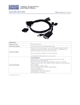
OmniView ENTERPRISE Quad-Bus Series Dual-Port KVM Cable
F1D9400-XX (PS/2 Style)
F1D9401-XX (USB Style)
OmniView ENTERPRISE Quad-Bus Series Daisy-Chain Cable
F1D9402-XX (Daisy-Chain)
(-XX denotes length in feet)
Operating Systems
The Switch is for use with computers running:
Platforms
• Windows® 98, 2000, Me, NT®, XP
• Red Hat® Linux® 7.0, 7.1, 7.2, Mandrake, Lindows
• Novell® NetWare® 5.x, 6.x
• Apple® Macintosh® products (Requires USB support, or the OmniView Mac
Adapter-F1D080)
Keyboards
• Supports most PS/2 and USB keyboards up to 101 keys
Mice
• Supports most PS/2 and USB mice
Monitor
• VGA
• SVGA
• MultiSync®
Note: DCC is not supported when monitors are connected to the ENTERPRISE Quad-Bus
Series KVM Switch.

5
OVERVIEW
Specifications
Part No.: F1DE108C, F1DE116C, F1DE208C, F1DE216C
Power: 100-240–264VAC @ 47–63Hz, single phase, 0.25A @ 117VAC,
0.15A @ 240VAC
Daisy-Chain: Maximum of 16 BANKs, including 4 consoles
Max. Number of PCs:
8 per BANK = 128 total (F1DE108C and F1DE208C),
16 per BANK = 256 total (F1DE116C and F1DE216C)
Keyboard Emulation: PS/2 & USB
Mouse Emulation: PS/2 & USB
Monitors Supported: VGA, SVGA, MultiSync, LCD monitors that accept analog input
Max. Video Resolution: 2048x1536@85Hz
Video Bandwidth: 400MHz
Max. Host Connections: 8 (F1DE108C and F1DE208C), 16 (F1DE116C and F1DE216C)
Keyboard Input: 6-pin miniDIN (PS/2), and USB Type A
Mouse Input: 6-pin miniDIN (PS/2), and USB Type A
Host Connectors: High-density, 50-pin, SCSI 2-style connector (Requires Belkin
ENTERPRISE Quad-Bus Series Dual-Port KVM Cable-F1D9400-XX or F1D9401-XX)
VGA Port: 15-pin HDDB type
Port LED Indicators: 8 (F1DE108C), 16 (F1DE116C and F1DE208C), 32 (F1DE216C)
Enclosure: Metal enclosure with high-impact plastic faceplate
Dimensions: 17 x 1.75 x 7.5 inch (431mm x 44.5mm x 190mm)
Weight:
(F1DE108C and F1DE208C) 9.2 lbs. (4173g)
(F1DE116C and F1DE216C) 9.5 lbs. (4309g)
Operating Temp: 32° to 104° F (0°~40° C)
Storage Temp: -4° to 140° F (-20°~60° C)
Humidity: 0-80% RH, non-condensing
Maximum Altitude: 10,000 ft.
Warranty: 5 years
Note: Specifications are subject to change without notice.

6
OVERVIEW
Unit Display Diagrams
Front View of the Switch (F1DE216C)
Dual manual
direct-access
port selectors
AutoScan button with
LED to indicate AutoScan
Mode is active
Manual BANK scroll
buttons
7-segment LED for selected
BANK address identification
(in daisy-chain mode)
Console LED to indicate
that this BANK is a
Primary console
LEDs for selected port
and console identification
Manual BANK
scroll buttons
Flip-down front fascia
Flash-upgrade port,
USB Type B
BANK selection
DIP switch
Reset button
Flip-down front fascia
Note: The 2x8 KVM Switch (F1DE208C) will look slightly different. It will include a
Shift LED to indicate that the Switch is in Shift mode (accessing Ports 9-16). The Shift
LED is located next to the 7-Segment LED.
Auto-Scan
Front View with Fascia Flipped Down (F1DE216C)

7
OVERVIEW
PS/2 mouse
console port
USB Console
ports, Type A
Video Console
ports VGA
4 high-density, 50-pin, SCSI 2-style
computer ports, each supporting 2 servers
(on the F1DE108C and F1DE208C)
8 high-density, 50-pin, SCSI 2-style
computer ports, each supporting 2 servers
(on the F1DE208C and F1DE216C)
IEC power connector
Daisy-chain
port, In
Daisy-chain
port, Out
Power switch
PS/2 keyboard
console port
Hosts 1 & 2 Hosts 3 & 4 Hosts 5 & 6 Hosts 7 & 8
Back View of the KVM Switch (F1DE208C)
Console 1 Console 2
(on F1DE208C
and F1DE216C)
Flash-upgrade port,
USB Type B
BANK selection
DIP switch
Reset button
Flip-down front fascia
Front View with Fascia Flipped Down (F1DE108C)

INSTALLATION
Pre-Configuration
The enclosure of the Switch is designed for desktop or rack-mount configuration. The
Switch is rack-mountable in standard 19-inch server racks. Rack-mount hardware is
included with these Switches for a sturdy rack installation. Anti-skid feet are
included for stable desktop configurations.
Consider the following when deciding where to place the Switch:
• Whether or not you intend to use the direct-access port selectors
• The lengths of the cables attached to your keyboard, monitor, and mouse
• The location of your computers in relation to your console
• The lengths of the cables you use to connect your computers to the Switch
• The placement of the daisy-chained BANKs in your server room, and the lengths
of the cables you use to connect the BANKs in your daisy-chain
Cable Length Recommendations
For PS/2 computers
We recommend that PS/2 cable length be limited to 25 feet for best video
performance. Beyond that length, the probability of video degradation increases.
For USB computers
We recommend that USB cable length be limited to 12 feet for best performance.
Installing the Switch into a Server Rack
The Switch includes mounting brackets ideal for installation in 19-inch racks.
Please consider the following before rack-mounting your Switch.
a) Elevated Operating Ambient Temperature – If installed in a closed or
multiunit rack assembly, the operating ambient temperature of the rack
environment may be greater than room ambient. Therefore, consideration
should be given to installing the equipment in an environment compatible
with manufacturer’s maximum rate ambient temperature.
b) Reduce Air Flow – Installation of the equipment in a rack should be such
that the amount of airflow required for safe operation of the equipment is not
compromised.
c) Mechanical Loading – Mounting of the equipment in the rack should be such
that hazardous condition is not achieved due to uneven mechanical loading.
d) Reliable Earthing – Reliable earthing of rack-mounted equipment should be
maintained. Particular attention should be given to supply connections other
than direct connections to the branch circuit.
8

9
INSTALLATION
1. Remove the brackets from the box.
2. Align the bracket with the front of the Switch for flush installation in your rack.
3. Attach the bracket to the side of your Switch with the screws provided.
4. Mount the Switch to the rack rail assembly.
*** Cautions and Warnings ***
Before attempting to connect anything to the Switch or your computer(s), please
ensure that all your computer equipment and devices are powered off. Belkin
Corporation is not responsible for damage caused by your failure to do so.
Standalone Switch Installation
This section provides complete instructions for the hardware setup of a single Switch.
Connecting Computers to the Switch (PS/2 Connection)
1. Attach the IEC power cable to the power connector located on the rear of the Switch.
Hosts 1 & 2 Hosts 3 & 4 Hosts 5 & 6 Hosts 7 & 8

10
INSTALLATION
2. Using the OmniView ENTERPRISE Quad-Bus Series Dual-Port PS/2 KVM Cable
(F1D9400-XX), connect the high-density, 50-pin, SCSI 2-style connector to a free
Switch port, starting with the port for the first two computers. (For best results,
screw the connectors into the Switch and the computer, when possible.)
3. Connect the VGA and PS/2 connectors to the computer (make sure that you connect
the keyboard and mouse cables to the correct ports on your computer; purple
indicates the keyboard connector and green indicates the mouse connector).
4. Repeat steps 1 through 3 for each additional computer you wish to connect.
Hosts 1 & 2 Hosts 3 & 4 Hosts 5 & 6 Hosts 7 & 8
Hosts 1 & 2 Hosts 3 & 4 Hosts 5 & 6 Hosts 7 & 8

11
INSTALLATION
Connecting Computers to the Switch (USB Connection)
1. Attach the IEC power cable to the power connector located on the rear of the Switch.
2. Using the OmniView ENTERPRISE Quad-Bus Series Dual-Port USB KVM Cable
(F1D9401-XX), connect the high-density, 50-pin, SCSI 2-style connector to a free
Switch port, starting with the port for the first two computers. (For best results,
screw the connectors into the Switch and the computer, when possible.)
3. Connect the USB connector of your KVM Cable to the computer. If your computer
is running Windows Me or newer, skip to step 6, otherwise continue with step 4.
Hosts 1 & 2 Hosts 3 & 4 Hosts 5 & 6 Hosts 7 & 8
Hosts 1 & 2 Hosts 3 & 4 Hosts 5 & 6 Hosts 7 & 8
Hosts 1 & 2 Hosts 3 & 4 Hosts 5 & 6 Hosts 7 & 8

12
INSTALLATION
4. Boot the computer you wish to connect via USB, as you would normally, with the
keyboard, mouse, and monitor connected directly to the computer.
5. Your computer will detect the Switch as a generic mouse and keyboard. Older
versions of Windows do not automatically install USB HID devices, so you will
have to manually press “Next” through the Windows Add/Remove Hardware Wizard
until the HID devices are all installed (the Switch will install four devices: a HID
keyboard, a HID mouse, a generic keyboard, and a generic mouse). This driver
installation is only required the first time the Switch enumerates on each
computer; the Switch will be detected and enumerate automatically in the future.
When driver installation is complete, power down the computer and disconnect
the keyboard, mouse, and monitor.
6. Connect the male VGA HDDB15 connector on the KVM Cable to the VGA port on
the computer.
7. Repeat steps 1 through 5 for each additional computer you wish to connect to
the Switch via USB.
Note: For USB Installation
We recommend you attach the KVM Cable directly to a free USB port on your computer,
not through a hub.
Connect the Console
1. Set BANK address (The BANK address is preset to zero at the factory).
2. Connect the monitor to the Switch. Attach your monitor cable to the HDDB15
female port on the back of the Switch labeled “Console”.
NOTE: Dual-console support available on 2x8 and 2x16 models only.
Hosts 1 & 2 Hosts 3 & 4 Hosts 5 & 6 Hosts 7 & 8

13
INSTALLATION
3. Connect the PS/2 or USB keyboard to the appropriate port on the back of the
Switch in the “Console” section (the purple PS/2 port).
4. Connect the PS/2 or USB mouse to the appropriate port on the back of the Switch
in the “Console” section (the green PS/2 port).
5. Repeat steps 1–4 above if you are connecting a second console.*
6. Power on the Switch.
7. Boot all of your host computers.
Connecting Multiple Switches (Daisy-Chaining)
You can daisy-chain up to 16 Switches and Expanders together; this will give a
server administrator control over a maximum of 256 computers. In addition, when a
second Switch is daisy-chained, two additional consoles can be added*, creating a
configuration of up to four consoles. Each daisy-chained group of Switches becomes
a unit that is referred to as a “BANK” and assigned an address. The Switch that the
console (keyboard, mouse, and monitor) is connected to is referred to as a “primary”
switch. BANKs 00 and 01 can be configured as primary console switches, allowing up
to four consoles. BANKs 02 through 15 can only be configured as secondary Switches
(without console support). If BANKs 00 through 01 do not have a console attached,
they function as secondary Switches. However, the connections on these BANKs are
hot swappable. For example, if a console is added to one of the first two BANKs, it
will immediately become a primary console Switch.
Note: A Daisy-Chain Cable (F1D9402-XX) is required to daisy-chain each OmniView KVM
Switch and is available through your Belkin reseller or online at http://www.belkin.com/
All OmniView ENTERPRISE Quad-Bus Series KVM Switches feature a “BANK DIP”
switch. The BANK DIP switch is used for proper identification of the Switch.
• For a single-unit configuration, set the BANK DIP switch on the Switch to the
“standalone” (BANK address 00) setting. This is the factory default setting.
• For multi-unit configuration, the BANK DIP switch on the primary units must be
set to BANK address 00 to (or) 01. Secondary units must be set to a unique
BANK address (from 02 through 15). Refer to the chart below for DIP switch
settings.
Note: BANK address 00 operates as standalone by default; refer to the section on the
OSD Options page for instructions on how to configure BANK 00 to join a daisy-chain.
*2x8 and 2x16 models only

INSTALLATION
14
DIP SWITCH #
BANK ADDRESS
12 34
DOWN DOWN DOWN DOWN
BANK 00 (Default)
UP DOWN DOWN DOWN BANK 01 PRIMARY/SECONDARY
DOWN UP DOWN DOWN BANK 02 SECONDARY
UP UP DOWN DOWN BANK 03 SECONDARY
DOWN DOWN UP DOWN BANK 04 SECONDARY
UP DOWN UP DOWN BANK 05 SECONDARY
DOWN UP UP DOWN BANK 06 SECONDARY
UP UP UP DOWN BANK 07 SECONDARY
DOWN DOWN DOWN UP BANK 08 SECONDARY
UP DOWN DOWN UP BANK 09 SECONDARY
DOWN UP DOWN UP BANK 10 SECONDARY
UP UP DOWN UP BANK 11 SECONDARY
DOWN DOWN UP UP BANK 12 SECONDARY
UP DOWN UP UP BANK 13 SECONDARY
DOWN UP UP UP BANK 14 SECONDARY
UP UP UP UP BANK 15 SECONDARY
Example:
Four OmniView ENTERPRISE Quad-Bus Series KVM Switches (F1DE208C) are
daisy-chained together to control 32 computers. The DIP switch on the primary units
are set to “BANK Address 00” and the secondary units are each set to a unique BANK
address between 01 and 15 (BANK 00 needs to be configured for daisy-chain operation,
as noted above).
Installation
Before you begin:
1. Make sure that all computers and switches are powered off and that each Switch
has been assigned a unique BANK address.
2. Place primary and secondary Switches in the desired locations.
DIP Switch Configuration Chart

15
INSTALLATION
3. Connect the console monitor, keyboard, and mouse to the console ports of the primary
Switch(es), as previously described for standalone units, skipping steps 5 and 6.*
*Dual-console support available on 2x8 and 2x16 models only.
4. Connect the computers to the Switch as previously described for standalone Switches.
Hosts 1 & 2 Hosts 3 & 4 Hosts 5 & 6 Hosts 7 & 8
Hosts 1 & 2 Hosts 3 & 4 Hosts 5 & 6 Hosts 7 & 8
Hosts 1 & 2 Hosts 3 & 4 Hosts 5 & 6 Hosts 7 & 8
Hosts 1 & 2 Hosts 3 & 4 Hosts 5 & 6 Hosts 7 & 8

16
INSTALLATION
Connecting the Daisy-Chain Cable:
5. Begin with BANK 00. Using the Daisy-Chain Cable (F1D9402-XX), connect one end
to the “Daisy-Chain OUT” port on the first Switch.
6. Connect the other end of the Daisy-Chain Cable to the “Daisy-Chain IN” port of
the next Switch.
Note: It does not matter which unit is the primary unit, only that they are
connected OUT-to-IN or IN-to-OUT.
Adding Additional Units:
7. Continuing in the same manner, using the Daisy-Chain Cable (F1D9402-XX),
connect “Daisy-Chain OUT” to “Daisy-Chain IN” on all subsequent units.
CAUTION: Never connect “Daisy-Chain IN” to “Daisy-Chain IN” or “Daisy-Chain OUT”
to “Daisy Chain OUT”. This may produce unpredictable results.
Example of Daisy-Chain Configuration
Connecting the Computers:
8. Power on the Switches, in any order. You will see the port LEDs flash on and off
and the seven-segment LEDs will light up, displaying a series of diagnostic codes,
eventually stopping with the digits “XX”, where XX is its BANK address.
Note: If the Switches still do not enumerate with their corresponding BANK address,
check that all Switches have the correct BANK address assigned to them and that all
daisy-chain cables are connected properly.
Hosts 1 & 2 Hosts 3 & 4 Hosts 5 & 6 Hosts 7 & 8
Hosts 1 & 2 Hosts 3 & 4 Hosts 5 & 6 Hosts 7 & 8
Hosts 1 & 2 Hosts 3 & 4 Hosts 5 & 6 Hosts 7 & 8
Hosts 1 & 2 Hosts 3 & 4 Hosts 5 & 6 Hosts 7 & 8

17
INSTALLATION
9. If the primary BANK is set to address 00, the KVM administrator must configure
the Switch for daisy-chain usage. To do this, take the following steps: (Note: You
may see lines across some of the consoles, which is normal since it is in an
invalid configuration until the “Daisy-Chain this Switch” option is activated).
a) Open the OSD by pressing the CTRL key twice, then the space bar, and enter Setup.
b) Go to the Options page, select the “Advanced” button.
c) In the Advanced Dialog, check the “daisy-chain this KVM” box.
d) A dialog will appear informing you that, “This will reset the KVM to change this
setting.” Click “OK” to clear the dialog and automatically power cycle the Switch.
When the Switch reboots, it will interact with the remainder of the other daisy-
chained Switches as expected. You can verify this by opening the OSD and scrolling
through the list of computers; if any of the other Switch’s computers appear in BANK
00’s list, then it is working properly.
Note: If you don’t configure BANK 00 for use on the daisy-chain, then it will not be
able to interact with any of the other Switches and they will not be able to interact
with it. In addition, the unit’s front panel will not act the same as the other units’
front panels. Finally, there could be some unpredictable interactions caused by
connecting an improperly configured BANK 00 to a daisy-chain.
Powering Up the Systems
Once all cables have been connected, power up the connected computers in any
order. The Switch emulates both a mouse and keyboard on each port and allows your
computer to boot normally; the Switch does not need to be powered on to emulate
the keyboard and mouse.
The computer connected to port 01 of any primary KVM Switch will be displayed on
the monitor. Check to see that the Switch is working normally by use of mouse,
keyboard, kot keys, OSD, and/or front-panel push buttons. Proceed to do this with
all occupied ports to verify that all computers are connected and responding
correctly. If you encounter an error, check your cable connections for that computer
and reboot, if necessary. If the problem persists, please call Belkin
technical support.

18
USING YOUR SWITCH
Now that you have connected your consoles and computers to your Switch, it is ready for use.
You can select connected computers by the direct-access port selectors, located on
the front panel of the Switch, hot key commands, or the On-Screen Display.
Note: For hot keys (e.g. up and down arrows) and AutoScan, the order of progression,
when switching from one computer to the next, is dictated by the order of the
computers in the list box, on the Main page of the OSD.
Selecting a Computer Using Direct-Access Port Selectors
The Switch has been designed to allow a 1x8 KVM Switch to access all of the ports on a
2x16 KVM Switch or KVM Expander (F1DE016C). Front-panel operations take place on the
release of a button. Front-panel operations are also different between daisy-chained
configurations and standalone configurations. In standalone configurations, each button
release immediately activates the feature selected. In daisy-chain configurations, the first
button release puts the console into Select Mode and subsequent button operations will
immediately activate the feature selected.
Note: It takes a moment for the video signal to refresh (depending on your monitor)
after switching computers.
Standalone Configuration
• The 7-segment LEDs will display the number of the port in focus for each console.
• One Port Selection LED will always be lit, corresponding to the port in focus and
the console.
• The Shift LED (labeled with an * on the front panel) indicates that ports 9–16
are selected (not applicable to this Switch in standalone mode).
• The Console LED will be lit, indicating that this Switch is a primary console Switch.
• BANK selection buttons will have no effect, since there is only one BANK in this
configuration.
1. Press the button corresponding to the port that you would like to select. When
you release the button, the Switch will beep, and switch the focus to the selected
port. If you don’t have permission to access the selected port, the Switch will
beep, switch focus away from the selected port, and a banner message will
display “Access Denied”.
2. If you press the AutoScan button, when you release the button, the Switch will
beep, and switch into AutoScan Mode.
Note: For a standalone Switch to function as described in this section, the BANK
address must be set to 00 and the “Daisy-chain this KVM” box must be cleared.
Otherwise, the Switch will function, but it will operate like a daisy-chained Switch.
/