Pro-Form GT 120 User manual

Category
Fitness, gymnastics & weight training
Type
User manual
USER'S MANUAL
CAUTION
Read all precautions and instruc-
tions in this manual before using
this equipment. Keep this manual
for future reference.
Serial
Number
Decal
QUESTIONS?
As a manufacturer, we are com-
mitted to providing complete
customer satisfaction. If you
have questions, or if there are
missing parts, we will guarantee
complete satisfaction through
direct assistance from our factory.
TO AVOID DELAYS, PLEASE
CALL DIRECT T
O OUR TOLL-
FREE CUSTOMER HOT LINE.
The trained technicians on our
customer hot line will provide
immediate assistance, free of
charge to you.
CUSTOMER HOT LINE:
1-877-994-4999
Mon.–Fri., 6 a.m.–6 p.m. MST
Model No. RBEX49840
Serial No.
Visit our website at
www.reebokhomefitness.com
new products, prizes,
fitness tips, and much more!
P
atent Pending
IMPORTANT PRECAUTIONS
WARNING: To reduce the risk of serious injury, read the following important precau-
tions before using the exercise cycle.
WARNING: Before beginning this or any exercise program, consult your physician.
This is especially important for persons over the age of 35 or persons with pre-existing health prob-
lems. Read all instructions before using. ICON assumes no responsibility for personal injury or
property damage sustained by or through the use of this product.
2
IMPOR
TANT PRECAUTIONS . . . . . . . . . . . . . . . . . . . . . . . . . . . . . . . . . . . . . . . . . . . . . . . . . . . . . . . . . . . . . . . .2
BEFORE YOU BEGIN . . . . . . . . . . . . . . . . . . . . . . . . . . . . . . . . . . . . . . . . . . . . . . . . . . . . . . . . . . . . . . . . . . . . . .3
ASSEMBL
Y . . . . . . . . . . . . . . . . . . . . . . . . . . . . . . . . . . . . . . . . . . . . . . . . . . . . . . . . . . . . . . . . . . . . . . . . . . . . . . .4
EXERCISE CYCLE OPERATION . . . . . . . . . . . . . . . . . . . . . . . . . . . . . . . . . . . . . . . . . . . . . . . . . . . . . . . . . . . . . .8
MAINTENANCE AND TROUBLESHOOTING . . . . . . . . . . . . . . . . . . . . . . . . . . . . . . . . . . . . . . . . . . . . . . . . . . .20
EXERCISE GUIDELINES . . . . . . . . . . . . . . . . . . . . . . . . . . . . . . . . . . . . . . . . . . . . . . . . . . . . . . . . . . . . . . . . . . .21
PART LIST . . . . . . . . . . . . . . . . . . . . . . . . . . . . . . . . . . . . . . . . . . . . . . . . . . . . . . . . . . . . . . . . . . . . . . . . . . . . . .22
EXPLODED DRAWING . . . . . . . . . . . . . . . . . . . . . . . . . . . . . . . . . . . . . . . . . . . . . . . . . . . . . . . . . . . . . . . . . . . .23
ORDERING REPLACEMENT PARTS . . . . . . . . . . . . . . . . . . . . . . . . . . . . . . . . . . . . . . . . . . . . . . . . . .Back Cover
LIMITED WARRANTY . . . . . . . . . . . . . . . . . . . . . . . . . . . . . . . . . . . . . . . . . . . . . . . . . . . . . . . . . . . . . .Back Cover
TABLE OF CONTENTS
1. Read all instructions in this manual before
using the exercise cycle.
2. Use the exercise cycle only as described in
this manual.
3. It is the responsibility of the owner to ensure
that all users of the exercise cycle are ade-
quately informed of all precautions.
4. The exercise cycle is intended for in-home
use only. Do not use the exercise cycle in a
commercial, rental, or institutional setting.
5. Use the exercise cycle indoors on a level
surface. Keep the exercise cycle away from
moisture and dust. Place a mat under the
exercise cycle to protect the floor or carpet.
6. Inspect and properly tighten all parts regular-
ly. Replace any worn parts immediately.
7. Keep children under the age of 12 and pets
away from the exercise cycle at all times.
8.
The exercise cycle should not be used by
persons weighing more than 250 pounds.
9. Always keep your back straight when using
the exercise cycle. Do not arch your back.
10. Wear appropriate clothes when exercising;
do not wear loose clothes that could become
caught on the exercise cycle. Always wear
athletic shoes.
11. The pulse sensor is not a medical device.
Various factors, including the user's move-
ment, may affect the accuracy of heart rate
readings. The pulse sensor is intended only
as an exercise aid in determining heart rate
trends in general.
12. If you feel pain or dizziness while exercising,
stop immediately and cool down.
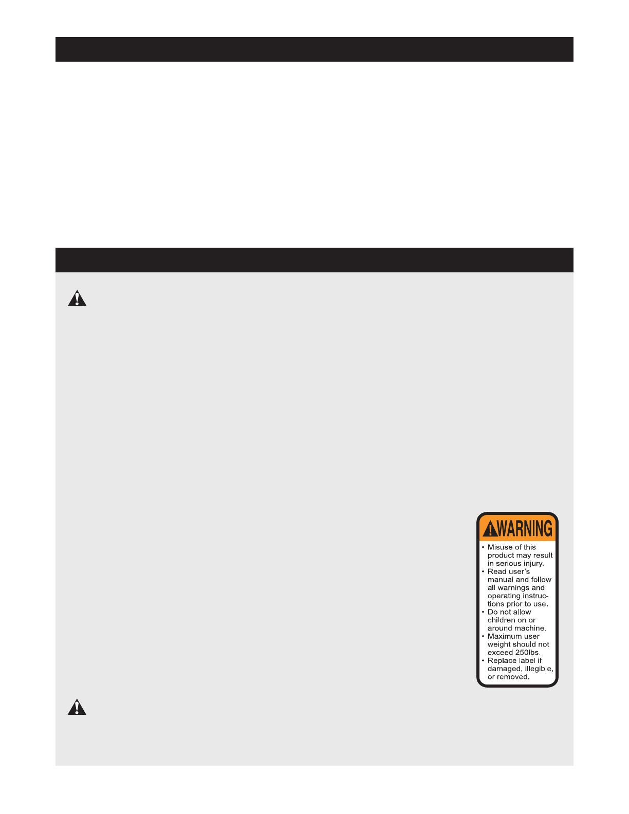
13.
The decal shown at the
right has been
placed on
the exercise cycle in the
location shown on page 3.
If the decal is missing or
illegible, call toll-free
1-877-994-4999, Monday
through Friday, 6 a.m.
until 6 p.m. Mountain
Time, and order a free
replacement decal. Apply
the replacement decal in
the location shown.
3
BEFORE YOU BEGIN
Congratulations for selecting the new REEBOK
®
RT
245 exercise cycle. Cycling is one of the most effec-
tive exercises for increasing cardiovascular fitness,
building
endurance, and toning the entire body. The
R
T 245 exercise cycle offers an impressive array of
features designed to let you enjoy this healthful exer-
cise in the comfort and privacy of your home.
For your benefit, read this manual carefully before
you use the exercise cycle. If you have questions
after reading this manual, please call our Customer
Service Department toll-free at 1-877-994-4999,
Monday through Friday, 6 a.m. until 6 p.m. Mountain
Time (excluding holidays). To help us assist you,
please mention the product model number and serial
number when calling.
The model number is
RBEX49840. The serial number can be found on a
decal attached to the exercise cycle (see the front
cover of this manual for the location of the decal).
Before reading further, please familiarize yourself with
the parts that are labeled in the drawing below.
Handgrip Pulse Sensor
Fan
Handlebar
BACK
Seat
Seat Post
Seat Knob
Side Shield
Leveling Pad
Wheel
Pedal with Strap
*No water bottle is included
Console
Bookrack
RIGHT SIDE
FRONT
WARNING DECAL
Water Bottle Holder*
4
Place all parts of the exercise cycle in a cleared area and remove the packing materials. Do not dispose of the
packing materials until assembly is completed.
Assembly requires your own adjustable wrench and phillips screwdriver .
P
ART CHART
Use the part drawings below to identify the small parts used in assembly. The number in parenthesis below
each drawing refers to the key number of the part, from the PART LIST on page 22. The second number refers
to the quantity used in assembly.
Note: Some small parts may have been pre-assembled for shipping. If a
part is not in the parts bag, check to see if it has been pre-assembled.
M8 x 25mm Button
Screw (19)–7
M10 x 92mm Carriage Bolt (62)–2
M10 x 105mm Carriage Bolt (64)–2
M6 x 8mm
Screw (26)–2
M8 Split Washer
(28)–11
M4 x 16mm
Screw (21)–4
M4 x 25mm
Screw (20)–2
M10 Nylon
Locknut (48)–4
M8 Nylon
Locknut (56)–4
M4 x 19mm
Screw (59)–2
ASSEMBLY
5
1. Identify the Front Stabilizer (2), which has Wheels
(17) attached to one side.
Attach the Front Stabilizer
to the Frame (1) with two M10 x 92mm Carriage
Bolts (62) and two M10 Nylon Locknuts (48).
2. Attach the Rear Stabilizer (3) to the Frame (1) with
two M10 x 105mm Carriage Bolts (64) and two M10
Nylon Locknuts (48).
3. While another person holds the Handlebar Post (6)
near the Frame (1), connect the Upper Wire
Harness (16) to the Lower Wire Harness (24). Next,
pull the excess Upper Wire Harness out of the top of
the Handlebar Post, and insert the Handlebar Post
into the Frame. Be careful not to pinch the Wire
Harnesses.
Slide the Round Collar (13) down the Handlebar
Post (6) and press it into the Frame (1). Attach the
Round Collar with an M6 x 8mm Screw (26).
Note: There are two sets of holes in the
Handlebar Post (6) so that it can be attached at
either of two heights. Attach the Handlebar Post to
the Frame (1) at the desired height with four M8 x
25mm Button Screws (19) and four M8 Split
Washers (28).
1
64
48
3
3
13
26
19
28
28
1
19
16
24
6
62
48
1
2
1
2
48
17
6
4. While another person holds the Handlebar (7) near
the Handlebar Post (6), feed the Upper Wire
Harness (16) and the Pulse Sensor W
ire (45) up
through the indicated hole in the Handlebar. Attach
the Handlebar to the Handlebar Post with three M8
x 25mm Button Screws (19) and three M8 Split
Washers (28).
6. Insert the Bookrack (8) into the slots in the Console
(9). Attach the Bookrack to the Console with two M4
x 25mm Screws (20). Be careful not to pinch the
wires in the Console.
8
20
9
4
6
7. While another person holds the Console (9) near
the Handlebar (7), connect the Pulse Sensor Wire
(45) and the Upper W
ire Harness (16) to the corre
-
sponding wires on the Console.
Insert all excess wiring down into the Handlebar
Post (6). Attach the Console (9) to the Handlebar
(7) with four M4 x 16mm Screws (21). Be careful
not to pinch the Pulse Sensor W
ires (45) or the
Upper Wire Harness (16).
7
6
Console
Wires
9
21
21
7
6
28
19
19
28
16
7
Hole
45
16
45
5. The Console (9) requires four “D” batteries (not
included); alkaline batteries are recommended.
Press the indicated tab on the battery cover and
remove the cover. Press four batteries into the bat-
tery clips;
make sure that the batteries are orient
-
ed as shown by the markings inside of the bat
-
tery clips. Then, reattach the battery cover.
9
Battery
Cover
Batteries
5
7
9. Identify the Left Pedal (40); the threaded shaft on
each Pedal is marked with an “L” for “left” or an “R”
for “right.” Using an adjustable wrench, firmly tight-
en the Left Pedal counterclockwise into the Crank
Assembly (33). Tighten the Right Pedal (not shown)
clockwise into the Crank Assembly. Important:
Tighten both Pedals as firmly as possible. After
using the exercise cycle for one week, retighten
the Pedals. For best performance, the Pedals
must be kept tightened.
Identify the Left Pedal Strap (41), which is marked
with an “L.” Attach the Left Pedal Strap to the Left
Pedal (40), and adjust the Left Pedal Strap to the
desired position. Attach and adjust the Right Pedal
Strap (not shown) in the same way.
33
40
41
9
1
1.
Make sure that all parts are properly tightened before you use the exercise cycle. Note: Some hard
-
ware may be left over after assembly is completed. Place a mat under the exercise cycle to protect the
floor or carpet.
10.
Attach the W
ater Bottle Holder (63) to the Frame (1)
with two M4 x 19mm Screws (59).
Note:
The water
bottle holder is designed to be used with your own
water bottle.
59
63
10
8. Attach the Seat (12) to the Seat Post (11) with four
M8 Nylon Locknuts (56) and four M8 Split Washers
(28).
Note: The Nylon Locknuts and Split
Washers may be pre-attached to the Seat.
Turn the Seat Knob (31) counterclockwise two or
three turns to loosen it. Next, pull the Knob, insert
the Seat Post (11) into the Frame (1), and then
release the Knob. Slide the Round Collar (13) down
the Seat Post and press it into the Frame. Attach
the Round Collar to the Frame with an M6 x 8mm
Screw (26). Move the Seat Post up and down
slightly until the pin on the Knob snaps into one
of the holes in the Seat Post. Then, turn the Knob
clockwise until it is tight.
12
13
28
56
26
1
1
8
11
31
8
HOW T
O
ADJUST THE HEIGHT OF THE SEA
T
For effective exercise, the seat should be at the proper
height. As you pedal, there should be a slight bend in
your knees when the pedals are in the lowest position.
To adjust the seat, first turn the seat knob counter-
clockwise several
turns to loosen it.
Next, pull the knob,
slide the seat post
up or down as
desired, and then
release the knob.
Move the seat
post up or down
slightly to make
sure that it locks
into place. Turn
the knob clockwise
to retighten it.
HOW T
O
ADJUST THE HANDLEBARS
The handlebars can be adjusted to either of two
heights. To adjust the handlebars, see assembly step
3 on page 5.
HOW TO ADJUST THE PEDAL STRAPS
To adjust the pedal
straps, first pull the
ends of the straps
off the tabs on the
pedals. Press the
straps back onto
the tabs using dif-
ferent holes in the
straps.
Tab
Seat
Seat
Knob
Seat Post
EXERCISE CYCLE OPERATION
HOW TO INSTALL THE RECEIVER FOR THE OPTIONAL CHEST PULSE SENSOR
If you purchase the optional chest pulse sensor (see page
19), follow the steps below to install the receiver
included with the chest pulse sensor.
1. See assembly step 5 on page 6, and remove the two
M4 x 25mm Screws (not shown) and the Bookrack (8).
Next, look under the console and locate the three indi-
cated screws (not shown). Remove the three screws.
Do not remove the screws attaching the Console to
the Handlebar (7).
2. Carefully lift the top of the Console (9) as shown. Using
the two small screws included with the chest pulse sen-
sor, attach the receiver to the indicated plastic posts on
the Console. Make sure that the receiver is turned
exactly as shown. Connect the wire on the receiver to
the indicated wire on the Console.
See step 1 above. Lower the top of the Console (9).
Make sure that no wires are pinched. Reattach the
top of the Console with the three screws removed in
step 1. See assembly step 5 on page 6, and reattach
the Bookrack (8) with the two M4 x 25mm Screws (not
shown). Note: The remaining wires included with the
chest pulse sensor may be discarded.
Posts
Wire
8
7
9
9
1
Receiver
2
Screws
Screws
Strap
9
FEATURES OF THE CONSOLE
The advanced console offers a selection of features
designed to make your workouts more enjoyable and
effective. When the manual mode of the console is
selected, the resistance of the pedals can be changed
with the touch of a button. As you exercise, the con-
sole will provide continuous exercise feedback. You
can even measure your heart rate using the handgrip
pulse sensor.
Note: See page 19 for information
about an optional chest pulse sensor.
The console also offers six preset programs. Each pro-
gram automatically changes the resistance of the ped
-
als and prompts you to increase or decrease
your pace
as it guides you through an effective workout.
In addition, the console features two heart rate pro
-
grams that automatically change the resistance of the
pedals and prompt you to vary your pace to keep your
heart rate near a target heart rate as you exercise.
The console also features iFIT.com interactive technol-
ogy. Having iFIT.com interactive technology is like hav-
ing a personal trainer in your home. Using the included
audio cable, you can connect the exercise cycle to your
home stereo, portable stereo, computer, or VCR and
play special iFIT.com CD and video programs (iFIT.com
CDs and videocassettes are available separately).
iFIT.com CD and video programs automatically control
the resistance of the pedals and prompt you to vary
your pace as a personal trainer coaches you through
every step of your workout. High-energy music pro-
vides added motivation.
To purchase iFIT.com CDs
and videocassettes, call toll-free 1-877-994-4999.
With the exercise cycle connected to your computer,
you can also go to our W
eb site at www
.iFIT
.com and
access programs directly from the internet. Explore
www.iFIT.com for more information.
T
o use the manual mode of the console,
see page
10. T
o use a preset program,
see page 12. T
o use a
heart rate program,
see page 13. To use an
iFIT
.com CD or videocassette,
see page 18. T
o use
a program directly from our W
eb site,
see page 19.
Note: If there is a sheet of clear plastic on
the face of the console, remove the plastic.
10
HOW T
O USE THE MANUAL MODE
Begin pedaling to activate the console.
To activate the console, begin pedaling. After a
few seconds, the console displays will light. A
tone will then sound and the console will be
ready for use.
Select the manual mode.
When the power is
turned on, the
manual mode will
be selected. If you
have selected a
program or the
iFIT.com mode,
select the manual mode by pressing the Program
Select button repeatedly until a track appears in
the matrix.
Begin pedaling and change the resistance of
the pedals as desired.
As you pedal,
change the resis-
tance of the ped-
als by pressing the
Resistance but-
tons. There are
ten resistance lev-
els. Note: After the buttons are pressed, it will
take a moment for the pedals to reach the select-
ed resistance level.
Monitor your progress with the matrix and the
two displays.
The matrix
When the manual
mode or the
iFIT.com mode is
selected, the
matrix will show a
track representing
1/4 mile. As you exercise, the indicators around
the track will light, one at a time, until the entire
track is lit. The track will then darken and a new
lap will begin.
The upper dis-
play—The upper
display will show
the elapsed time,
the distance you
have pedaled, and
your pedaling pace, in revolutions per minute
(RPM). The display will change from one number
to the next every few seconds, as shown by the
indicators in the display. Note: When a program is
selected, the display will show the time
remaining
in the program instead of the elapsed time. Each
time the resistance of the pedals changes, the
display will show the resistance level.
If desired, you can
select a single
mode for continu-
ous display. Press
the left Mode button
repeatedly until the
desired mode indi-
cator is lit; make sure that the Scan indicator is
not lit.
The lower
display—The lower
display will show
the approximate
number of calories
you have burned
and your pedaling
speed. The display will change from one number
to the next every few seconds, as shown by the
indicators in the display. The display will also
show your heart rate (pulse) when you use the
handgrip pulse sensor or the optional chest pulse
sensor.
Note: The console
can show speed
and distance in
either miles or
kilometers. The let-
ters MPH or KPH
will appear in the
lower display to show which unit of measurement
is selected. To change the unit of measurement,
first hold down the Program Select button for a few
seconds.
An E (for English) or an M (for metric) will
appear in the lower display. Press the Resistance
+ button to change the unit of measurement.
Then,
press the Cooling Fan button. Note: When the bat
-
teries are replaced, it may be necessary to rese-
lect the desired unit of measurement.
If desired, you can select a single mode for con-
tinuous display. Press the right Mode button
repeatedly until the desired mode indicator is lit;
make sure that the Scan indicator is not lit.
4
3
2
1
11
Measure your heart rate if desired.
You can measure your heart rate using either the
handgrip pulse sensor or the optional chest pulse
sensor. Note: If you hold the handgrip pulse
sensor and wear the chest pulse sensor at the
same time, the console will not display your
heart rate accurately
.
If there are
thin sheets of
plastic on the
metal con-
tacts on the
handgrip
pulse sensor,
peel off the
plastic.
To
measure your
heart rate, hold the contacts; your palms must be
resting on the contacts closest to you, and your
fingers must be touching the opposite contacts.
Avoid moving your hands.
When your pulse
is detected, the
heart-shaped indi-
cator in the lower
display will flash
each time your
heart beats, and
your heart rate will be shown. For the most accu-
rate heart rate reading, hold the contacts for at
least 15 seconds.
Note: If you continue to hold the pulse sensor, the
lower display will show your heart rate for up to
30 seconds.
The display will then show your heart
rate along with the other modes.
If your heart rate is not shown, make sure that
your hands are positioned as described. Avoid
moving your hands excessively or squeezing the
metal contacts too tightly. For optimal performance,
periodically clean the metal contacts using a soft
cloth; never use alcohol, abrasives, or chemicals.
Turn on the fan if desired.
To turn on the fan at low speed, press the Cooling
Fan button. To turn on the fan at high speed,
press the button a second time. To turn off the
fan, press the button a third time. Note: If the fan
is turned on but the pedals are not moved for thir-
ty seconds, the fan will automatically turn off.
When you are finished exercising, the console
will automatically turn off.
If the pedals are not moved for a few seconds, a
tone will sound, the console will pause, and the
upper display will begin to flash.
If the pedals are not moved for about five min-
utes, the console will turn off and the displays will
be reset.
7
6
5
Contacts
12
HOW T
O USE PRESET PROGRAMS
Begin pedaling to activate the console.
See step 1 on page 10.
Select one of the six preset programs.
When the power is
turned on, the
manual mode will
be selected. To
select a preset
program, press the
Program Select
button repeatedly until “P1,” “P2,” “P3,” “P4,”
“P5,” or “P6” appears in the lower display.
When a preset program is selected, the matrix
will show the first six resistance settings of the
program.
Press the Program Start button or begin
pedaling to start the program.
Each program is divided into several time seg-
ments of different lengths. One resistance setting
is programmed for each segment. (The same
resistance setting may be programmed for two or
more consecutive segments.)
The resistance
setting for the first
segment will be
shown in the flash-
ing Current
Segment column
of the matrix. The
resistance settings
for the next five
segments
will be shown in the columns to the
right.
When only three seconds remain in the first seg-
ment of the program
,
a series of tones will sound;
all resistance settings will then move one column
to the left. The resistance setting for the second
segment will then be shown in the flashing
Current Segment column and the resistance of
the pedals will automatically change to the resis-
tance setting for the second segment.
The program will continue until the resistance set-
ting for the last segment is shown in the Current
Segment column of the matrix and no time
remains in the program.
Note: During the program, you can override the
resistance setting for the current segment by
pressing the Resistance buttons. However, when
the next segment begins, the resistance will auto-
matically change if a different resistance setting is
programmed for the next segment. If you stop
pedaling for several seconds, a tone will sound
and the program will pause. To restart the pro-
gram, simply resume pedaling.
Use the pace (RPM) guide.
During preset pro-
grams, the pace
guide will prompt
you to increase or
decrease your ped-
aling pace. When
one of the indica-
tors on the left side
of the pace guide
lights, increase
your pace; when
one of the indica-
tors on the right side lights, decrease your pace.
When the center indicator lights, maintain your
current pace.
Important: The pace settings of
the program are intended only to provide a
goal. Make sure to pedal at a pace that is
comfortable for you.
Monitor your progress with the two displays.
See step 4 on page 10.
Measure your heart rate if desired.
See step 5 on page 1
1.
Turn on the fan if desired.
See step 6 on page 1
1.
When you are finished exercising, the console
will automatically turn off.
See step 7 on page 11.
8
7
6
5
4
3
2
1
Current Segment
13
HOW T
O USE HEART RATE PROGRAMS
Heart rate program 1 is designed to keep your heart
rate between 60% and 85% of your estimated maxi-
mum heart rate while you exercise. Note: Your maxi-
mum
heart rate is estimated by subtracting your age
from 220. For example, if you are 30 years old, your
estimated maximum heart rate is 190 (220 – 30 =
190).
Heart rate program 2 will keep your heart rate near a
target heart rate that you select.
Follow the steps below to use a heart rate program.
Begin pedaling to activate the console.
See step 1 on page 10.
Select one of the heart rate programs.
To select a heart
rate program,
press the Program
Select button
repeatedly until
“H1” or “H2”
appears in the
lower display.
If you selected
heart rate program
1, the matrix will
show the first six
target heart rate
settings of the pro-
gram.
If you selected
heart rate program
2, a heart symbol
will appear in the
matrix.
If you selected heart rate program 1, go to
step 3. If you selected heart rate program 2,
go to step 4.
Enter your age.
When heart rate
program 1 is
selected, you must
enter your age. If
you have already
entered your age,
press the Enter
(Program Start)
button and go to
step 5. If you have
not entered your
age, press the + or
– button repeatedly to enter your age, and then
press the Enter button. Note: Once you have
entered your age, it will be saved in memory.
Enter a target heart rate.
When heart rate
program 2 is
selected, you must
enter a target heart
rate. (See the heart
rate chart on page
21 for heart rate
guidelines.) To
enter a target heart
rate, press the + or
– button repeated-
ly, and then press
the Enter (Program Start) button.
Hold the handgrip pulse sensor or wear the
optional chest pulse sensor.
To use a heart rate program, you must hold the
handgrip pulse sensor or wear the optional chest
pulse sensor
. If you use the handgrip pulse sen
-
sor, it is not necessary to hold the handgrips con-
tinuously during the program. However, you
should hold the handgrips frequently for the pro-
gram to operate properly.
Each time you hold
the handgrips, keep your hands on the metal
contacts for at least 30 seconds.
Note: When
you are not holding the handgrips, the letters
“PLS” will appear in the lower display instead of
your heart rate.
5
4
3
2
1
14
Begin pedaling.
Each heart rate program is divided into 30 one-
minute segments. One target heart rate is pro-
grammed for each segment. Note:
The same tar-
get heart rate may be programmed for two or
more consecutive segments. If heart rate pro-
gram 2 is selected, the same target heart rate is
programmed for all segments.
If heart rate pro-
gram 1 is select-
ed,
the target
heart rate setting
for the first seg-
ment will be
shown in the
flashing Current
Segment column
of the matrix. The target heart rate settings for the
next five segments will be shown in the columns
to the right. When only three seconds remain in
the first segment of the program, a series of
tones will sound;
all target heart rate settings will
then move one column to the left. The target
heart rate setting for the second segment will
then be shown in the flashing Current Segment
column.
If heart rate program 2 is selected, the same
target heart rate is programmed for all segments;
therefore, the target heart rate settings will not be
shown in the matrix. When only three seconds
remain in the first segment of the program,a
series of tones will sound and the time will flash
in the right display.
As you pedal, the console will regularly compare
your heart rate to the target heart rate. If your
heart rate is too far below or above the target
heart rate, the resistance of the pedals will auto
-
matically increase or decrease to being your heart
rate closer to the target heart rate.
The pace guide
will help you to
maintain a con
-
stant pace during
the program. When
one of the indica-
tors on the left side
of the pace guide
lights, increase
your pace; when
one of the indica-
tors on the right
side lights, decrease your pace. When the center
indicator lights, maintain your current pace.
Important: The pace settings of the program
are intended only to provide a goal. Make
sure to pedal at a pace that is comfortable for
you.
The program will continue until the target heart
rate setting for the last segment is shown in the
Current Segment column of the matrix and no
time remains in the program.
Note: During the program, you can manually
change the resistance setting, if desired, by
pressing the Resistance buttons. However, when
the console compares your heart rate to the tar-
get heart rate, the resistance may automatically
change. If you stop pedaling for several seconds,
a tone will sound and the program will pause. To
restart the program, simply resume pedaling.
Monitor your progress with the two displays.
See step 4 on page 10.
Turn on the fan if desired.
See step 6 on page 11.
When you are finished exercising, the con
-
sole will automatically turn off.
See step 7 on page 11.
9
8
7
6
Current Segment
15
HOW TO CONNECT YOUR CD PLAYER, VCR,
OR COMPUTER
T
o use iFIT.com CDs
, the exercise cycle must be con
-
nected to your portable CD player, portable stereo,
home stereo, or computer with CD player. See pages
15 and 16 for connecting instructions. To use iFIT.com
videocassettes, the exercise cycle must be connected
to your VCR. See page 17 for connecting instructions.
To use iFIT.com programs directly from our Web
site, the exercise cycle must be connected to your
home computer. See page 16 for connecting instruc-
tions.
HOW TO CONNECT YOUR PORTABLE CD PLAYER
Note: If your CD player has separate LINE OUT and
PHONES jacks, see instruction A below. If your CD
player has only one jack, see instruction B.
A. Plug one end of the audio cable into the jack
beneath the console. Plug the other end of the
cable into the LINE OUT jack on your CD player.
Plug your headphones into the PHONES jack.
B. Plug one end of the audio cable into the jack
beneath the console. Plug the other end of the
cable into a 1/8”
Y-adapter (available at electronics
stores). Plug the Y-adapter into the PHONES jack
on your CD player. Plug your headphones into the
other side of the Y-adapter.
HOW TO CONNECT YOUR PORTABLE STEREO
Note: If your stereo has an RCA-type
AUDIO OUT
jack, see instruction A below. If your stereo has a
1/8” LINE OUT jack, see instruction B. If your
stereo has only a PHONES jack, see instruction C.
A. Plug one end of the audio cable into the jack
beneath the console. Plug the other end of the cable
into the adapter. Plug the adapter into an AUDIO
OUT jack on your stereo.
B. Plug one end of the audio cable into the jack
beneath the console. Plug the other end of the
cable into the LINE OUT jack on your stereo. Do
not use the adapter.
C. Plug one end of the audio cable into the jack
beneath the console. Plug the other end of the
cable into a 1/8” Y-adapter (available at electronics
stores). Plug the Y-adapter into the PHONES jack
on your stereo. Plug your headphones into the
other side of the Y-adapter.
LINE OUT
PHONES
LINE OUT
PHONES
Audio
Cable
Head-
phones
A
PHONES
PHONES
Audio
Cable
1/8”
Y-adapter
Headphones
B
AUDIO OUT
RIGHT
LEFT
PHONES
Audio
Cable
C
1/8”
Y-adapter
Headphones
Audio Cable
Adapter
A, B
16
HOW TO CONNECT YOUR HOME STEREO
Note: If your stereo has an unused LINE OUT jack,
see instruction A below. If the LINE OUT jack is
being used, see instruction B.
A. Plug one end of the audio cable into the jack
beneath the console. Plug the other end of the
cable into the adapter. Plug the adapter into the
LINE OUT jack on your stereo.
B. Plug one end of the audio cable into the jack
beneath the console. Plug the other end of the
cable into the adapter. Plug the adapter into an
RCA Y-adapter (available at electronics stores).
Next, remove the wire that is currently plugged into
the LINE OUT jack on your stereo and plug the
wire into the unused side of the Y-adapter. Plug the
Y-adapter into the LINE OUT jack on your stereo.
HOW TO CONNECT YOUR COMPUTER
Note:
If your computer has a 1/8” LINE OUT jack,
see instruction A. If your computer has only a
PHONES jack, see instruction B.
A. Plug one end of the audio cable into the jack
beneath the console. Plug the other end of the
cable into the LINE OUT jack on your computer.
B. Plug one end of the audio cable into the jack
beneath the console. Plug the other end of the
cable into a 1/8” Y-adapter (available at electronics
stores). Plug the Y-adapter into the PHONES jack
on your computer. Plug your headphones or speak-
ers into the other side of the Y-adapter.
CD
VCR
Amp
LINE OUT
LINE OUT
Audio Cable
Adapter
A
CD
VCR
Amp
LINE OUT
Audio
Cable
RCA
Y-adapter
W
ire removed from
LINE OUT
jack
B
Adapter
LINE OUT
Audio
Cable
A
PHONES
Audio Cable
B
1/8”
Y-adapter
Headphones/Speakers
17
HOW TO CONNECT YOUR VCR
Note: If your VCR has an unused
AUDIO OUT jack,
see instruction A below. If the AUDIO OUT jack is
being used, see instruction B. If you have a TV
with a built-in VCR, see instruction B. If your VCR
is connected to your home stereo, see HOW TO
CONNECT YOUR HOME STEREO on page 16.
A. Plug one end of the audio cable into the jack
beneath the console. Plug the other end of the
cable into the adapter. Plug the adapter into the
AUDIO OUT jack on your VCR.
B. Plug one end of the audio cable into the jack
beneath the console. Plug the other end of the
cable into the adapter
. Plug the adapter into an
RCA Y-adapter (available at electronics stores).
Next, remove the wire that is currently plugged into
the AUDIO OUT jack on your VCR and plug the
wire into the unused side of the Y-adapter. Plug the
Y-adapter into the AUDIO OUT jack on your VCR.
AUDIO OUT
RIGHT
LEFT
VIDEO AUDIO
ANT
. IN
RF OUT
IN
OUT
CH
3
4
Audio Cable
Adapter
A
VIDEO AUDIO
ANT
. IN
RF OUT
IN
OUT
CH
34
A
Audio Cable
Adapter
B
Wire removed from
AUDIO OUT jack
RCA Y-adapter
18
To use iFIT.com CDs or videocassettes, the exercise
cycle must be connected to your portable CD player,
portable stereo, home stereo, computer with CD play-
er, or VCR. See HOW TO CONNECT YOUR CD
PLA
YER, VCR, OR COMPUTER on pages 15 to 17.
To purchase iFIT.com CDs and videocassettes, call
toll-free 1-877-994-4999.
Follow the steps below to use an iFIT.com CD or
video program.
Begin pedaling to activate the console.
See step 1 on page 10.
Select the iFIT.com mode.
When the console is
turned on, the man-
ual mode will be
selected. To select
the iFIT.com mode,
press the iFIT.com
button. The indicator
on the button will light.
Insert the iFIT.com CD or videocassette.
If you are using an iFIT.com CD, insert the CD
into your CD player. If you are using an iFIT.com
videocassette, insert the videocassette into your
VCR.
Press the play button on your CD player or
VCR.
A
moment after the play button is pressed, your
personal trainer will begin guiding you through
your workout. Simply follow your personal trainer’s
instructions.
The program will function in almost the same way
as a preset program (see steps 3 and 4 on page
12). However, an electronic “chirping” sound will
alert you when the resistance of the pedals and/or
the target pace is about to change.
Note: If the resistance of the pedals and/or the
target pace does not change when a “chirp” is
heard:
• Make sure that the indicator above the
iFIT.com button is lit.
Adjust the volume of your CD player or VCR.
If the volume is too high or too low, the con-
sole may not detect the program signals.
• Make sure that the audio cable is properly
connected and that it is fully plugged in.
Monitor your progress with the two displays.
See step 4 on page 10.
Measure your heart rate if desired.
See step 5 on page 11.
Turn on the fan if desired.
See step 6 on page 11.
When you are finished exercising, the console
will automatically turn off.
See step 7 on page 11.
8
7
6
5
4
3
2
1
HOW TO USE IFIT.COM CD AND VIDEO
PROGRAMS
19
HOW TO USE PROGRAMS DIRECTLY FROM
OUR WEB SITE
Our Web site at www.iFIT.com allows you to play
iFIT.com programs directly from the internet. To use
programs from our Web site, the exercise cycle must
be connected to your home computer. See HOW TO
CONNECT YOUR COMPUTER on page 16. In addi-
tion, you must have an internet connection and an
internet service provider. A list of specific system
requirements is found on our Web site.
Follow the steps below to use a program from our
Web site.
Begin pedaling to activate the console.
See step 1 on page 10.
Select the iFIT.com mode.
When the console is
turned on, the manu-
al mode will be
selected. To select
the iFIT.com mode,
press the iFIT.com
button. The indicator
on the button will light.
Go to your computer and start an internet
connection.
Start your Web browser, if necessary, and go
to our Web site at www.iFIT.com.
Follow the desired links on our W
eb site to
select a program.
Read and follow the on-line instructions for using
a program.
Follow the on-line instructions to start the
program.
When you start the program, an on-screen count-
down will begin.
Return to the exercise cycle and begin
pedaling.
When the on-screen countdown ends, the pro-
gram will begin. The program will function in
almost the same way as a
preset program (see
steps 3 and 4 on page 12). However, an electronic
“chirping” sound will alert you when the resistance
of the pedals and/or the target pace is about to
change.
Monitor your progress with the two displays.
See step 4 on page 10.
Measure your heart rate if desired.
See step 5 on page 11.
Turn on the fan if desired.
See step 6 on page 11.
When you are finished exercising, the console
will automatically turn off.
See step 7 on page 11.
THE OPTIONAL CHEST PULSE SENSOR
The optional chest pulse sensor provides hands-free
operation and continuously monitors your heart rate
during your workouts. To purchase the optional
chest pulse sensor, call toll-free 1-877-994-4999.
11
10
9
8
7
6
5
4
3
2
1
20
Inspect and properly tighten all parts of the exercise
cycle regularly. The exercise cycle can be cleaned
with a soft, damp cloth. To prevent damage to the
console, keep liquids away from the console and keep
the console out of direct sunlight.
TIGHTENING THE PEDALS
For best performance, regularly tighten both pedals.
CONSOLE TROUBLESHOOTING
If the console display becomes dim, the batteries
should be replaced. See assembly step 5 on page 6
for replacement instructions. If the console does not
display your heart rate when you use the handgrip
pulse sensor, see step 5 on page 13.
HOW TO LEVEL THE EXERCISE CYCLE
If the exercise
cycle does not sit
flat on the floor,
turn one or both
of the leveling
pads until the
exercise cycle is
level.
HOW TO ADJUST THE DRIVE BELT
If you can feel the pedals slip while you are pedaling,
even when the resistance is at the highest level, the
Drive Belt (not shown) may need to be adjusted. To
adjust the Drive Belt, the Right Side Shield (5) must
first be removed. Remove the indicated M4 x 38mm
Screws (30) and M4 x 16mm Screws (21) from the
Right Side Shield. Using an adjustable wrench, turn
the Right Pedal (37) counterclockwise and remove it.
Next, turn the Crank (33) so that it is pointing toward
the front of the exercise cycle, and then slide off the
Right Side Shield.
Next, turn the
indicated M8 x
40mm Screw
(58) until the
Drive Belt (69)
is properly
tightened.
Then, reattach
the right side
shield and the
right pedal.
HOW TO ADJUST THE REED SWITCH
If the console does not display correct feedback, the
reed switch should be adjusted. See HOW TO
ADJUST THE DRIVE BELT at the left. Remove the
indicated M4 x 38mm Screws (30) from the Right Side
Shield (5) and the M4 x 16mm Screws (not shown)
from the Left Side Shield (4). Using an adjustable
wrench, turn the Left Pedal (not shown) clockwise and
remove it. Turn the Crank (33) so that it is pointing
toward the front of the exercise cycle, and then slide
off the Left Side Shield.
Locate the
Reed Switch
(44). Turn the
Crank (33)
until the
Magnet (18) is
aligned with
the Reed
Switch.
Loosen, but
do not
remove, the
indicated M4 x
16mm Screw
(21). Slide the
Reed Switch slightly closer to or away from the
Magnet. Then, retighten the Screw. Turn the Left
Crank
Arm for a moment. Repeat until the console
displays correct feedback. When the Reed Switch is
correctly adjusted, reattach the left side shield and the
left pedal.
MAINTENANCE AND TROUBLESHOOTING
Leveling
Pads
30
21
5
4
37
58
33
69
27
21
44
18
  • Page 1 1
  • Page 2 2
  • Page 3 3
  • Page 4 4
  • Page 5 5
  • Page 6 6
  • Page 7 7
  • Page 8 8
  • Page 9 9
  • Page 10 10
  • Page 11 11
  • Page 12 12
  • Page 13 13
  • Page 14 14
  • Page 15 15
  • Page 16 16
  • Page 17 17
  • Page 18 18
  • Page 19 19
  • Page 20 20
  • Page 21 21
  • Page 22 22
  • Page 23 23
  • Page 24 24

Pro-Form GT 120 User manual

Category
Fitness, gymnastics & weight training
Type
User manual

Ask a question and I''ll find the answer in the document

Finding information in a document is now easier with AI