
1
Troubleshooting & Service for GL/GS Systems
50 Hz

2
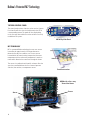
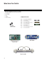
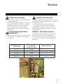
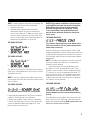
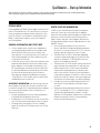
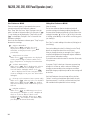
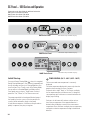
Balboa’s Patented M7 Technology
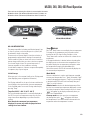
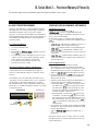
TOPSIDE CONTROL PANEL
The control panel activates functions at the touch of a button.
Each function will echo from the circuit board to the LCD in
a corresponding manner. The panel will also display diag-
nostic messages that enable the service technician to easily
troubleshoot the system.
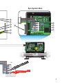
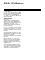
M7 TECHNOLOGY
M7 is a patented Balboa technology that uses two sensors
inserted at the opposite ends of the heater element to
determine flow, dry fire conditions, etc. The two sensors
located within the heater housing compare the inlet water
temperature with the outlet water temperature. It works no
matter which direction the water flows through the heater.
The sensors in combination with specific software allow the
spa to be controlled without the use of external pressure
switches, flow switches, or temperature sensors.
Panel Construction
GS500 with a Cut-a-way
View of the Heater
Sensor
Sensor
ML700 Top Side Panel
Cool
WarmTime
Mode/Prog
Blower
Jets 2
Light
Jets 1
F2
TL
F1
PL

3
Table of Contents
Balboa’s Patented M7 Technology . . . . . . . . . . . . . . . . . . . . . . . . . . . . . . . . . . . . . . . . . . . . . .2
Balboa Service Tools Checklist. . . . . . . . . . . . . . . . . . . . . . . . . . . . . . . . . . . . . . . . . . . . . .5
Balboa Service Parts Checklist . . . . . . . . . . . . . . . . . . . . . . . . . . . . . . . . . . . . . . . . . . . . . .6
Important Information -- Product Identification. . . . . . . . . . . . . . . . . . . . . . . . . . . . . . . . . . . . .7
Troubleshooting & Servicing Spa and Electrical Equipment . . . . . . . . . . . . . . . . . . . . . . . . . . . . . . .8
Wiring Checks . . . . . . . . . . . . . . . . . . . . . . . . . . . . . . . . . . . . . . . . . . . . . . . . . . . . . . . .9
230 Volt 50 Hz - Residual Current Devices (RCD’s) . . . . . . . . . . . . . . . . . . . . . . . . . . . . . . . . . . 14
Wiring Check for RCD and Service Disconnect. . . . . . . . . . . . . . . . . . . . . . . . . . . . . . . . . . . . 15
Diagnosing M7 Topside Control Panels . . . . . . . . . . . . . . . . . . . . . . . . . . . . . . . . . . . . . . . . . . 16
Some Troubleshooting Scenarios . . . . . . . . . . . . . . . . . . . . . . . . . . . . . . . . . . . . . . . . . . . . 18
Basic Control System Troubleshooting . . . . . . . . . . . . . . . . . . . . . . . . . . . . . . . . . . . . . . . . 19
Low Voltage . . . . . . . . . . . . . . . . . . . . . . . . . . . . . . . . . . . . . . . . . . . . . . . . . . . . . . . 19
Brown Outs . . . . . . . . . . . . . . . . . . . . . . . . . . . . . . . . . . . . . . . . . . . . . . . . . . . . . . . 19
Checking the System Power Input Fuse. . . . . . . . . . . . . . . . . . . . . . . . . . . . . . . . . . . . . . . . . 19
To Determine the Cause of a Blown Power Input Fuse. . . . . . . . . . . . . . . . . . . . . . . . . . . . . . . . . 20
Test the Amperage Draw . . . . . . . . . . . . . . . . . . . . . . . . . . . . . . . . . . . . . . . . . . . . . . . . 20
Spa Behavior -- Start-up Information. . . . . . . . . . . . . . . . . . . . . . . . . . . . . . . . . . . . . . . . . . 21
Priming Mode . . . . . . . . . . . . . . . . . . . . . . . . . . . . . . . . . . . . . . . . . . . . . . . . . . . . . . 21
General Information on filter times . . . . . . . . . . . . . . . . . . . . . . . . . . . . . . . . . . . . . . . . . . . 21
Heater Start up Information . . . . . . . . . . . . . . . . . . . . . . . . . . . . . . . . . . . . . . . . . . . . . . . 21
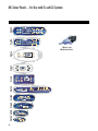
ML Series Panels -- For Use with EL and GL Systems . . . . . . . . . . . . . . . . . . . . . . . . . . . . . . . . 22
ML900
Panel Operation . . . . . . . . . . . . . . . . . . . . . . . . . . . . . . . . . . . . . . . . . . . . . . . . . 23
ML700
Panel Operation . . . . . . . . . . . . . . . . . . . . . . . . . . . . . . . . . . . . . . . . . . . . . . . . . 24
ML550, 551, 554
Panel Operation . . . . . . . . . . . . . . . . . . . . . . . . . . . . . . . . . . . . . . . . . . . 25
ML200, 240, 260, 400 Panel Operation. . . . . . . . . . . . . . . . . . . . . . . . . . . . . . . . . . . . . . . . . . 29
GL Series Mach 3 -- Persistent Memory & Power Up . . . . . . . . . . . . . . . . . . . . . . . . . . . . . . . . 33
GL, about Persistent Memory . . . . . . . . . . . . . . . . . . . . . . . . . . . . . . . . . . . . . . . . . . . . . . 33
Power Up Display Sequence, Software ID . . . . . . . . . . . . . . . . . . . . . . . . . . . . . . . . . . . . . . . 33
VL Series Panels -- For use with GS Systems . . . . . . . . . . . . . . . . . . . . . . . . . . . . . . . . . . . . . 34
GS Panel -- 500 Series and Operation . . . . . . . . . . . . . . . . . . . . . . . . . . . . . . . . . . . . . . . . . 36
GS Persistent Memory with VL Panels . . . . . . . . . . . . . . . . . . . . . . . . . . . . . . . . . . . . . . . . . 39
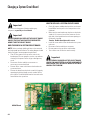
Changing a System Circuit Board . . . . . . . . . . . . . . . . . . . . . . . . . . . . . . . . . . . . . . . . . . . . 40
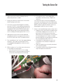
Testing the Sensor Set . . . . . . . . . . . . . . . . . . . . . . . . . . . . . . . . . . . . . . . . . . . . . . . . . . 41
Removing the Heater Assembly from a Spa System . . . . . . . . . . . . . . . . . . . . . . . . . . . . . . . . . 42
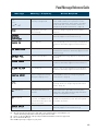
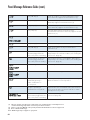
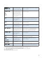
Panel Message Reference Guide . . . . . . . . . . . . . . . . . . . . . . . . . . . . . . . . . . . . . . . . . . . . 43

4
230 Volt / 50 Hz Residential Wiring Schematic with 2 Pole RCD Breaker Box . . . . . . . . . . . . . . . . . . . . 10
230 Volt / 50 Hz Residential Wiring Schematic with 4 Pole RCD Breaker Box . . . . . . . . . . . . . . . . . . . . 12
500DZ Series Panel . . . . . . . . . . . . . . . . . . . . . . . . . . . . . . . . . . . . . . . . . . . . . . . . . . . . . . 36
500SZ Series Panel. . . . . . . . . . . . . . . . . . . . . . . . . . . . . . . . . . . . . . . . . . . . . . . . . . . . . . . 36
500Z Series Panel . . . . . . . . . . . . . . . . . . . . . . . . . . . . . . . . . . . . . . . . . . . . . . . . . . . . . . . 36
53649 ML700 . . . . . . . . . . . . . . . . . . . . . . . . . . . . . . . . . . . . . . . . . . . . . . . . . . . . . . . . . . .6
Common Fuses Used. . . . . . . . . . . . . . . . . . . . . . . . . . . . . . . . . . . . . . . . . . . . . . . . . . . . . . .6
Four Pole RCD. . . . . . . . . . . . . . . . . . . . . . . . . . . . . . . . . . . . . . . . . . . . . . . . . . . . . . . . . . 14
Ground in System Enclosure . . . . . . . . . . . . . . . . . . . . . . . . . . . . . . . . . . . . . . . . . . . . . . . . . .8
GS500 Controller Board Part No. 22844 . . . . . . . . . . . . . . . . . . . . . . . . . . . . . . . . . . . . . . . . . . . .6
GS500 with a Cut-a-way View of the Heater . . . . . . . . . . . . . . . . . . . . . . . . . . . . . . . . . . . . . . . . .2
GS500Z Board. . . . . . . . . . . . . . . . . . . . . . . . . . . . . . . . . . . . . . . . . . . . . . . . . . . . . . . . . . 40
Heater Element Specifications Are Shown on the Heater Tube Label . . . . . . . . . . . . . . . . . . . . . . . . . .7
ML260, ML240, ML200 . . . . . . . . . . . . . . . . . . . . . . . . . . . . . . . . . . . . . . . . . . . . . . . . . . . . . 29
ML400 . . . . . . . . . . . . . . . . . . . . . . . . . . . . . . . . . . . . . . . . . . . . . . . . . . . . . . . . . . . . . . 29
ML550 . . . . . . . . . . . . . . . . . . . . . . . . . . . . . . . . . . . . . . . . . . . . . . . . . . . . . . . . . . . . . . 25
ML551 . . . . . . . . . . . . . . . . . . . . . . . . . . . . . . . . . . . . . . . . . . . . . . . . . . . . . . . . . . . . . . 25
ML554 . . . . . . . . . . . . . . . . . . . . . . . . . . . . . . . . . . . . . . . . . . . . . . . . . . . . . . . . . . . . . . 25
ML700 Top Side Panel . . . . . . . . . . . . . . . . . . . . . . . . . . . . . . . . . . . . . . . . . . . . . . . . . . . . . .2
“Molex” Type, ML/GL Connector . . . . . . . . . . . . . . . . . . . . . . . . . . . . . . . . . . . . . . . . . . . . . . .7
On Every System, an Identification Label Is Placed on top of the Casing . . . . . . . . . . . . . . . . . . . . . . . .7
On Every System, a Wiring Diagram Is Placed Inside the Door . . . . . . . . . . . . . . . . . . . . . . . . . . . . . .7
Panel Construction. . . . . . . . . . . . . . . . . . . . . . . . . . . . . . . . . . . . . . . . . . . . . . . . . . . . . . . .2
“Phone Plug” RJ Type, VL/GS Connector . . . . . . . . . . . . . . . . . . . . . . . . . . . . . . . . . . . . . . . . . .7
Recommended Parts For Service Calls . . . . . . . . . . . . . . . . . . . . . . . . . . . . . . . . . . . . . . . . . . . .6
Service Tools Required . . . . . . . . . . . . . . . . . . . . . . . . . . . . . . . . . . . . . . . . . . . . . . . . . . . . .5
Terminal Block 1 & F6 Power Input Fuse on a GS500Z Board . . . . . . . . . . . . . . . . . . . . . . . . . . . . . . 19
Two Pole RCD. . . . . . . . . . . . . . . . . . . . . . . . . . . . . . . . . . . . . . . . . . . . . . . . . . . . . . . . . . 14
Diagrams (in alphabetical order)

5
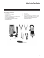
Balboa Service Tools Checklist
Service Tools Required
Ammeter (50A)UÊ
Balboa Six-in-one ScrewdriverUÊ
Digital Multi-meterUÊ
Padlock (to lock electrical disconnect during service)UÊ
Pliers: Slip Joint & Needle noseUÊ
Precision Thermometer - Digital Fever TypeUÊ
Quick CheckUÊ
TM
Test Kit
Silicone TubeUÊ
Small Wire CuttersUÊ
Two 3/8” Open End Wrenches (one wrench should be UÊ
ground down to 5/32” [0.1562”] thickness in order to
access the nut between the heater strap and
heater element connector)

6
Balboa Service Parts Checklist
Recommended Parts For Service Calls
Extra Board(s)UÊ
Extra Panel(s)UÊ
FusesUÊ
JumpersUÊ
Heater AssemblyUÊ
20618
JUMPER LOGIC
COMMON FUSES USED
30074 FUSE 1 AMP FAST BLOW GLASS
30075 FUSE 5 AMP FAST BLOW GLASS
30122 FUSE 10A BLOWER
30595 FUSE 10A POWER INPUT
30076 FUSE 15 AMP FAST BLOW CERAMIC
30596 FUSE 15A POWER INPUT
30142 FUSE 20A POWER INPUT
30123 FUSE 20A PUMP
30137 FUSE 25A POWER INPUT
21447 FUSE 25A POWER INPUT HIGH SURGE
30136 FUSE 30A POWER INPUT
Heater Assembly
53649 ML700
GS500 Controller Board
Part No. 22844
Cool
WarmTime
Mode/Prog
Blower
Jets 2
Light
Jets 1
F2
TL
F1
PL

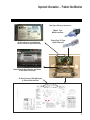
7
Two Types of Plug-in Connectors:
“Molex” Type,
ML/GL Connector
On Every System, an Identification
Label Is Placed on top of the Casing
Heater Element Specifications Are Shown
on the Heater Tube Label
On Every System, a Wiring Diagram
Is Placed Inside the Door
Important Information -- Product Identification
“Phone Plug” RJ Type,
VL/GS Connector

8
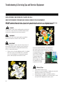
Troubleshooting & Servicing Spa and Electrical Equipment
DANGER
Risk of electric shock. Before working with any electrical
connections, make certain that the Main Power breaker
from the house breaker box has been turned off.
WARNING
All electrical work must be performed by a qualified
electrician and must conform to all local codes.
IMPORTANT
Due to the danger of severe electrical shock, locate all
power disconnects before servicing a spa. Precautions
must be taken whenever working with breaker boxes,
RCD’s, or service disconnects.
Always refer to the wiring diagram which is included UÊ
with each system on the inside of the system box
cover. Use this diagram for voltage measurement
points, and for proper reconnection of wires.
HIGH VOLTAGE CAN SERIOUSLY INJURE OR KILL!
ONLY EXPERIENCED TECHNICIANS SHOULD SERVICE THIS EQUIPMENT.
DO NOT remove the protective covers from any electrical enclosure, or attempt to service any
related electrical device, unless you are a qualified electrician or service professional.
Safety Tips
Keep children and pets away.UÊ
Be aware of your surroundings. Standing in water while UÊ
repairing a spa puts you at serious risk.
Avoid working in cramped or crowded conditions.UÊ
Consider placing a padlock on the service panel to lock UÊ
out anyone who might power up the system.
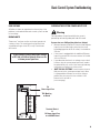
A terminal marked “GROUND” is provided within
the System Control Center enclosure. To reduce
the risk of electrical shock, connect this terminal
to the grounding terminal
of the electric supply panel
with a continuous green
insulated copper wire
equivalent in size to the
circuit conductors supplying
this equipment, but no
smaller than #12 AWG.
Ground in System Enclosure

9
Wiring Checks
WIRING CHECK PRECAUTIONS
When working in a system box always be aware that it UÊ
may contain high voltage.
Always keep your fingers and hand tools away from any UÊ
wiring or circuit board when the power is on. Touching
anything in these areas can result in serious injury.
All service calls, no matter how minor, should UÊ
include a complete wiring check, beginning with the
house breaker.
CHECK FOR LOOSE CONNECTIONS OR
DAMAGED WIRES
Make sure the power is off before you touch any wiring.UÊ
Once the power is off, carefully examine all wires for UÊ
cuts or defects.
SYSTEM BOX WIRE GAUGE CHECK
When inspecting the wiring for any control system, note
that connections for the incoming wires are clearly labeled
at the main terminal block.
30A service – minimum ten gauge copper wire.UÊ
These wires must connect the house breaker box,
through the local disconnect, to the main terminal block.
The wiring diagram inside the system box shows the main
terminal block as TB1.
IMPORTANT -- USE OF NON-COPPER WIRE
Using non-copper wire can be dangerous, and also can be
the cause of a spa’s malfunction. If non-copper wire
is used at any point, we do not recommend servicing the
spa until an electrician replaces it with the proper gauge
copper wire.
Tota
l
Ampere Rating o
f
Power Syste
m
Minimum wire size
U
se
C
o
pp
er
O
NLY,
w
ith 90
o
C
insulatio
n
Ampere Rating o
f
R
C
D
C
ircuit-breake
r
0
A to 1
6
A
#
12 AWG 2
0
1
6
A to 2
0
A
#10 AW
G
2
5
2
0
A to 24 A #10 AW
G
30
24 A to 2
8
A #8 AWG
35
2
8
A to
3
2
A
#8 AWG
40

10
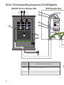
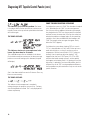
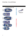
230 Volt / 50 Hz Residential Wiring Schematic with 2 Pole RCD Breaker Box
Outside Ground Rod
ON
ON
ON
ON
OFF
OFFOFF
OFF
OFF
OFFOFF
OFF
ON
ON
ON
ON
230VAC House Breaker Box
RCD Breaker Box
ON
OFF
Correct
Voltage
When Probes Are Placed Across
0v [1 - 3] [4 - 7] [5 - 9] [10 - 11]
207V - 253V [1 - 2] [2 - 3] [4 - 6] [5 - 8] [6 -7] [8 - 9] [10 - 12] [11 - 12]
207V - 253V [1 - 2] [2 - 3] [4 - 6] [5 - 8] [6 -7] [8 - 9] [10 - 12] [11 - 12]
C
orrec
t
V
o
l
tag
e
W
he
n Pr
obes
Ar
e
P
laced
A
c
r
oss
230 VAC
“Live Wire”
Neutral
+
Ground
7
6
9
8
10
11
12

11
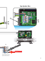
Spa System Box
TB1
HTR2
J101 J100
HTR1
G
N
J50
T1
J1
J2
J10
J57
J58
J71
10VAC
10VAC
J46
J25
J26
J72
J90
J28
J1A
J2A
J32
J52
J51
F6, T30A 480V
AV
OZONE PUMP 1
OPT. BLWR/PUMP 2
CIRC. PUMP
K1
K3K4
K6
E.GND
J47
G
N
G
N
G
N
J29
J23
G
N
J17/26
K2
K9
J20
GN
W2
1
2
3
4
W1
Balboa
BALBOA INSTRUMENTS, INC.
GS500Z
COPYRIGHT 2007
MADE IN U.S.A.
P/N 22015_B
J60
J44
J18
J7
J8
EXT RLY
TST
J6
SEN A
VACSEN B
J22
J43
AUX F
J18
J13
J11
J12
J19
F2
S1
SWITCHBANK A
K8
K5
C9
U4
F3A 250V
F7
F1
F10A 250V
F4, T0.2A 250V
F3
BROWN
LINE 2
BROWN
BROWN
LINE 1
BROWN
SERVICE 1
SERVICE 2
INPUT RATING
230V/16A 2 ERVICES
(REMOVE JUMPER A)
INPUT RATING
230V/32A 1 ERVICES
(REMOVE JUMPER A)
TB1
HTR2
J101 J100
HTR1
G
N
J50
T
J57
J58
J25
J26
J90
J28
J32
J52
J51
F6, T30A 480V
AV
OZONE PUMP 1
CIRC. PUMP
K3K4
J47
G
N
G
N
G
N
J29
J23
K2
K9
W2
W1
Balboa
BALBOA INSTRUMENTS, INC.
GS500Z
COPYRIGHT 2007
MADE IN U.S.A.
P/N 22015_B
F4, T0.2A 250V
Pb
BROWN
LINE 2
BROWN
BROWN
LINE 1
BROWN
SERVICE 1
SERVICE 2
INPUT RATING
230V/16A 2 ERVICES
(REMOVE JUMPER A)
INPUT RATING
230V/32A 1 ERVICES
(REMOVE JUMPER A)
3
5
1
2
4
Test for Voltages by placing
probes on these locations
BROWN
LINE 2
BROWN
LINE 1
SERVICE 1
SERVICE 2
INPUT RATING
230V/16A 2 ERVICES
(REMOVE JUMPER A)
INPUT RATING
230V/32A 1 ERVICES
(REMOVE JUMPER A)
BLUE
BLUE
TB1
Electric Installation Euro_2-Pole_RCD_092508.eps

12
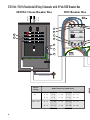
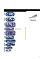
230 Volt / 50 Hz Residential Wiring Schematic with 4 Pole RCD Breaker Box
230 VAC
“Live Wire”
Neutral
+
Ground
Outside Ground Rod
ON
ON
ON
ON
OFF
OFFOFF
OFF
OFF
OFFOFF
OFF
ON
ON
ON
ON
230VAC House Breaker Box
RCD Breaker Box
ON
OFF
1
2
3
4
N
N
N
N
Correct
Voltage
When Probes Are Placed Across
0v [1 - 5] [6 - 8] [7 - 14] [7 - 17] [16 - 17]
[3 - 5] [6 - 9] [7 - 15] [7 - 18] [16 - 18]
207V - 253V [2 - 5] [6 - 10] [7 - 12] [16 - 19] [17 - 19]
[4 - 5] [6 - 11] [7 - 13] [16 - 20] [17 - 20]
C
orrec
t
V
olta
ge
Wh
en Pro
b
es Are P
l
ace
d
Acros
s
[
6 - 10
]
[6 - 11]
[
6 - 8
]
[
6 - 9
]
[
16 - 19
]
[16 - 20]
[
7 - 17
]
[
7 - 18
]
16
17
20
18
19
10
11
12
13

13
Spa System Box
TB1
HTR2
J101 J100
HTR1
G
N
J50
T1
J1
J2
J10
J57
J58
J71
10VAC
10VAC
J46
J25
J26
J72
J90
J28
J1A
J2A
J32
J52
J51
F6, T30A 480V
AV
OZONE PUMP 1
OPT. BLWR/PUMP 2
CIRC. PUMP
K1
K3K4
K6
E.GND
J47
G
N
G
N
G
N
J29
J23
G
N
J17/26
K2
K9
J20
GN
W2
1
2
3
4
W1
Balboa
BALBOA INSTRUMENTS, INC.
GS500Z
COPYRIGHT 2007
MADE IN U.S.A.
P/N 22015_B
J60
J44
J18
J7
J8
EXT RLY
TST
J6
SEN A
VACSEN B
J22
J43
AUX F
J18
J13
J11
J12
J19
F2
S1
SWITCHBANK A
K8
K5
C9
U4
F3A 250V
F7
F1
F10A 250V
F4, T0.2A 250V
F3
BROWN
LINE 2
BROWN
BROWN
LINE 1
BROWN
SERVICE 1
SERVICE 2
INPUT RATING
230V/16A 2 ERVICES
(REMOVE JUMPER A)
INPUT RATING
230V/32A 1 ERVICES
(REMOVE JUMPER A)
Test for Voltages by placing
probes on these locations
TB1
HTR2
J101 J100
HTR1
G
N
J50
T
J57
J58
J25
J26
J90
J28
J32
J52
J51
F6, T30A 480V
AV
OZONE PUMP 1
CIRC. PUMP
K3K4
J47
G
N
G
N
G
N
J29
J23
K2
K9
W2
W1
Balboa
BALBOA INSTRUMENTS, INC.
GS500Z
COPYRIGHT 2007
MADE IN U.S.A.
P/N 22015_B
F4, T0.2A 250V
Pb
BROWN
LINE 2
BROWN
BROWN
LINE 1
BROWN
SERVICE 1
SERVICE 2
INPUT RATING
230V/16A 2 ERVICES
(REMOVE JUMPER A)
INPUT RATING
230V/32A 1 ERVICES
(REMOVE JUMPER A)
1
2
5
3
4
8
9
14
15
7
6
BROWN
LINE 2
BROWN
LINE 1
SERVICE 1
SERVICE 2
INPUT RATING
230V/16A 2 ERVICES
(REMOVE JUMPER A)
INPUT RATING
230V/32A 1 ERVICES
(REMOVE JUMPER A)
BLUE
BLUE
Electric Installation Euro_4-Pole_RCD_092508.eps
TB1

14
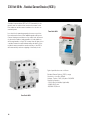
230 Volt 50 Hz - Residual Current Devices (RCD’s)
Two Pole RCD
Four Pole RCD
A residual current device (RCD, or R.C.D. henceforth) is the
generic term for a device that monitors the current in the
line conductor and the neutral conductor of a circuit in an
earthed system.
In a circuit that’s operating properly, the vector sum of the
live and neutral current values added together will be zero.
Current flowing to earth, due to a line earth fault, will return
via the earth conductor, and regardless of load conditions,
will be registered as a fault. This current flow will give rise to
a residual current that will be detected by the device. If the
residual current exceeds the rated sensitivity of the RCD, it
will automatically activate a tripping of the faulty circuit.
Typical specifications are as follows:
Residual Current Devices ( RCD’s ) range
Sensitivity - from 10 to 500mA
Voltage - 2 poles : 230V; 3/4 poles: 230/400V
Connection capacity
- 25A: 6/10 mm² (flexible/ rigid cable)
- 40,60A: 16/25 mm²
- 80,100A: 35/50 mm²

15
TB1
HTR2
J101
J50
J57
J25
J32
J52
J51
F6, T30A 480V
J47
1
2
3
4
W1
Balboa
BALBOA INSTRUMENTS, INC.
GS500Z
COPYRIGHT 2007
MADE IN U.S.A.
P/N 22015_B
Pb
IMPORTANT!
Remember, high voltage is still accessible in the house
breaker box even though you have turned off the spa breaker.
Keep in mind that a majority of R.C.D. tripping
problems can be attributed to incorrect wiring.
R.C.D. troubleshooting usually finds the problem.
RCD LINE-IN WIRING CHECK
UÊ V>ÌiÊÌiÊ«À«iÀÊVÀVÕÌÊLÀi>iÀÊ>`ÊÌÕÀÊÌÊvv°
UÊ ,iÛiÊÌiÊVÛiÀÊvÀÊÌiÊÕÃiÊLÀi>iÀÊLÝ°ÊiV
the main service amperage rating to the breaker box.
UÊ ÀÊÌiÊVÀVÕÌÊLÀi>iÀ]ÊV>ÌiÊÌiÊLÀÜÊ>`ÊÜÀiÊ>`Ê
the blue neutral wire.
UÊ ÀÊÌiÊ,°°°ÊiÕÌÀ>ÊL>À]ÊV>ÌiÊÌiÊLÕiÊ>`ÊiÕÌÀ>]Ê
and the green ground wire.
UÊ iÊÃÕÀiÊÌiÀiÊ>ÀiÊÊÌiÀÊ>««>ViÃÊÊÌiÊë>Ê
circuit. If there are, service must be re-wired to supply the
spa only.
UÊ >iÊÃÕÀiÊ>ÊÌÀiiÊÜÀiÃÊiÝÌÊÌiÊÕÃiÊLÀi>iÀÊLÝÊ
via conduit, routed to the R.C.D. breaker box. The brown
should be connected to the R.C.D. line-in. The blue load
neutral connects to the neutral in.
RCD LINE-OUT WIRING CHECK FOR 230 V
DEDICATED SYSTEM
The brown wire should connect to load out, the blue wire
from neutral out. All wires will exit the box via conduit
routed to the spa control system.
Once you have found all wiring correctly installed, begin
to check for proper voltage. If Correct Wiring is Verified,
check to see if the proper RCD is installed.
Check the label in the system box near TB1 to determine UÊ
the maximum amperage draw for the system.
Be sure the R.C.D. is rated for more amperage than the UÊ
system will draw.
For a 230 V dedicated system, a 2-pole or 4-pole R.C.D. UÊ
with no load neutral is acceptable.
For a detailed wiring checklist, please review the previ-UÊ
ous segment of this manual on proper R.C.D. wiring or
the R.C.D. manufacturer’s instructions.
If the wiring is correct and the R.C.D. will not reset, then UÊ
unplug the pump and try to reset the R.C.D.
If the R.C.D. trips again, then unplug the blower and UÊ
push the reset button. If the R.C.D. continues to trip,
then do the same procedure for the ozone generator.
If the R.C.D. stops tripping after you unplugged one UÊ
of the spa’s components, turn off the power to the
spa then plug in each component except the one that
tripped the R.C.D.
Power up the system. If the R.C.D. no longer trips, then UÊ
you have correctly identified the problem.
Repair or replace the component as instructed by the UÊ
spa manufacturer.
If you have unplugged all of the spa’s components and UÊ
the R.C.D. still doesn’t reset, then the problem is most
likely a ground fault in the heater.
Disconnect the heater, and test.UÊ
Wiring Check for RCD and Service Disconnect

16
Diagnosing M7 Topside Control Panels
PRELIMINARY PANEL CHECK
If the problem is not obvious, look on the topside control UÊ
panel for diagnostic messages.
If no messages are seen, run through all spa functions
and note any inconsistent operation.
Most error messages are stored in the fault log. To view UÊ
the fault log, the spa must be in test mode and the spa
light must be turned on.
Once you have determined that proper voltage is running
through the circuit board and transformer, continue to the
topside control panel. A panel that is not functioning properly
may include the following symptoms: low voltage such as
missing or scrambled segments, missing icons on the LCD,
non-functional LED’s, or nonfunctional buttons. If any of these
symptoms are present, perform the following:
Turn the power off and unplug the panel from the UÊ
circuit board.
Then, plug in your test panel and restore power. If every-UÊ
thing functions normally, replace the topside panel.
Disconnect ozone generator (if applicable).UÊ
If you still see symptoms of low voltage, such as a UÊ
sluggish, blank or partially blank panel, or if the display
or the LED’s do not function at all, turn the power off;
unplug the ozone generator (if equipped); then restore
power to the system. If the problem persists, turn off the
power and replace the circuit board.
PANEL DISPLAY MESSAGES
THE PANEL DISPLAYS:
, , or
At least one of the sensors has detected water temperatures
of 48ºC inside the heater. Or,
THE PANEL DISPLAYS:
, , or
One of the sensors has detected the temperature
of the water coming into the heater to be 43.5ºC,
and so the water in the spa is likely to be that hot.
These indicate that the spa has shut down due to an
overheat situation.
NOTE: Overheating may occur if the low-speed pump is set
to operate for extended periods of time, or if the incorrect
pump is installed. In rare cases (usually warmer climates), the
circulation pump may also cause overheating.
MOST PROBABLE OVERHEATING CAUSES.
INSPECT THESE FIRST
Check slice or ball valves. Make sure that they UÊ
are open.
Make sure the correct pump is installed.UÊ
Clean the filter/skimmer if there is any blockage.UÊ
Check heater element alignment.UÊ
Check for debris on the heater element.UÊ
In extremely hot weather, check for proper UÊ
cabinet ventilation.
Make sure the temperature sensor is fully inserted UÊ
into the sensor fitting on the heater.
Check for excessive filter duration.UÊ
Panel messages are a quick clue toward solving a variety of problems. Here are the most common messages and what
they mean.

17
NOTE: A common programming mistake is overlapping filter
times that may cause the spa to filter continuously.
Check the water level.UÊ
Check the water temperature with an accurate UÊ
thermometer. Remove the spa cover and allow the
water to cool to below 42°C. Adding cool water may be
necessary. Touch any button to reset the system. If the
water is still hotter than the set temperature, press the
blower button (if applicable) to cool the spa.
THE PANEL DISPLAYS:
, , , or
or
THE PANEL DISPLAYS:
, , , or
or
This indicates that the spa has shut down due to an open or
faulty sensor. If the problem recurs, test the sensor set. (See
Testing the Sensor Set.)
NOTE: In rare cases, rapid system overheat causes sensor
error messages. Be sure to rule out possible situations like no
flow or no water.
THE PANEL DISPLAYS:
, , or
This indicates that the sensors are out of balance.
If alternating with temperature, it may just be a temporary
condition. If flashing by itself, spa is shut down.
If the panel also displays “Service Req”, spa is shut down.
If the spa shuts down due to this error, one (or both) of the
sensors are probably reading several degrees off. If the
problem recurs, test the sensor set.
NOTE: All spa models are different in shape and size
and have different thermal characteristics; therefore,
Balboa Water Group cannot be held responsible
for freeze damage to the spa’s plumbing. Testing
is the responsibility of the spa manufacturer and
must be done to determine the best location for the
freeze sensor.
THE PANEL DISPLAYS:
, , or
This indicates that the auxiliary sensor detects a pos-
sible freeze condition. This is a normal spa function; no
further action is necessary.
When the auxiliary sensor reads around 4.4°C (40°F, actual
temperature dependent on specific auxiliary sensor used), the
system provides freeze protection. It automatically activates
all of the pumps and the blower to circulate water and warm
the plumbing.
NOTE: This auxiliary freeze protection functions at all times,
even when another fault condition has occurred and has
otherwise shut the spa down.
Any time the lower of the two temperature sensors
goes below 7°C (45°F), all pumps/blowers turn on. They
continue to run for 4 minutes after the temperature reaches
7°C or above. As soon as the temperature falls below 7°C
again, this process restarts. This “simplified” sensor freeze
protection functions at all times, even when another fault
condition (other than total sensor failure) has occurred and
has otherwise shut the spa down.
THE PANEL DISPLAYS:
, , or
This indicates that a substantial difference in tem-
perature between sensors has been detected during
heating.
This could indicate a flow problem. Check water level in spa.
Refill, if necessary. If the water level is okay, make sure the
pumps have been primed. On the fifth occurrence of the
above message the panel will display:

18
SOME TROUBLESHOOTING SCENARIOS
You find out the system is in “OHH”. This alone doesn't explain
a lot. What led up to the “OHH” is much more important.
See if the user has any additional information (for example,
how long before the “OHH” was the spa panel last checked,
and how hot was the water then). If the spa has cooled, see
whether the problem can happen again, this time watching
carefully to see if there are additional clues leading to the
“OHH” (for example, other messages that appear shortly
before the “OHH” happens).
You find out the system keeps showing “HFL”, or is now in
“LF”, or is shut down due to a "dry" fault. Put the spa in test
mode with the light on, so that you see the two sensor
temperatures. Are they normal (within .5°C/1°F) when not
heating? How far apart are they when heating? “HFL”
happens when they are 3°C/6°F apart (2°C/4°F on 120V
and other low-heater-wattage systems), see how quickly
that happens after heating starts. If it's getting close to that
right away, it's probably a consistent flow problem, but if it's
nowhere close to the “HFL”-causing temperature difference,
the flow problem may be intermittent or only occur in certain
specific situations.
, or
This indicates a persistent flow problem. The heater
is shut down while all other spa functions continue to run
normally. Power on the spa must be cycled before the heater
will function again.
THE PANEL DISPLAYS:
, , or
This indicates that there is not enough water in the
heater. Spa shuts down for 15 minutes.
This could indicate poor flow or air bubbles in the heater.
On the third consecutive occurrence of the above message
(without a successful heating cycle in between) the panel
will display
:
, , or
Spa is shut down and will not reset in 15 minutes. Press any
button to reset manually.
THE PANEL DISPLAYS:
, , or
This indicates that the temperature is completely
unknown because the pump has not yet run for 2 minutes
after Priming Mode was exited. This is only displayed for 2
minutes at power-up.
Diagnosing M7 Topside Control Panels (cont.)

19
Basic Control System Troubleshooting
LOW VOLTAGE
At Balboa, it’s been our experience that the majority of the
problems associated with electronic control systems are due
to low voltage.
BROWN OUTS
“Brown outs” can have an effect on the spa’s operation in
a variety of ways. The control panel may go blank, have
scrambled messages on the LCD, or only a few features
will function.
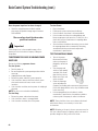
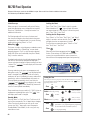
CHECKING THE SYSTEM POWER INPUT FUSE
Warning
These procedures are performed while the system is
powered up and running under peak loads. Be careful.
Systems that use 230V peripheral devices (below):
Measure between the brown TB1 terminal and F6 power UÊ
input fuse on the side farthest away from the circuit
board edge (opposite the F6 silk screen). You should see
230 volts.
If the system is equipped with the additional F6 power UÊ
input fuse, measure F6 in the same manner. You should
also see 230 volts.
If you determine that there is no voltage at one or both UÊ
locations, then the system power input fuse(s) need to
be replaced. Only use a fuse of the same type and amp
rating when you replace any of these fuses.
NOTE FOR ALL SYSTEMSUÊ In each situation, the most
likely reason for the system power input fuse to blow
is a pump problem. However, on occasion, a blower
problem may also cause this fuse to blow if a 10A
blower fuse is not built in.
(cont. next page)
If the system is getting the proper voltage
at TB1, but still doesn’t operate, then test for
a blown power input fuse.
Terminal Block 1
&
F6 Power Input Fuse
on a GS500Z Board
TB1
HTR2
J101
J50
J57
J25
J32
J52
J51
F6, T30A 480V
J47
1
2
3
4
W1
Balboa
BALBOA INSTRUMENTS, INC.
GS500Z
COPYRIGHT 2007
MADE IN U.S.A.
P/N 22015_B
Pb
TB1 Marking
on Board
F6
Power Input Fuse

20
Test the Blower
Plug in the blower.UÊ
Power up the system and activate the blower.UÊ
If the fuse blows, then there is a blower problem.UÊ
If the fuse does not blow, the combined pump and UÊ
blower amperage may be excessive. To verify this, first
check with your spa manufacturer for amperage draw
limits on each device.
Since the blower should now be running, you can check UÊ
the amperage draw with an ammeter by measuring
around the black blower wire and compare with
manufacturer’s specifications.
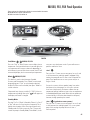
TEST THE AMPERAGE DRAW
Turn off the power, UÊ
disconnect the blower,
make sure the pump is
plugged in, and restore
power.
Start the pump and UÊ
switch to high speed (if
available), this should
draw the most current.
Make sure all jets and UÊ
valves are open.
Check the amperage UÊ
at the red pump wire.
Compare your reading with manufacturer specifications.
(If the other plug-in devices exist, they should be tested
in the same way.)
If the amperage draw for each device is within UÊ
manufacturer’s specifications, the problem could be a
nuisance spike in the pump, or water in the blower.
NOTE: These slow-blow fuses are not always discolored
when blown. Always test continuity of a fuse with
an ohmmeter.
NOTE: Miswiring of the spa is the most common reason for
this fuse to blow. However, a lightning strike in the area is a
possible, though less likely, cause of the failure.
Basic Control System Troubleshooting (cont.)
Once the power input fuse has been changed
Check the voltage between the black and red UÊ
wires again. Acceptable voltage range is between
216V and 264V.
These readings should be taken under
peak load conditions.
Important
If the voltage is not in the acceptable range, call an
electrician or the local electric company to diagnose
the problem.
TO DETERMINE THE CAUSE OF A BLOWN POWER
INPUT FUSE
Perform the following sequence of tests.
Test the System
Turn the power off.UÊ
Be sure to replace the system power input fuse with the UÊ
same type.
Unplug the blower and all pumps.UÊ
Restore the power and verify system operation.UÊ
If the fuse blows, then re-check the internal system UÊ
wires and connector for burns, cracks or cuts in
insulation.
If the fuse does not blow, turn the power off and plug in UÊ
the pump.
NOTE: Be sure to test each device individually.
Test the Pump
Restore the power and activate the pump.UÊ
If the fuse blows, there is a pump problem.UÊ
If the fuse does not blow, turn off the power.UÊ
Page is loading ...
Page is loading ...
Page is loading ...
Page is loading ...
Page is loading ...
Page is loading ...
Page is loading ...
Page is loading ...
Page is loading ...
Page is loading ...
Page is loading ...
Page is loading ...
Page is loading ...
Page is loading ...
Page is loading ...
Page is loading ...
Page is loading ...
Page is loading ...
Page is loading ...
Page is loading ...
Page is loading ...
Page is loading ...
Page is loading ...
Page is loading ...
Page is loading ...
Page is loading ...
Page is loading ...
Page is loading ...
-
 1
1
-
 2
2
-
 3
3
-
 4
4
-
 5
5
-
 6
6
-
 7
7
-
 8
8
-
 9
9
-
 10
10
-
 11
11
-
 12
12
-
 13
13
-
 14
14
-
 15
15
-
 16
16
-
 17
17
-
 18
18
-
 19
19
-
 20
20
-
 21
21
-
 22
22
-
 23
23
-
 24
24
-
 25
25
-
 26
26
-
 27
27
-
 28
28
-
 29
29
-
 30
30
-
 31
31
-
 32
32
-
 33
33
-
 34
34
-
 35
35
-
 36
36
-
 37
37
-
 38
38
-
 39
39
-
 40
40
-
 41
41
-
 42
42
-
 43
43
-
 44
44
-
 45
45
-
 46
46
-
 47
47
-
 48
48


Code Soft CS6200 Series User guide
- Type
- User guide
- This manual is also suitable for
Ask a question and I''ll find the answer in the document
Finding information in a document is now easier with AI
Other documents
-
Balboa ML200 Quick Reference Manual
-
Balboa Water Group 500SZ-Series Operating instructions
-
-
-
-
 Balboa Instruments ML551 User manual
-
-
-
 Cal Spas Portable Spa Owner's manual
-

