Page is loading ...

i
K9N2 SLI Platinum
Series
MS-7374 (v1.X) Mainboard
G52-73741X1

ii
Copyright Notice
The material in this document is the intellectual property of MICRO-STAR
INTERNATIONAL. We take every care in the preparation of this document, but no
guarantee is given as to the correctness of its contents. Our products are under
continual improvement and we reserve the right to make changes without notice.
Trademarks
All trademarks are the properties of their respective owners.
NVIDIA, the NVIDIA logo, DualNet, and nForce are registered trademarks or trade-
marks of NVIDIA Corporation in the United States and/or other countries.
AMD, Athlon™, Athlon™ XP, Thoroughbred™, and Duron™ are registered trade-
marks of AMD Corporation.
Intel
®
and Pentium
®
are registered trademarks of Intel Corporation.
PS/2 and OS
®
/2 are registered trademarks of International Business Machines
Corporation.
Windows
®
95/98/2000/NT/XP are registered trademarks of Microsoft Corporation.
Netware
®
is a registered trademark of Novell, Inc.
Award
®
is a registered trademark of Phoenix Technologies Ltd.
AMI
®
is a registered trademark of American Megatrends Inc.
Revision History
Revision Revision History Date
V1.0 First release for PCB 1.X April 2008
Technical Support
If a problem arises with your system and no solution can be obtained from the user’s
manual, please contact your place of purchase or local distributor. Alternatively,
please try the following help resources for further guidance.
Visit the MSI website for FAQ, technical guide, BIOS updates, driver updates,
and other information: http://global.msi.com.tw/index.php?
func=faqIndex
Contact our technical staff at: http://support.msi.com.tw/

iii
Safety Instructions
CAUTION: Danger of explosion if battery is incorrectly replaced.
Replace only with the same or equivalent type recommended by the
manufacturer.
1. Always read the safety instructions carefully.
2. Keep this User’s Manual for future reference.
3. Keep this equipment away from humidity.
4. Lay this equipment on a reliable flat surface before setting it up.
5. The openings on the enclosure are for air convection hence protects the equip-
ment from overheating. DO NOT COVER THE OPENINGS.
6. Make sure the voltage of the power source and adjust properly 110/220V be-
fore connecting the equipment to the power inlet.
7. Place the power cord such a way that people can not step on it. Do not place
anything over the power cord.
8. Always Unplug the Power Cord before inserting any add-on card or module.
9. All cautions and warnings on the equipment should be noted.
10. Never pour any liquid into the opening that could damage or cause electrical
shock.
11. If any of the following situations arises, get the equipment checked by a service
personnel:
† The power cord or plug is damaged.
† Liquid has penetrated into the equipment.
† The equipment has been exposed to moisture.
† The equipment has not work well or you can not get it work according to
User’s Manual.
† The equipment has dropped and damaged.
† The equipment has obvious sign of breakage.
12. DO NOT LEAVE THIS EQUIPMENT IN AN ENVIRONMENT UNCONDITIONED, STOR-
AGE TEMPERATURE ABOVE 60
0
C (140
0
F), IT MAY DAMAGE THE EQUIPMENT.

iv
FCC-B Radio Frequency Interference Statement
This equipment has been
tested and found to comply
with the limits for a Class B
digital device, pursuant to Part
15 of the FCC Rules. These limits are designed to provide reasonable protection
against harmful interference in a residential installation. This equipment generates,
uses and can radiate radio frequency energy and, if not installed and used in accor-
dance with the instructions, may cause harmful interference to radio communications.
However, there is no guarantee that interference will not occur in a particular
installation. If this equipment does cause harmful interference to radio or television
reception, which can be determined by turning the equipment off and on, the user is
encouraged to try to correct the interference by one or more of the measures listed
below.
† Reorient or relocate the receiving antenna.
† Increase the separation between the equipment and receiver.
† Connect the equipment into an outlet on a circuit different from that to
which the receiver is connected.
† Consult the dealer or an experienced radio/television technician for help.
Notice 1
The changes or modifications not expressly approved by the party responsible for
compliance could void the user’s authority to operate the equipment.
Notice 2
Shielded interface cables and A.C. power cord, if any, must be used in order to
comply with the emission limits.
VOIR LA NOTICE D ’INSTALLATION AVANT DE RACCORDER AU RESEAU.
Micro-Star International
MS-7374
This device complies with Part 15 of the FCC Rules. Operation is subject to the
following two conditions:
(1) this device may not cause harmful interference, and
(2) this device must accept any interference received, including interference that
may cause undesired operation.

v
WEEE (Waste Electrical and Electronic Equipment) Statement

vi

vii

viii
CONTENTS
Copyright Notice..............................................................................................................ii
Trademarks.......................................................................................................................ii
Revision History..............................................................................................................ii
Technical Support...........................................................................................................ii
Safety Instructions.........................................................................................................iii
FCC-B Radio Frequency Interference Statement........................................................iv
WEEE (Waste Electrical and Electronic Equipment) Statement....................................v
Chapter 1. Getting Started....................................................................................1-1
Mainboard Specifications...................................................................................1-2
Mainboard Layout................................................................................................1-4
Packing Checklist.................................................................................................1-5
Chapter 2. Hardware Setup..................................................................................2-1
Quick Components Guide....................................................................................2-2
CPU (Central Processing Unit)............................................................................2-3
Memory.................................................................................................................2-6
Power Supply......................................................................................................2-8
Back Panel..........................................................................................................2-10
Connectors........................................................................................................2-12
Button.................................................................................................................2-19
Slots....................................................................................................................2-20
LED Status Indicators........................................................................................2-25
Chapter 3 BIOS Setup.............................................................................................3-1
Entering Setup.....................................................................................................3-2
The Main Menu.....................................................................................................3-4
Standard CMOS Features...................................................................................3-6
Advanced BIOS Features...................................................................................3-8
Integrated Peripherals........................................................................................3-11
Power Management Setup...............................................................................3-13
H/W Monitor........................................................................................................3-16
BIOS Setting Password.....................................................................................3-17
Cell Menu............................................................................................................3-18
USER SETTINGS................................................................................................3-23
Load Fail-Safe/ Optimized Defaults.................................................................3-24
Appendix A Realtek ALC888 Audio....................................................................A-1
Installing the Realtek HD Audio Driver................................................................A-2

ix
Software Configuration......................................................................................A-4
Hardware Setup................................................................................................A-19
Appendix B NVIDIA RAID.........................................................................................B-1
Introduction..........................................................................................................B-2
RAID Configuraiton..............................................................................................B-3
Installing Driver....................................................................................................B-7
NVIDIA RAID Utility Installation.............................................................................B-8
Using the NVMediaShield Software.................................................................B-11
Appendix C JMicron RAID Introduction............................................................C-1
Introduction..........................................................................................................C-2
JMicron RAID BIOS Utility....................................................................................C-3
Installing Driver..................................................................................................C-11
JMicron RAID Configurer...................................................................................C-13
Appendix D Dual Core Center..............................................................................D-1
Activating Dual Core Center...............................................................................D-2
Main......................................................................................................................D-3
DOT(Dyanmic OverClocking)..............................................................................D-5
Clock.....................................................................................................................D-6
Voltage.................................................................................................................D-7
FAN Speed...........................................................................................................D-8
Temperature.........................................................................................................D-9
User Profile........................................................................................................D-10

1-1
Getting Started
Getting Started
Chapter 1
Thank you for choosing the K9N2 SLI Platinum Series
(MS-7374 v1.X) ATX mainboard. The K9N2 SLI Platinum
Series mainboards are based on NVIDIA
®
nForce750a
SLI single chipset for optimal system efficiency. De-
signed to fit the advanced AMD
®
Phenom/Athlon/
Sempron series in Socket AM2/ AM2+, the K9N2 SLI
Platinum Series deliver a high performance and profes-
sional desktop platform solution.

MS-7374 Mainboard
1-2
Mainboard Specifications
Processor Support
- AMD
®
Phenom/ Athlon/ Sempron series processors in AM2/ AM2+
package
- Supports 4 pin CPU Fan Pin-Header with Fan Speed Control
(For the latest information about CPU, please visit
http://global.msi.com.tw/index.php?func=cpuform)
Supported FSB
- AM2 CPU supports Hyper Transport 1.0
- AM2+ CPU supports Hyper Transport 3.0
Chipset
- NVIDIA
®
nForce 750a SLI (MCP 72P) chipset
Memory Support
- DDR2 1066 (for AM2+ CPU only)/ 800/ 667 DRAM (240pin/ 1.8V)
- 4 DDR2 DIMMs (8GB Max)
(For more information on compatible components, please visit
http://global.msi.com.tw/index.php?func=testreport)
LAN
- Supports 10/100/1000 Fast Ethernet by Realtek 8211BL
1394 (optional)
- Transfer rate is up to 400Mbps
- Controlled by VIA VT6308P (optional)
Audio
- Chip integrated by Realtek
®
ALC888
- Flexible 8-channel audio with jack sensing
- Compliant with Azalia 1.0 spec
IDE
- 2 IDE ports (one by nForce 750a SLI, one by JMB363)
- Supports Ultra DMA 66/100/133 mode
- Supports PIO, Bus Master operation mode
SATA
- 6 SATAII ports by nForce 750a SLI
- 2 ESATA (External-SATA) ports (back panel) by JMB363
- Supports storage and data transfers at up to 3 Gb/s
RAID
- SATA1~6 support RAID 0/ 1/ 0+1/ 5 or JBOD mode
- 2 ESATA (External-SATA) ports support RAID 0/ 1 mode
Floppy
- 1 floppy port
- Supports 1 FDD with 360KB, 720KB, 1.2MB, 1.44MB and 2.88MB

1-3
Getting Started
Connectors
Back panel
- 1 PS/2 mouse port
- 1 PS/2 keyboard port
- 1 1394 port (optional)
- 1 Optical SPDIF-out jack
- 1 DVI-D port
- 1 LAN jack
- 4 USB 2.0 ports
- 2 ESATA ports
- 6 flexible audio jacks
On-Board Pinheaders
- 3 USB 2.0 pinheaders
- 1 1394 pinheader (optional)
- 1 Front Panel Audio pinheader
- 1 CD-in pinheader
- 1 Serial port pinheader
- 1 TPM Module pinheader (optional)
- 1 SPDIF-out pinheader
- 1 Chassis Intrusion pinheader
TPM (optional)
- Supports TPM
Slots
- 2 PCI Express x16 slots compatible with PCIE 2.0 specification,
supports SLI mode
a. the mazarine PCIE x16 (PCI_E1) slot supports up to PCIE 2.0
x16 speed
b. the blue PCIE x16 (PCI_E3) slot is a special design that
supports up to PCIE 2.0 x8 speed
c. if you intend to use both PCIE x16 slots, please use them with
graphics cards in SLI mode and these two PCIE x16 lanes will
auto arrange from x16/ x0 to x8/ x8
- 1 PCI Express x 1 slot
- 2 PCI slots
Form Factor
- ATX (30.5cm X 24.4 cm)
Mounting
- 9 mounting holes

MS-7374 Mainboard
1-4
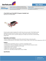
K9N2 SLI Platinum Series (MS-7374 v1.X)
ATX Mainboard
Mainboard Layout
PCI 2
PCI 1
BATT
+
I
D
E
1
A
T
X
1
Socket AM2
DIM
M
1
DIM
M
2
DIM
M
3
DIM
M
4
JCOM1
JAUD1
JCD1
SPDOUT1
FDD1
J1394_1
JFP1
RESET
PWR_BTN
CLEAR CMOS
JFP2
IDE2
JUSB2 JUSB3
JUSB1
JTPM1
SATA5
SATA1_3
SATA6
SYSFAN3
CPUFAN1
JPW2
JPW3
SYSFAN1
SYSFAN2
SATA2_4
SYSFAN4
PCI _E3
PCI _E2
PCI _E1
Top: LAN Jack
Bottom: USB ports
USB ports
T:Line-In
M:Line-Out
B:Mic
T:RS-Out
M:CS-Out
B:SS-Out
Top : mouse
Bottom:keyboard
eSATA ports
Top: DVI
Bottom:
1394 port (optional)
Optical SPDIF-out
ports
JMicron
JMB363
Audio
Coedc
JCI1
I/O
Chip
LAN
Chip
NForce
750a SLI
VIA
VT6308P
(optional)
(Optional)
(Optional)

1-5
Getting Started
Packing Checklist
Power Cable
User’s Guide
MSI motherboard
MSI Driver/Utility CD
* The pictures are for reference only and may vary from the packing contents of the
product you purchased.
Floppy Cable
IDE Cable
SLI Video Link Card
Back IO Shield
1394 Bracket (Optional)
SATA Cable
external SATA Cable
(Optional)

2-1
Hardware Setup
Hardware Setup
Chapter 2
This chapter provides you with the information about
hardware setup procedures. While doing the installation,
be careful in holding the components and follow the
installation procedures. For some components, if you
install in the wrong orientation, the components will not
work properly.
Use a grounded wrist strap before handling computer
components. Static electricity may damage the
components.

2-2
MS-7374 Mainboard
DDR2 DIMMs,
p.2-6
JFP2, p.2-18
Back Panel
I/O, p.2-10
IDE1, p.2-12
ATX1, p.2-8
PCI Slots,
p.2-24
JUSB1~3, p.2-16
SATA, p.2-13
SYSFAN2, p.2-14
CPUFAN1, p.2-14
PCI Express
slots, p.2-20
CPU, p.2-3
J1394_1,
p.2-17
Quick Components Guide
JAUD1,
p.2-15
CLEAR CMOS,
p.2-19
SYSFAN3,
p.2-14
JFP1, p.2-18
JCD1,
p.2-15
JCI1, p.2-15
FDD1,
p.2-13
SPDOUT1,
p.2-14
JPW3, p.2-8
JTPM1, p.2-17
JCOM1,
p.2-16
RESET, p.2-19
PWR_BTN,
p.2-19
SYSFAN4,
p.2-14
IDE2,
p.2-12
SYSFAN1,
p.2-14
JPW2, p.2-8

2-3
Hardware Setup
The mainboard supports AMD
®
Phenom/ Athlon/ Sempron processors in Socket
AM2/ AM2+. The Socket AM2/ AM2+ offer a easy CPU installation. When you are
installing the CPU, make sure the CPU has a heat sink and a cooling fan
attached on the top to prevent overheating. If you do not have the heat sink and
cooling fan, contact your dealer to purchase and install them before turning on the
computer.
For the latest information about CPU, please visit http://global.msi.com.tw/index.
php?func=cpuform
CPU (Central Processing Unit)
Important
Overheating
Overheating will seriously damage the CPU and system. Always make sure
the cooling fan can work properly to protect the CPU from overheating. Make
sure that you apply an even layer of thermal paste (or thermal tape) between
the CPU and the heatsink to enhance heat dissipation.
Replacing the CPU
While replacing the CPU, always turn off the ATX power supply or unplug the
power supply’s power cord from the grounded outlet first to ensure the safety
of CPU.
Overclocking
This mainboard is designed to support overclocking. However, please make
sure your components are able to tolerate such abnormal setting, while
doing overclocking. Any attempt to operate beyond product specifications is
not recommended. We do not guarantee the damages or risks caused
by inadequate operation or beyond product specifications.

2-4
MS-7374 Mainboard
CPU Installation Procedures for Socket AM2/ AM2+
1.Please turn off the power and
unplug the power cord before
installing the CPU.
2.Pull the lever sideways away
from the socket. Make sure to
raise the lever up to a 90-de-
gree angle.
3.Look for the gold arrow on the
CPU. The gold arrow should point
as shown in the picture. The CPU
can only fit in the correct
orientation. Lower the CPU down
onto the socket.
4.If the CPU is correctly installed,
the pins should be completely
embedded into the socket and
can not be seen. Please note
that any violation of the correct
installation procedures may
cause permanent damages to
your mainboard.
5. Press the CPU down firmly into
the socket and close the lever.
As the CPU is likely to move while
the lever is being closed, al-
ways close the lever with your
fingers pressing tightly on top of
the CPU to make sure the CPU is
properly and completely embed-
ded into the socket.
Open the lever
90 degree
Sliding
the plate
Gold arrow
Gold arrow
Gold arrow
Correct CPU
placement
O
Incorrect CPU
placement
Press down
the CPU
Close
the lever

2-5
Hardware Setup
Installing CPU Cooler Set
When you are installing the CPU, make sure the CPU has a heat sink and a
cooling fan attached on the top to prevent overheating. If you do not have the
heat sink and cooling fan, contact your dealer to purchase and install them before
turning on the computer.
2. Then press down the other end of
the clip to fasten the cooling set on
the top of the retention mechanism.
Locate the Fix Lever and lift it up.
1.Position the cooling set onto the re-
tention mechanism.
Hook one end of the clip to hook
first.
3.Fasten down the lever.
4.Attach the CPU fan cable to the CPU
fan connector on the mainboard.
Fixed Lever
Important
1. Read the CPU status in BIOS (Chapter 3).
2. Mainboard photos shown in this section are for demonstration of the CPU/
cooler installation only. The appearance of your mainboard may vary depend-
ing on the model you purchase.

2-6
MS-7374 Mainboard
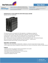
Memory
These DIMM slots are used for installing memory modules.
For more information on compatible components, please visit http://global.msi.com.
tw/index.php?func=testreport
1
DIMM1
DIMM2
DIMM3
DIMM4
2
DIMM1
DIMM2
DIMM3
DIMM4
Dual-Channel Memory Population Rules
In Dual-Channel mode, the memory modules can transmit and receive data with two
data bus lines simultaneously. Enabling Dual-Channel mode can enhance the system
performance. The following illustrations explain the population rules for Dual-Channel
mode.
Empty
Installed
Important
-DDR2 memory modules are not interchangeable with DDR and the DDR2
standard is not backwards compatible. You should always install DDR2
memory modules in the DDR2 DIMM slots.
-In Dual-Channel mode, make sure that you install memory modules of the
same type and density in different channel DIMM slots.
-To enable successful system boot-up, always insert the memory modules
into the DIMM1 first.
- Due to the chipset resource deployment, the system density will only be
detected up to 7+GB (not full 8GB) when each DIMM is installed with a 2GB
memory module.
DDR2
240-pin, 1.8V
64x2=128 pin56x2=112 pin
/