Page is loading ...

Vacuum spray degassing 28.08.2019 -
Rev. B
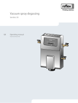
Servitec S
GB
Operating manual
Original operating manual


Contents
Vacuum spray degassing — 01.04.2021
English — 3
Contents
1 Information concerning the operating
manual ................................................... 4
2 Liability and warranty ........................... 4
3 Safety ..................................................... 5
3.1 Explanation of symbols ........................ 5
3.2 Personnel requirements ...................... 5
3.3 Personal protective equipment ............ 5
3.4 Intended use ........................................ 5
3.5 Impermissible operating conditions ..... 6
3.6 Residual risks ...................................... 6
4 Description of the device ..................... 7
4.1 Overview ............................................. 7
4.2 Identification ........................................ 7
4.3 Function ............................................... 8
4.4 Scope of delivery ................................. 9
4.5 Optional equipment and accessories ..10
5 Technical data ..................................... 10
5.1 Electrical system.................................10
5.2 Dimensions and connections ..............11
5.3 Operation ............................................11
6 Installation ........................................... 11
6.1 Incoming inspection ............................12
6.2 Preparatory work ................................12
6.3 Execution ............................................13
6.3.1 Fitting the add-on components
...........................................13
6.3.2 Wall mounting ....................14
6.3.3 Degassing line to the system
...........................................14
6.4 Switching and make-up variants .........15
6.4.1 Pressure-dependent
"Magcontrol" make-up mode16
6.4.2 Level dependent "Levelcontrol"
make-up mode ...................16
6.5 Electrical connection ...........................17
6.5.1 Terminal diagram ...............17
6.6 Installation and commissioning certificate
........................................................... 18
7 Commissioning ................................... 19
7.1 Requirements for initial commissioning19
7.2 Setting the minimum operating pressure
for Magcontrol .................................... 19
7.3 Filling the device with water ............... 20
7.4 Starting Automatic mode .................... 20
8 Operation ............................................. 21
8.1 Operating modes ............................... 21
8.1.1 Automatic mode................. 21
8.1.2 Stop mode ......................... 21
8.1.3 Restarting .......................... 21
9 Controller ............................................. 21
9.1 Reflex Control Smart .......................... 21
9.2 Operator panel ................................... 22
9.3 Manual make-up ................................ 23
9.4 Messages........................................... 23
9.5 Reset ................................................. 25
10 Maintenance ........................................ 25
10.1 Maintenance schedule ....................... 26
10.1.1 Cleaning the dirt trap ......... 26
11 Removal ............................................... 26
12 Disposal ............................................... 28
13 Appendix .............................................. 28
13.1 Reflex Customer Service ................... 28
13.2 Warranty ............................................ 28
13.3 Conformity and standards .................. 29
English
Vacuum spray degassing
01.04.2021

Information concerning the operating manual
4 — English
Vacuum spray degassing — 01.04.2021
See chapter "Overview" on page 7.
1 Information concerning the operating manual
This operating manual is an important aid for ensuring the safe and reliable functioning of the device.
Reflex Winkelmann GmbH accepts no liability for any damage resulting from failure to observe the information in this operating
manual. In addition to the requirements set out in this operating manual, national statutory regulations and provisions in the country
of installation must also be complied with (concerning accident prevention, environment protection, safe and professional work
practices, etc.).
Note!
Every person installing this equipment or performing any other work at the equipment is required to carefully read
this operating manual prior to commencing work and to comply with its instructions. The manual is to be provided to
the device operator and must be stored near the device for access at any time.
2 Liability and warranty
The device has been built according to the state of the art and recognised safety rules. Nevertheless, its use can pose a risk to life
and limb of personnel or third persons as well as cause damage to the system or other property.
It is not permitted to make any modifications at the device, such as to the hydraulic system or the circuitry.
The manufacturer shall not be liable nor shall any warranty be honoured if the cause of any claim results from one or more of the
following causes:
• Improper use of the device.
• Unprofessional commissioning, operation, service, maintenance, repair or installation of the device.
• Failure to observe the safety information in this operating manual.
• Operation of the device with defective or improperly installed safety/protective equipment.
• Opening the housing of the electrical controller.
• Failure to perform maintenance and inspection work according to schedule.
• Use of unapproved spare parts or accessories.
Prerequisite for any warranty claims is the professional installation and commissioning of the device.
Note!
Arrange for specialist personnel to carry out commissioning and annual maintenance.

Safety
Vacuum spray degassing — 01.04.2021
English — 5
3 Safety
3.1 Explanation of symbols
The following symbols and signal words are used in this operating manual.
DANGER
Danger of death and/or serious damage to health
The sign, in combination with the signal word 'Danger', indicates imminent danger; failure to
observe the safety information will result in death or severe (irreversible) injuries.
WARNING
Serious damage to health
The sign, in combination with the signal word 'Warning', indicates imminent danger; failure to
observe the safety information can result in death or severe (irreversible) injuries.
CAUTION
Damage to health
The sign, in combination with the signal word 'Caution', indicates danger; failure to observe the
safety information can result in minor (reversible) injuries.
ATTENTION
Damage to property
The sign, in combination with the signal word 'Attention', indicates a situation where damage to the
product itself or objects within its vicinity can occur.
Note!
This symbol, in combination with the signal word 'Note', indicates useful tips and recommendations
for efficient handling of the product.
3.2 Personnel requirements
Installation and operation tasks are to be carried out by specialist personnel or specially trained personnel only.
The electric connections and the wiring of the device must be executed by a trained electrician in accordance with all applicable
national and local regulations.
3.3 Personal protective equipment
Use the prescribed personal protective equipment as required (e.g. ear protection, eye protection, safety shoes, helmet, protective
clothing, protective gloves) when working at the system in which the device is installed.
Information on personal protective equipment requirements is set out in the relevant national regulations of the respective country of
operation.
3.4 Intended use
The device is used in plant systems for stationary heating and cooling circuits. The devices may be used only in systems that are
sealed against corrosion and with the following water types:
• Non-corrosive.
• Chemically non-aggressive.
• Non-toxic.
Minimise the entry of atmospheric oxygen throughout the plant system and into the make-up water.

Safety
6 — English
Vacuum spray degassing — 01.04.2021
Note!
Ensure the quality of the make-up water as specified by national regulations.
• For example, VDI 2035 or SIA 384-1.
Note!
• To ensure fault-free operation of the system over the long-term, glycols whose inhibitors prevent corrosion
phenomena must always be used for systems operating with water/glycol mixtures. It must also be ensured
that no foam is formed due to the substances in the water. Otherwise this could endanger the entire function
of the vacuum spray tube degassing as this can lead to sedimentation in the vent pipe and therefore leaks.
• The specifications of the respective manufacturer are always decisive for the specific properties and mixing
ratio of the water/glycol mixtures.
• Types of glycol must not be mixed and the concentration is generally to be checked every year (see
manufacturer information).
3.5 Impermissible operating conditions
The device is not suitable for the following applications:
• Outdoor operation.
• For use with mineral oils.
• For use with flammable media.
• For use with distilled water.
Note!
It is not permitted to make any modifications to the hydraulic system or the circuitry.
3.6 Residual risks
The device has been manufactured using state-of-the-art technology. Despite this, residual risks cannot be excluded.
WARNING
Risk of fire due to open ignition sources
The device housing is made of combustible material and is heat-sensitive.
• Avoid heat and ignition sources (flames or sparks).
CAUTION
Risk of burns on hot surfaces
Hot surfaces in heating systems can cause burns to the skin.
• Wear protective gloves.
• Please place appropriate warning signs in the vicinity of the device.
CAUTION
Risk of injury due to pressurised liquid
If installation, removal or maintenance work is not carried out correctly, there is a risk of burns and other injuries at the
connection points, if pressurised hot water or hot steam suddenly escapes.
• Ensure proper installation, removal or maintenance work.
• Ensure that the system is de-pressurised before performing installation, removal or maintenance work at the connection
points.
CAUTION
Risk of injury when upon coming into contact with glycol containing water
Contact with glycol containing water in plant systems for cooling circuits can result in irritation of the skin and eyes.
• Use personal protective equipment (safety clothing, gloves and goggles, for example).

Vacuum spray degassing — 01.04.2021
English — 7
CAUTION
Risk of injury due to heavy device weight
The device weight may cause physical injury or accidents.
• If necessary, work with a second person during assembly or disassembly.
ATTENTION
Device damage during transport
If the device is not transported correctly, it may be damaged.
• Use suitable covers to protect the connections against damage.
4 Description of the device
The Servitec is a degassing and make-up station. Its main areas of application are heating and cooling circuits and systems in
which malfunctions due to dissolved or free gases are to be prevented. The Servitec provides the following safety features:
• No direct intake of air due to control of pressurisation with automatic make-up.
• No circulation issues caused by free bubbles in the circuit water.
• Reduced corrosion damage due to oxygen removal from fill and make-up water.
4.1 Overview
The general view is located at the start of the operating manual.
1
Connection, WC make-up line
9
Motorized ball valve system-side
2
Controller
10
Pump
3
Gas-rich water inlet / System side DC
11
Spray tube
4
air vent
12
Pressure sensor
5
Check valve at the air vent
13
Motorized ball valve make-up side
6
Nameplate
WC
Make-up connection
7
Dirt trap
DC
Degassing connection
• Degassed water outlet
• Gas-rich water inlet
8
Degassed water outlet / System side DC
4.2 Identification
The nameplate provides information about the manufacturer, the year of manufacture, the manufacturing number and the technical
data.

Description of the device
8 — English
Vacuum spray degassing — 01.04.2021
4.3 Function
The device is suited for the degassing of water from the plant and make-up water. It removes up to 90 % of the dissolved gases
from the water. The degassing operation uses timer-controlled cycles. A cycle comprises the following phases:
1. Pump down to create a
vacuum
2. Injection
3. Discharge
4. Off time
< 1.8 …-0.8 bar
-0.8 bar
-0.8 bar… 1.8 bar
1.8 bar
Gas-rich water is sprayed into
the spray tube. The pump
draws more water from the
spray tube than can flow
through the nozzle.
Partial flows of the system or
make-up water are finely
atomised in the spray tube.
The large surface are of the
atomised water and the large
gas saturation difference
relative to that in the vacuum
result in degassing of the
water. The degassed water is
returned to the system via the
vacuum pump.
The pump shuts down. The
degassing process continues
running and the water level in
the vacuum spray tube
increases. The gases
separated from the water are
exhausted via the degassing
valve.
The device remains idling
until the next cycle is started.
Cooling water system ≤ 30 °C, System pressure 1.8 bar, DC system degassing in operation, WC make-up degassing closed.
Degassing
The entire degassing process is hydraulically regulated using the integrated pressure sensor and the device controller. The
operating conditions are monitored and can be called up and displayed from the device controller via a smartphone loaded with the
Reflex Control Smart app.
• Continuous degassing: (Suitable after commissioning or after repairs)
For continued degassing over several hours or days in a sequence of degassing cycles without idling periods.
• Interval degassing: (suitable for continuous operation)
Interval degassing comprises a limited number of degassing cycles. There is an idling time between the intervals.
• Make-up degassing:
In Magcontrol and Levelcontrol mode, make-up degassing is automatically activated upon every make-up request during
continuous or interval degassing. The make-up volume is monitored via the make-up time and the make-up cycles.
Make-up variants
There are two make-up variants for the device. These are selected in the controller and set for the device:
• Magcontrol (for systems with diaphragm expansion vessels):
Using the integrated "PIS" pressure sensor, the system registers and monitors the pressure in the heating or cooling system.
Make-up degassing is activated as soon as the pressure drops below the calculated filling pressure.
• Levelcontrol (for systems with pressurisation units):
The pressurisation unit uses the "LIS" pressure pick-up to determine the water level in the expansion vessel. The make-up
function is triggered by a 230 V signal.
If none of the above described make-up variants is selected, the following selection should be made via the Reflex Control Smart
app:
• "None": Automatic make-up is deactivated. A pressure-independent system degassing is taking place. Automatic system
pressure monitoring must be reliably externally provided.

Description of the device
Vacuum spray degassing — 01.04.2021
English — 9
Note!
For pipe lengths greater than 8 m we recommend selecting the next largest nominal diameter DN 20. Max. pipe
length 25 m.
1
“WC” make-up line nominal diameter DN 15
6
“DC” degassing line (degassed water to the facility
system), nominal diameter DN 15; DN 20
(8 m-25 m)
2
Optional accessories
7
“DC” degassing line (gas-rich water from the
facility system), nominal diameter DN 15; DN 20
(8 m-25 m)
3
Device
8
Device controller
4
Pump "PU"
9
Degassing valve "DV"
5
"PIS" pressure transducer from the device
10
230 volt signal - external make-up request from a
pressurisation unit
Note!
Ensure the correct connection of the device to the facility system.
– For the Levelcontrol make-up variant in particular, the 230 V supply cable for the external make-up request of
a pressurisation unit must be connected to the device.
– As supplied, automatic make-up is deactivated. A manual make-up via the make-up button on the device can
be performed, see chapter 9.3 "Manual make-up" on page 23 . In operation via the Reflex Control Smart app,
this is indicated and selected as “None” under the make-up variants selection.
4.4 Scope of delivery
The scope of delivery is described in the shipping document for the initial shipment and the content is shown on the packaging.
Immediately after receipt of the goods, please check the shipment for completeness and damage. Please notify us immediately of
any transport damage.
Basic degassing equipment:
• Device
• 3 ball valves for degassing and makeup connections
• Operating manual

Technical data
10 — English
Vacuum spray degassing — 01.04.2021
4.5 Optional equipment and accessories
The following optional equipment and accessories are available for this device:
Fillset
– For make-up with water.
Fillset with integrated backflow preventer, water meter, dirt trap, and locking mechanisms
for the "WC" make-up line.
Fillset Impuls with contact water
meter FQIRA+
– For make-up with water.
If the Fillset Impulse with FQIRA+ contact water meter is installed in the make-up line,
you can regulate the entire make-up quantity and the soft water capacity of Fillsoft
softening systems. The operational reliability of the device is assured and prevents
automatic make-up during major water loss or small leaks.
RS-485 interface
This interface is used to retrieve all controller data and to enable the communication with
control centres or other devices.
The following interfaces can be operated via the RS-485 port:
• Modbus RTU (integrated)
The list of transmitted data can be found in the Reflex Control Smart app.
Other modules upon request
Fillsoft
– For softening the make-up
water from the potable water
supply system.
Fillsoft is installed between Fillset and the device. The device controller evaluates the
make-up quantities and signals the required replacement of the softening cartridges.
Reflexomat
– For systems with
pressurisation units.
Make-up is executed depending on the water level measured with the "LIS" level sensor
of the Reflexomat in the expansion vessel of the pressurisation unit. If there is a make-up
requirement, the Reflexomat activates the Servitec make-up function via a 230V signal.
Note!
Separate installation, operation, and maintenance instructions are supplied with the accessories and optional
equipment.
5 Technical data
Note!
The following values apply for all systems:
– Permissible operating temperature:
– Permissible make-up water operating temperature:
– Permissible ambient temperature:
– Permissible operating gauge pressure:
– Maximum inlet pressure for make-up:
– Maximum make-up capacity:
– Separation level, dissolved gases:
– Separation level, free gases:
– Degree of protection:
70° C
0 °C – 30 °C
0 °C – 35 °C
8 bar
6 bar
≤ 0.08 m³/h
≤ 90 %
100 %
IP 42
5.1 Electrical system
Type
Power output
(kW)
Power supply
(V / Hz)
Fusing
(A)
Number of RS-
485 interfaces
Noise level
(dB)*
Servitec S
0.2
230 / 50
8
1 piece
54
* the value corresponds to the pump’s sound emission value under laboratory conditions.

Installation
Vacuum spray degassing — 01.04.2021
English — 11
5.2 Dimensions and connections
Type
Weight
(kg)
Height
(mm)
Width
(mm)
Depth
(mm)
Degassing
device
connection
Degassing
system
connection
Make-up
connection
Servitec S
12.4
572
340
211
Internal
thread ½ "
Internal
thread ½ "
Internal
thread ½ "
5.3 Operation
Type
System volume
(100% water)
(m³)
System volume
(50% water 50%
glycol)
(m³)
Working
pressure
(bar)
Permissible
operating gauge
pressure
(bar)
Operating
temperature
(°C)
Servitec S
6
4
0.5 – 4.5
8
>0 – 70
Standard values for the maximum "Va" system
volume to be degassed under extreme conditions
during commissioning at a nitrogen reduction
from 18 mg/l to 10 mg/l.
1 Continuous degassing "t" [h]
2. System volume "Va" [m3]
6 Installation
DANGER
Risk of serious injury or death due to electric shock.
If live parts are touched, there is risk of life-threatening injuries.
• Ensure that the system is voltage-free before installing the device.
• Ensure that the system is secured and cannot be reactivated by other persons.
• Ensure that installation work for the electric connection of the device is carried out by an electrician, and in compliance
with electrical engineering regulations.
CAUTION
Risk of injury due to pressurised liquid
If installation, removal or maintenance work is not carried out correctly, there is a risk of burns and other injuries at the
connection points, if pressurised hot water or hot steam suddenly escapes.
• Ensure proper installation, removal or maintenance work.
• Ensure that the system is de-pressurised before performing installation, removal or maintenance work at the connection
points.

Installation
12 — English
Vacuum spray degassing — 01.04.2021
CAUTION
Risk of burns on hot surfaces
Hot surfaces in heating systems can cause burns to the skin.
• Wear protective gloves.
• Please place appropriate warning signs in the vicinity of the device.
CAUTION
Risk of injury due to falls or bumps
Bruising from falls or bumps on system components during installation.
• Wear personal protective equipment (helmet, protective clothing, gloves, safety boots).
Note!
Confirm that installation and start-up have been carried out correctly using the installation and commissioning
certificate. This action is a prerequisite for the making of warranty claims.
– Arrange for specialist personnel to carry out commissioning and annual maintenance.
6.1 Incoming inspection
Prior to shipping, this device was carefully inspected and packed. Damages during transport cannot be excluded.
Proceed as follows:
1. Upon receipt of the goods, check the shipment for
• completeness and
• possible transport damage.
2. Document any damage.
3. Contact the forwarding agent to register your complaint.
6.2 Preparatory work
Condition of the delivered device:
• Check all screw connections of the device for tight seating. Tighten the screws as necessary.
Preparing the connection of the device to the facility system:
• Barrier-free access to the facility system.
• Frost-free, well-ventilated room. Room temperature > 0 - 35 °C.
• Drain for drain water.
• Filling connection: DN 15 according to DIN EN 1717.
• Electric connection: 230 V~, 50 Hz, 8 A with upstream RCD (tripping current: 0.03 A).
Note!
Shut-off valves must be used at the connection point to the pipe network.
Note!
The connection to the existing pipe network must be made via a flexible hose connection (especially in buildings with
high noise abatement requirements).
Note!
The wall mounting must be implemented in a sound-decoupling manner (especially in buildings with high noise
abatement requirements).

Installation
Vacuum spray degassing — 01.04.2021
English — 13
6.3 Execution
CAUTION
Risk of injury due to tipping over of the device
Risk of bruising or crushing caused by tipping over of the device.
• Ensure sufficient stability of the device.
• Weigh down the bearing surface of the device's transport unit with suitable means.
Note!
The screw connections at the device may loosen when the device is moved to another location.
• Before using the device check the screw connections for proper seating and sealing
Note!
Avoid leaks at the connections.
• When connecting the device to the plant system, ensure that the connections for degassing and make-up are
not twisted.
Proceed as follows:
• Connect the device on the return side of the facility system.
– Ensure that the device is operated within the permissible pressure and temperature ranges.
• In the case of a facility system with return flow admixture or a hydraulic switching point, connect the device upstream of the
switching point.
– In doing so, you guarantee water degassing in the "V" main volume flow at temperatures ≤ 70 °C.
CAUTION – damage due to improper connection! Bear in mind that the device may be subject to additional stresses through the
connection of piping or hose connections to the facility system. Ensure that all connections to the facility system are free from
stresses. If necessary, provide support structures for the pipes.
CAUTION – Property damage caused by leaks! Leaks in the connection pipes to the device can cause material damage to the
facility system. Use only connection pipes with adequate resistance against the facility system temperature.
The device is pre-wired and must be adapted to match the local facility system conditions.
Proceed as follows:
1. Complete the water side connections from the device to the facility system.
2. Complete the electric connection as shown in the terminal plan, see chapter 6.5 "Electrical connection" on page 17 .
Note!
When connecting, ensure the valves and supply element options of the connecting pipes can be operated.
6.3.1 Fitting the add-on components
Note!
In this respect, see the illustrations on the attached supplementary sheet.
Install the ball valves at the device.
1. Attach the ball valve (green handle) for the "WC" make-
up connection on the device.
– If no make-up line is connected, close the "WC"
connection with an externally threaded ½ " blind
plug.
2. For the system-side connection, fit the ball valve with
the “ST” dirt trap (blue handle) at the “DC” input on the
device.
3. For the system-side connection, fit the ball valve (red
handle) at the “DC” output on the device.

Installation
14 — English
Vacuum spray degassing — 01.04.2021
6.3.2 Wall mounting
Use the holes provided at the rear of the housing to attach the device at the wall. Select the attachment means according to the wall
properties and the weight of the device.
To reduce sound transmission (resonance), installation should be sound-decoupling.
6.3.3 Degassing line to the system
Installation detail of the "DC" degassing line
Install the "DC" degassing lines as follows:
• Prevent an overload of the "ST" dirt trap in the device
caused by coarse dirt.
• Install the gas-rich degassing pipe “DC” upstream of
the gas-poor degassing pipe (when viewed in the
system flow direction).
• Preferably install on the return side of the facility
system.
– The water temperature must be in the range
0 °C– 70 °C.
Device installation in a heating system – pressurisation with "MAG" diaphragm expansion vessel
1
Heating system
4
Device
2
Diaphragm expansion vessel
5
"DC" degassing line (gas-rich water)
3
For optional equipment and accessories, see chapter 4.5 "Optional
equipment and accessories" on page 10
6
"DC" degassing line (degassed water)
Proceed as follows:
• Connect the "DC" degassing lines in the "V" main volume flow of the facility system.
• The device requires two "DC" degassing lines to the facility system.
– One degassing line for the gas-rich water from the facility system
– One degassing line for the degassed water back to the facility system.
• Fit the degassing lines near the "EC" expansion line.
– This ensures stable pressure conditions.
Note!
Ensure the integration with the “V” main volume flow. in particular in switching variants with hydraulic switching
points and return admixtures.
– For switching and make-up variants, see chapter 6.4 "Switching and make-up variants" on page 15 .

Installation
Vacuum spray degassing — 01.04.2021
English — 15
6.3.3.1 Make-up line
1
"ST" dirt trap
2
"BT" system separator vessel
3
"WC" make-up line
4
Device
5
"DC" degassing line (gas-rich water)
6
"DC" degassing line (degassed water)
For water make-up, note the following conditions:
• For a water make-up via a "BT" mains disconnect receptacle, its bottom edge must be at least 1 m over the "PU" device
pump.
• Close the connection of the "WC" make-up line when a make-up line is not connected.
– Set the make-up variant to “None” via the Reflex Control Smart app.
• Install at least one "ST" dirt trap with a mesh size ≤ 0.25 mm closely upstream of the device in the “WC” make-up line (3).
Note!
Avoid a device fault.
– Ensure that manual water make-up to the facility system is possible.
Note!
Use a pressure reducer in the "WC" make-up line if the idle pressure exceeds 6 bar.
6.4 Switching and make-up variants
The device has three make-up variants:
• Pressure-dependent "Magcontrol" make-up.
– In a facility system with an expansion vessel.
• Level-dependent "Levelcontrol" make-up.
– In a facility system with a pressure maintenance station.
• No make-up
– No automatic make-up takes place. In operation via the Reflex Control Smart App, this is indicated and selected as
“None” under the make-up variants selection.
Note!
A manual make-up via the make-up button on the device can be performed under level-dependent "Levelcontrol"
make-up (see chapter 9.3 "Manual make-up" on page 23 ).
With the “Magcontrol” variant no manual make-up is possible.

Installation
16 — English
Vacuum spray degassing — 01.04.2021
6.4.1 Pressure-dependent "Magcontrol" make-up mode
1
Bladder expansion vessel
4
Device
2
"WC" make-up line
5
"DC" degassing line (degassed water)
3
For optional equipment and accessories, see
chapter 4.5 "Optional equipment and accessories"
on page 10
6
"DC" degassing line (gas-rich water)
PIS
Pressure sensor
Operating mode “Magcontrol” is set using the Reflex Control smart app (see chapter 9.1 "Reflex Control Smart" on page 21 ). This
operating mode is used for facility systems with an expansion vessel. Water is added dependent on the pressure in the facility
system and the set minimum operating pressure p0 (see chapter 7.2 "Setting the minimum operating pressure for Magcontrol" on
page 19 ). The pressure sensor required for this is integrated in the device. The degassing lines are connected close to the bladder
expansion vessel. This ensures that the pressure monitoring for water make-up is provided.
6.4.2 Level dependent "Levelcontrol" make-up mode
Operating mode “Levelcontrol” is set using the Reflex Control Smart App see chapter 9.1 "Reflex Control Smart" on page 21 . This
operating mode is used for systems with pressure maintenance stations and enables flexible operation at constant pressure.
Water is added depending on the measured filling level in the expansion vessel of the pressure maintenance station. The "LIS“
pressure transducer determines the filling level and sends this value to the controller of the pressure maintenance station. The
controller sends a 230 V signal to the device controller when the filling level in the expansion vessel has fallen below the set value.
The device controller regulates the motor actuator of the motorized ball valve in the "WC" make-up line. This ensures controlled
make-up with water and monitoring of the make-up time and cycles.

Installation
Vacuum spray degassing — 01.04.2021
English — 17
1
Pressure maintenance station
4
Device
2
"WC" make-up line
5
"DC" degassing line (degassed water)
3
For optional equipment and accessories, see chapter 4.5
"Optional equipment and accessories" on page 10
6
"DC" degassing line (gas-rich water)
PIS
Pressure sensor
6.5 Electrical connection
DANGER
Risk of serious injury or death due to electric shock.
If live parts are touched, there is risk of life-threatening injuries.
• Ensure that the system is voltage-free before installing the device.
• Ensure that the system is secured and cannot be reactivated by other persons.
• Ensure that installation work for the electric connection of the device is carried out by an electrician, and in compliance
with electrical engineering regulations.
The following descriptions apply to standard systems and are limited to the necessary user-provided connections.
1. Disconnect the system from the power source and secure it against unintentional reactivation.
2. Remove the cover.
DANGER Risk of serious injury or death due to electric shock. Some parts of the device's circuit board may still be live
with 230 V even after the device has been physically isolated from the power supply by pulling out of the mains plug. Before
you remove the covers, completely isolate the device controller from the power supply. Verify that the main circuit board is
voltage-free.
3. Install a screwed cable gland suitable for the respective cable. M16 or M20, for example.
4. Thread all cables to be connected through the cable gland.
5. Connect all cables as shown in the terminal diagram.
– For installer supplied fusing, comply with the connected loads of the device , see chapter 5 "Technical data" on
page 10 .
6. Install the cover.
7. Connect the mains plug to the 230 V power supply.
8. Activate the system.
The electrical connection is completed.
6.5.1 Terminal diagram
Item
numbers
Terminal
number
Signal
Function
Wiring
1
1
GND
RS485 interface
User, optional
2
A
3
B

Installation
18 — English
Vacuum spray degassing — 01.04.2021
Item
numbers
Terminal
number
Signal
Function
Wiring
2
4
P3
External make-up request.
• With Levelcontrol setting. Input 230 V signal
via L+N.
User, optional
5
P4
3
6
WM1
Insufficient water external - digital input.
User, optional
7
WM2
4
8
K1
Contact water meter
User, optional
9
K2
5
10
24 V
Conductivity - analogue input 4-20 mA
User, optional
11
INP
12
GND
6
13
WM1
---
---
14
WM2
7
15
24 V
Pressure sensor - Analogue input 4-20 mA
Factory
16
INP
17
GND
8
18
GND
---
---
19
24 V
20
OUT
21
AIN
9
22
N
Motorized ball valve on the make-up side
Factory
23
M3
10
24
N
Motorized ball valve on the system side
Factory
25
M2
11
26
C
Potential-free group alarm contact (max. 230 V / 8 A)
User, optional
27
NC
28
NO
12
29
N
"PU" pump for degassing.
Factory
30
M1
31
PE
13
32
PE
Earthing
Factory
14
33
PE
230 V power supply via mains cable and plug.
Factory
34
N
35
L
6.6 Installation and commissioning certificate
Note!
The installation and commissioning certificate can be found at the end of the operating manual.

Commissioning
Vacuum spray degassing — 01.04.2021
English — 19
7 Commissioning
Note!
Commissioning and maintenance work must be carried out and confirmed by specialist personnel or the Reflex
Customer Service.
Note!
The app guides you through commissioning see chapter 9.1 "Reflex Control Smart" on page 21 .
7.1 Requirements for initial commissioning
The Servitec will be ready for initial commissioning when the tasks described in the "Installation" chapter have been completed.
• The Servitec has been mounted.
• The connections of the Servitec to the system have been created and plant system pressure maintenance is operational.
– Degassing line to the facility system.
– Degassing line from the facility system.
• The water-side connection of the Servitec to the make-up has been created and is operational, if automatic make-up is
required.
• The connection pipes of the Servitec have been purged and cleaned of welding residue and dirt before commissioning.
• The entire facility system is filled with water and all gases have been vented in order to ensure a circulation through the
entire system.
• The electrical connection has been created according to applicable national and local regulations.
7.2 Setting the minimum operating pressure for Magcontrol
The "P0" minimum operating pressure is only directly entered
together with the pressure-dependent regulated make-up at
the Servitec device in systems with an expansion vessel via
the Reflex Control Smart operating app. The value is
determined at the pressure maintenance location.
Description
Calculation
pst
Static pressure
= static head (hst)/10
p0
Minimum operating
pressure
= pst + 0.2 bar
(recommended)
pa
Initial pressure (cold
water filling pressure)
= p0 + 0.3 bar
pe
Final pressure
≤ pSv - 0.5 bar (for pSv ≤
5.0 bar)
pSv
Safety valve actuating
pressure
= p0 + 1.2 bar (for pSv ≤ 5.0
bar)
The calculation of the minimum operating pressure can be directly calculated and saved during initial commissioning using the
Reflex Control Smart app for configuration. Please always check the correct inlet pressure of the expansion vessel in the system.
Proceed as follows:
1. In the app, set the controller to "Magcontrol”.
2. Determine the “P0” minimum operating pressure of the device relative to the “p0” initial pressure of the expansion vessel.

Commissioning
20 — English
Vacuum spray degassing — 01.04.2021
• The device is installed at the same level as the
expansion vessel (∆hst = 0).
– P0 = p0*
• The device is installed at a lower level than the
expansion vessel.
– P0 = p0 + ∆hst/10*
• The device is installed at a higher level than the
expansion vessel.
– P0 = p0 - ∆hst/10*
* p0 in bar, ∆hst in m
Note!
Comply with the Reflex planning directive.
• During planning, take into account that the working range of the device must be between the "pa" supply
pressure and the "pe" final pressure in the working range of the pressure maintenance system.
7.3 Filling the device with water
Use the facility system to fill the device.
• After you have opened the "DC" ball valves, the
vacuum spray tube will autonomously fill if the facility
system provides sufficient water.
• Air escapes via the "DV" degassing valve and the water
pressure can be read off on an external pressure
gauge.
7.4 Starting Automatic mode
Automatic mode can be started as soon as the system is filled with water and the gases contained have been vented.
• Press "Auto" on the controller's operator panel.
A vacuum test is performed automatically during initial commissioning and after a reset. In doing so, both motorized ball valves are
closed and the pump switched on. A vacuum must be built up during the pumping time and then must not decrease by more than
0.1 bar inside 50 s.
After the vacuum test has been passed, automatic mode can be started.
During commissioning, continuous degassing is automatically activated to remove any residual free or dissolved gases from the
system. The times for continuous and interval degassing can be set in the customer menu of the Reflex Control Smart app
dependent on the system conditions. The default setting is 24 hours. Subsequent to the continuous degassing, the device
automatically switches to interval degassing.
Operation without Reflex Control Smart
The preset default values are the following:
• Continuous degassing during initial commissioning (24 hours).
• Thereafter the system switches over to interval degassing (10 cycles per day).
Note!
Continuous degassing can be interrupted by pressing the “Stop” button. The device is switched on again by the
subsequent pressing of the “Auto” button. The Servitec S is now operating in interval degassing mode (10 degassing
cycles every 24 hours).
The start of interval degassing is automatically based on the time of initial commissioning. For example, if initial
commissioning is started at 15:00, automatic switch-over to interval degassing would occur after 24 hours with 10
cycles being performed.
/