Page is loading ...

Ex-Con OD
BE100 Amp-in-a-Box
Contents of this document are ©2017 Pedal Parts Ltd.
No reproduction permitted without the express written
permission of Pedal Parts Ltd. All rights reserved.

Schematic
+ BOM
R1 1M
R2 470K
R3 10K
R4 22K
R5 39K
R6 4K7
R7 10K
R8 22K
R9 22K
R10 22K
R11 220K
R12 22K
R13 22K
R14 10K
R15 2K2
R16 33K
R17 33K
R18 10K
R19 10R
R20 10K
R21 10K
R22 2K2
C1 22n
C2 47p
C3 10n
C4 1n
C5 100n
C6 47p
C7 47n
C8 120p
C9 100p
C10 10n
C11 4n7
C12 22n
C13 220n
C14 220n
C15 100n
C16 100n
C17 100n
C18 100n
C19 22u elec
C20 100u elec
D1 1N5817
D23 3MM Red LED
D47 1N4148*
D89 3MM Red LED
IC1-3 4558
VOL 50KA
BASS 100KC
TREB 100KB
GAIN 1MB
PRES 10KC
TIGHT 100KC
T1 100K
*BAV99 in original. You’d be pushed to hear a difference.

The power and signal pads on the PCB
conform to the FuzzDog Direct Connection
format, so can be paired with the
appropriate daughterboard for quick and
easy offboard wiring. Check the separate
daughterboard document for details.
Snap the small metal tag off the pots so
they can be mounted flush in the box.
If your pots have smart little plastic
jackets you’re going to have to lose them -
the spacing it too tight for those.
Positive (anode) legs of the electrolytic
caps go to the square pads.
Negative (cathode) legs of the diodes go to
the square pad.
Be very careful when soldering the diodes
and LEDs. They’re very sensitive to heat.
You should use some kind of heat sink
(crocodile clip or reverse action tweezers)
on each leg as you solder them. Keep
exposure to heat to a minimum (under 2
seconds). Same goes for the IC if you
aren’t using a socket.
You should solder all other board-
mounted components before you solder
the pots. Once they’re in place you’ll have
no access to much of the board. Make
sure your pots all line up nicely. The best
way to do that is to solder a single pin of
each pot in place then melt and adjust if
necessary before soldering in the other
two pins. Ensure you leave a decent gap
between the pot body and the PCB
otherwise you risk shorting out the circuit.
Adjust T1 to your personal taste. There’s
no ‘right’ setting. It adjusts the gain of the
second stage of IC2.
PCB layout ©2017 Pedal Parts Ltd.

Test the board!
UNDER NO CIRCUMSTANCES will troubleshooting help
be offered if you have skipped this stage. No exceptions.
Once you’ve finished the circuit it makes sense to test is before starting on the switch and
LED wiring. It’ll cut down troubleshooting time in the long run. If the circuit works at this
stage, but it doesn’t once you wire up the switch - guess what? You’ve probably made a
mistake with the switch.
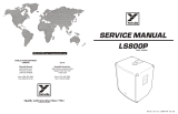
Solder some nice, long lengths of wire to the board connections for 9V, GND, IN and OUT.
Connect IN and OUT to the jacks as shown. Connect all the GNDs together (twist them up
and add a small amount of solder to tack it). Connect the battery + lead to the 9V wire,
same method. Plug in. Go!
If it works, crack on and do your switch wiring. If not... aw man. At least you know the
problem is with the circuit. Find out why, get it working, THEN worry about the switch etc.
BATTERY
IN OUT
Your nice, new circuit board
INCLUDING WIRED POTS!!!!
IN 9V GND OUT

Wiring shown above will disconnect the battery when you remove the jack plug
from the input, and also when a DC plug is inserted.
The Board GND connections don’t all have to directly attach to the board. You
can run a couple of wires from the DC connector, one to the board, another to
the IN jack, then daisy chain that over to the OUT jack.
It doesn’t matter how they all connect, as long as they do.
This circuit is standard, Negative GND. Your power supply should be Tip
Negative / Sleeve Positive. That’s the same as your standard pedals (Boss etc),
and you can safely daisy-chain your supply to this pedal.
L
E
D
BOARD
OUT
BOARD
9V
BOARD
GND
BOARD
GND
BOARD
GND
BOARD
INPUT
BATTERY
+
IN
OUT
L
E
D
BOARD
GND
BOARD
LED+
+
Wire it up (if using a daughterboard please refer to the relevant document)

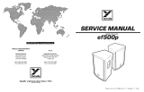
This template is a rough guide only. You should ensure correct marking of your
enclosure before drilling. You use this template at your own risk.
Pedal Parts Ltd can accept no responsibility for incorrect drilling of enclosures.
FuzzDog.co.uk
Drilling template
Hammond 1590B
60 x 111 x 31mm
It’s a good idea to drill the pot and
toggle switch holes 1mm bigger if
you’re board-mounting them.
Wiggle room = good!
Recommended drill sizes:
Pots 7mm
Jacks 10mm
Footswitch 12mm
DC Socket 12mm
27mm
35mm
17.5mm
/