Page is loading ...

RELEASED
4-30-18
REFERENCE NUMBER
INS-2321-00
40429 Brickyard Drive • Madera, CA 93636 • USA
559.438.5800 • FAX 559.438.5900
www.bklighting.com • [email protected]
B-K LIGHTING
THIS DOCUMENT CONTAINS PROPRIETARY INFORMATION OF B-K LIGHTING, INC. AND ITS RECEIPT OR POSSESSION DOES NOT CONVEY ANY RIGHTS TO REPRODUCE, DISCLOSE ITS CONTENTS, OR TO MANUFACTURE, USE OR SELL ANYTHING IT MAY
DESCRIBE. REPRODUCTION, DISCLOSURE OR USE WITHOUT SPECIFIC WRITTEN AUTHORIZATION OF B-K LIGHTING, INC. IS STRICTLY FORBIDDEN.
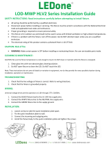
IMPORTANT SAFETY INFORMATION - READ, FOLLOW, AND SAVE THESE INSTALLATION INSTRUCTIONS
TOOLS
NEEDED:
By Others
ALPINE SURFACE DOWNLIGHT™
Remote Driver - Solid State LED
· Suitable for wet locations
IMPORTANT LISTINGS AND CERTIFICATIONS
Warning Hot Surface
Installation Instructions
3/32” Allen Wrench
Waterproof Wire Connectors
Mounting Hardware
Mounting Hardware for Substrate
Low Voltage
Mounting
Plate
Installation
Tether
REMOTE WIRING
LED Driver
Remote driver installations require inter-connected
wiring between the LED and driver (by others). Drivers
have specific wiring requirements between these
components. Driver manufacturers regularly recommend
the following wiring details for such installations:
• Do not exceed 50 foot overall wiring distance
using 12 gauge copper wire.
Failure to comply with specific wiring
requirements will void product warranty.
DRIVER HOUSING REQUIRED
Please refer to specified remote driver housing
documentation for detailed installation instructions.
REMOTE DRIVER HOUSINGS:
PM3RM - Universal Power Module 3 Remote
PM3DRM - Universal Power Module 3 Dual Remote
RM - Remote Wall Mount
DRM - Dual Remote Wall Mount
PM2RM PM2DRM PM3RM PM3DRM
PM3RM &
PM3DRM
PM2RM PM2DRM PM3RM PM3DRM
RM &
DRM
• Product must be installed by a qualified person in a manner
consistent with its intended use and in compliance with the
National Electrical Code, Canadian Electrical Code, and all Local and
Provincial Codes.
• Follow product label information and instructions.
• Qualified Personnel with appropriate personal protective
equipment must perform all servicing of this product.
• Before wiring to power supply and during servicing, turn off and
lock out power at fuse or circuit breaker before service.
• The use of accessory equipment not recommended by the
manufacturer or installed contrary to instructions may cause an
unsafe condition. The use of damaged components may cause an
unsafe condition and void product warranty.
IMPORTANT SAFETY INFORMATION - READ, FOLLOW, AND SAVE ALL SAFETY
AND INSTALLATION INSTRUCTIONS
• Do not block light emanating from product in whole or part, as
this may cause an unsafe condition.
• Never operate the fixture with missing or damaged lens.
Lens must be cleaned on regular basis.
• Entire fixture may become extremely hot. Do not touch hot
lens or fixture body.
• Replace LED assembly only with correct wattage and type of
power supply appropriate for LED assembly.
• All gaskets, o-rings and sealing surfaces must be kept clean
during installation and service; failure to do this may cause an
unsafe condition and void product warranty.
INSTRUCTIONS PERTAINING TO
A RISK OF FIRE, OR INJURY TO
PERSONS IMPORTANT SAFETY
INSTRUCTIONS
Lighted fixture is HOT!
WARNING - To reduce the risk of
FIRE OR INJURY TO PERSONS:
Turn off/unplug and allow to cool before replacing LED.
Fixture gets HOT quickly! Contact only switch/plug when
turning on. Do not touch hot lens, guard, or enclosure.
Keep fixture away from materials that may burn.
Do not operate the luminaire fitting with a missing or
damaged shield. Do not touch the source at any time. Use
a soft cloth or gloves. Oil from skin may cause damage.
SAVE THESE INSTRUCTIONS
ACV™ Valve (Interior View)

40429 Brickyard Drive • Madera, CA 93636 • USA
559.438.5800 • FAX 559.438.5900
www.bklighting.com • [email protected]
B-K LIGHTING
PROJECT:
TYPE:
IMPORTANT SAFETY INFORMATION LISTED ON REVERSE
READ, FOLLOW, AND SAVE ALL SAFETY AND INSTALLATION INSTRUCTIONS
RELEASED
4-30-18
REFERENCE NUMBER
INS-2321-00
Installation Instructions
Phase 1 - Rough In
Installation of Back box
1. Install Conduit (By Others) to be used with
this product.
2. Install junction box (By Others) so that
front face is flush with finished ceiling. Seal
building envelope as per NEC.
3. Connect box to conduit and pull wires for
connections (See wiring diagram).
Additional Info
• Please follow National and Local electrical codes for your area.
• Use 4” round cast box (By Others)
• Suitable for through wire
• Suitable for installation into combustible materials.
• Rated for 90° C.
• Junction box, universal mounting ring screws, box mounting hardware
and gaskets (By Others)
Phase 2 - Finish Installation of Fixture
1. There are two holes for junction box mounting
in mounting plate. Install mounting plate to
junction box with mounting hardware (Hardware
By Others).
4. Pull remote wiring through mounting plate.
Make watertight connections from remote
driver secondary side to fixture leads using
waterproof wire connectors (By Others). See
wiring diagram.
WIRING DIAGRAM
LINE
Red
FIXTURE
COM
Hydrolock
Plate
Black
GROUND
Driver
White
Black
Green
DIM +
DIM -
Black
White
Hydrolock
Plate
Green
Driver
White
Black
White
Blue
Green
LINE
COM
GROUND
Orange
Orange
Brown
Blue
Black
Gray
FIXTURE
FIXTURE
Green
Green
LINE
Red
FIXTURE
COM
Driver
Black
GROUND
DIM +
DIM -
GROUND IN HOUSING
LINE
Red
FIXTURE
COM
Driver
Black
DIM +
DIM -
GROUND ON PLATE
LINE
Red
FIXTURE
COM
Driver
Black
DIM +
DIM -
HP2RM
HP2 TR
TMB
PCIII
Generic TR
GROUND IN HOUSING
LINE
Quick
Connect
COM
Driver FIXTURE
DIM +
DIM -
PM3
GROUND IN HOUSING
LINE
Quick
Connect
COM
Driver FIXTURE
DIM +
DIM -
Quick
Connect
Driver FIXTURE
DIM +
DIM -
PM3D
GROUND IN HOUSING
LINE
COM
Remote
Driver
DIM +
DIM -
Fixture
Fixture
PM3RM
GROUND ON PLATE
LINE
COM
Driver
DIM +
DIM -
PCIII
Quick
Connect
FIXTURE
LINE
Red
FIXTURE
COM
Remote
Driver
Black
DIM +
DIM -
MA/AP
GROUND
GROUND IN HOUSING
LINE
COM
Remote
Driver
DIM +
DIM -
DIM +
DIM -
PM3DRM
Fixture
Fixture
Remote
Driver
Fixture
Fixture
5. Place connections through wireway into junction
box. Mount fixture over mounting plate, then
secure with three (3) #10-32 screws using 3/32”
Allen wrench. Do not overtighten.
3. Slowly lower the fixture until tether is taut.
NOTE: Installation tether supplied is designed
as an installation aid and NOT a safety cable.
Do not add weight to, or drop fixture.
ALPINE SURFACE DOWNLIGHT™
Remote Driver - Solid State LED
2. There are two holes for mounting the mounting
plate to substrate. Secure mounting plate to
substrate with mounting hardware appropriate
for substrate material (Hardware By Others). Seal
building envelope as per NEC.

RELEASED
1-30-18
REFERENCE NUMBER
INS-2321-02
40429 Brickyard Drive • Madera, CA 93636 • USA
559.438.5800 • FAX 559.438.5900
www.bklighting.com • [email protected]
B-K LIGHTING
THIS DOCUMENT CONTAINS PROPRIETARY INFORMATION OF B-K LIGHTING, INC. AND ITS RECEIPT OR POSSESSION DOES NOT CONVEY ANY RIGHTS TO REPRODUCE, DISCLOSE ITS CONTENTS, OR TO MANUFACTURE, USE OR SELL ANYTHING IT MAY
DESCRIBE. REPRODUCTION, DISCLOSURE OR USE WITHOUT SPECIFIC WRITTEN AUTHORIZATION OF B-K LIGHTING, INC. IS STRICTLY FORBIDDEN.
LED BOARD / OPTICS
Wall Wash
Replacement
IMPORTANT SAFETY INFORMATION - READ, FOLLOW, AND SAVE THESE INSTALLATION INSTRUCTIONS
Warning Hot Surface
TOOLS
NEEDED:
By Others
7/64”, 3/32” & 0.050” Allen Wrench
Small Pick Tool
Thermal Paste (Supplied)
To Replace Components
1. Loosen (3) #10-32 set screws on base with 3/32”
Allen wrench. Retain screws in fixture. Gently slide
down fixture from mounting base to access ACV™
valve. Do not pull on install tether or leads.
NOTE: Installation tether supplied is designed as
an installation aid and NOT a safety cable. Do not
add weight to, or drop fixture.
5. Loosen, then remove two (2) #4-40 screws from LED
module using 0.050” Allen wrench.
Fragile! Do not pull on connector or wiring.
Handle with care.
6. Carefully remove LED module from heatsink.
Do not pull on connector or wiring. Handle with
care.
7. Use small pick tool to push connector off LED board
through two small slots behind connector. Once
loose, lift connector upwards and off board.
4. Loosen four (4) #6-32 screws on wall wash optic
holder using 7/64” Allen wrench, then gently pull
away to remove from heatsink.
8. Spread thin, even layer of thermal paste on back
of new LED module. Place new LED module onto
heatsink, lining up module with holes for screws.
Tighten two (2) #4-40 screws using 0.050” Allen
wrench to secure LED module to heatsink.
3. Press patented Anti-Condensation Valve (ACV™)
to release vacuum created inside the fixture
during normal use. The valve is spring-loaded, by
depressing it, air is allowed to re-enter the chamber
and the pressure is then equalized. When the air-
pressure equalizes the cap will release from body to
allow service.
2. Loosen (3) #10-32 set screws on cap with 3/32”
Allen wrench. Retain screws in cap.
9. Place new LED module onto heatsink, lining up
module with holes for screws. Press connector
straight downwards into slot on module to snap
into place.
Connector will only fit in one direction.

LED BOARD / OPTICS
Wall Wash
Replacement
RELEASED
1-30-18
REFERENCE NUMBER
INS-2321-02
40429 Brickyard Drive • Madera, CA 93636 • USA
559.438.5800 • FAX 559.438.5900
www.bklighting.com • [email protected]
B-K LIGHTING
THIS DOCUMENT CONTAINS PROPRIETARY INFORMATION OF B-K LIGHTING, INC. AND ITS RECEIPT OR POSSESSION DOES NOT CONVEY ANY RIGHTS TO REPRODUCE, DISCLOSE ITS CONTENTS, OR TO MANUFACTURE, USE OR SELL ANYTHING IT MAY
DESCRIBE. REPRODUCTION, DISCLOSURE OR USE WITHOUT SPECIFIC WRITTEN AUTHORIZATION OF B-K LIGHTING, INC. IS STRICTLY FORBIDDEN.
IMPORTANT SAFETY INFORMATION - READ, FOLLOW, AND SAVE THESE INSTALLATION INSTRUCTIONS
12. Place cap on fixture and tighten three (3) #10-32 set
screws using 3/32” Allen wrench. Tighten screw to 1/2
in-lbs. Top of screw should sit flush with fixture cap.
Warning: Do not over tighten set screw. Doing
so will compromise O-Ring seal and will void
warranty.
10. Tighten two (2) #4-40 screws using .050” Allen
wrench to secure LED module to heatsink. 11. Place wall wash optic over LED module, lining up
screw locations with holes in heatsink. Secure wall
wash optic to heatsink with four (4) #6-32 screws
using 7/64” Allen wrench.
13. Place connections through wireway into junction
box. Mount fixture over mounting plate, then secure
with three (3) #10-32 screws using 5/32” Allen
wrench. Do not overtighten.

RELEASED
1-30-18
REFERENCE NUMBER
INS-2321-03
40429 Brickyard Drive • Madera, CA 93636 • USA
559.438.5800 • FAX 559.438.5900
www.bklighting.com • [email protected]
B-K LIGHTING
THIS DOCUMENT CONTAINS PROPRIETARY INFORMATION OF B-K LIGHTING, INC. AND ITS RECEIPT OR POSSESSION DOES NOT CONVEY ANY RIGHTS TO REPRODUCE, DISCLOSE ITS CONTENTS, OR TO MANUFACTURE, USE OR SELL ANYTHING IT MAY
DESCRIBE. REPRODUCTION, DISCLOSURE OR USE WITHOUT SPECIFIC WRITTEN AUTHORIZATION OF B-K LIGHTING, INC. IS STRICTLY FORBIDDEN.
LED BOARD / OPTICS
Dome Lens
Replacement
IMPORTANT SAFETY INFORMATION - READ, FOLLOW, AND SAVE THESE INSTALLATION INSTRUCTIONS
Warning Hot Surface
TOOLS
NEEDED:
By Others
5/32”, 0.050” & 1/16” Allen Wrench
Small Pick Tool
Thermal Paste (Supplied)
To Replace Components
5. Loosen two (2) #4-40 flat head screws with 1/16”
Allen wrench. Gently pull optic holder off heatsink,
being careful not to pull LED module along with it.
Fragile! Do not pull on connector or wiring.
Handle with care.
6. Carefully remove LED module from heatsink.
Do not pull on connector or wiring. Handle with
care.
7. Use small pick tool to push connector off LED board
through two small slots behind connector. Once
loose, lift connector upwards and off board.
Connector will only fit in one direction.
4. Loosen three (3) #6-32 set screws on side of dome
lens optic holder using 1/16” Allen wrench. Gently
remove dome lens.
9. Place new LED module onto heatsink, lining up
module with holes for screws. Press connector
straight downwards into slot on module to snap into
place.
8. Spread thin, even layer of thermal paste on back
of new LED module. Place new LED module onto
heatsink, lining up module with holes for screws.
Tighten two (2) #4-40 screws using .050” Allen
wrench to secure LED module to heatsink.
1. Loosen (3) #10-32 set screws on base with 3/32”
Allen wrench. Retain screws in fixture. Gently slide
down fixture from mounting base to access ACV™
valve. Do not pull on install tether or leads.
NOTE: Installation tether supplied is designed as
an installation aid and NOT a safety cable. Do not
add weight to, or drop fixture.
3. Press patented Anti-Condensation Valve (ACV™) to
release vacuum created inside the fixture during
normal use. The valve is spring-loaded, by depressing
it, air is allowed to re-enter the chamber and the
pressure is then equalized. When the air-pressure
equalizes the cap will release from body to allow
service.
2. Loosen (3) #10-32 set screws on cap with 3/32” Allen
wrench. Retain screws in cap.

LED BOARD / OPTICS
Dome Lens
Replacement
RELEASED
1-30-18
REFERENCE NUMBER
INS-2321-03
40429 Brickyard Drive • Madera, CA 93636 • USA
559.438.5800 • FAX 559.438.5900
www.bklighting.com • [email protected]
B-K LIGHTING
THIS DOCUMENT CONTAINS PROPRIETARY INFORMATION OF B-K LIGHTING, INC. AND ITS RECEIPT OR POSSESSION DOES NOT CONVEY ANY RIGHTS TO REPRODUCE, DISCLOSE ITS CONTENTS, OR TO MANUFACTURE, USE OR SELL ANYTHING IT MAY
DESCRIBE. REPRODUCTION, DISCLOSURE OR USE WITHOUT SPECIFIC WRITTEN AUTHORIZATION OF B-K LIGHTING, INC. IS STRICTLY FORBIDDEN.
IMPORTANT SAFETY INFORMATION - READ, FOLLOW, AND SAVE THESE INSTALLATION INSTRUCTIONS
12. Place cap on fixture and tighten set
screw. Tighten screw to 1/2 in-lbs. Top
of screw should sit flush with fixture cap.
Warning: Do not over tighten set screw. Doing
so will compromise O-Ring seal and will void
warranty.
10. Tighten two (2) #4-40 flat head screws using 1/16”
Allen wrench to secure LED module and optic holder
to heatsink.
11. Place dome lens into optic holder. Tighten three (3)
#6-32 set screws on side of dome lens optic holder
using 1/16” Allen wrench.
13. Place connections through wireway into junction
box. Mount fixture over mounting plate, then secure
with three (3) #10-32 screws using 3/32” Allen
wrench. Do not overtighten.

Warning High Voltage Hot Surface
NEMA 3R Remote Power Supply
Solid State LED
Installation Instructions
REMOTE WIRING
LED Driver
Remote driver installations require inter-connected
wiring between the LED and driver (by others). Drivers
have specific wiring requirements between these
components. Driver manufacturers regularly recommend
the following wiring details for such installations:
• Do not exceed 50 foot overall wiring distance
using 12 gauge copper wire.
Failure to comply with specific wiring
requirements will void product warranty.
· Suitable for wet locations
IMPORTANT LISTINGS AND CERTIFICATIONS
RELEASE DATE
12-8-17
REFERENCE NUMBER
INS-2235-00
40429 Brickyard Drive • Madera, CA 93636 • USA
559.438.5800 • FAX 559.438.5900
www.bklighting.com • [email protected]
B-K LIGHTING
THIS DOCUMENT CONTAINS PROPRIETARY INFORMATION OF B-K LIGHTING, INC. AND ITS RECEIPT OR POSSESSION DOES NOT CONVEY ANY RIGHTS TO REPRODUCE, DISCLOSE ITS CONTENTS, OR TO MANUFACTURE, USE OR SELL ANYTHING IT MAY
DESCRIBE. REPRODUCTION, DISCLOSURE OR USE WITHOUT SPECIFIC WRITTEN AUTHORIZATION OF B-K LIGHTING, INC. IS STRICTLY FORBIDDEN.
IMPORTANT SAFETY INFORMATION - READ, FOLLOW, AND SAVE THESE INSTALLATION INSTRUCTIONS
NEEDED
FOR
INSTALLATION:
By Others
Driver
Dual Drivers
RM - Single Remote Housing
DRM - Dual Remote Housing
Cover
Cover
Terminal
Block
Terminal
Block
(A)
Terminal Block (B)
(Dimming Controls)
1/8” Allen Wrench
Phillips Screwdriver
Level
Hammer
Mounting Hardware
• Product must be installed by a qualified person in a manner
consistent with its intended use and in compliance with the
National Electrical Code, Canadian Electrical Code, and all Local and
Provincial Codes.
• Follow product label information and instructions.
• Qualified Personnel with appropriate personal protective
equipment must perform all servicing of this product.
• Before wiring to power supply and during servicing, turn off and
lock out power at fuse or circuit breaker before service.
• The use of accessory equipment not recommended by the
manufacturer or installed contrary to instructions may cause an
unsafe condition. The use of damaged components may cause an
unsafe condition and void product warranty.
IMPORTANT SAFETY INFORMATION - READ, FOLLOW, AND SAVE ALL SAFETY
AND INSTALLATION INSTRUCTIONS
• Do not block light emanating from product in whole or part, as
this may cause an unsafe condition.
• Never operate the fixture with missing or damaged lens.
Lens must be cleaned on regular basis.
• Entire fixture may become extremely hot. Do not touch hot
lens or fixture body.
• Replace LED assembly only with correct wattage and type of
power supply appropriate for LED assembly.
• All gaskets, o-rings and sealing surfaces must be kept clean
during installation and service; failure to do this may cause an
unsafe condition and void product warranty.
INSTRUCTIONS PERTAINING TO
A RISK OF FIRE, OR INJURY TO
PERSONS IMPORTANT SAFETY
INSTRUCTIONS
Lighted fixture is HOT!
WARNING - To reduce the risk of
FIRE OR INJURY TO PERSONS:
Turn off/unplug and allow to cool before replacing LED.
Fixture gets HOT quickly! Contact only switch/plug when
turning on. Do not touch hot lens, guard, or enclosure.
Keep fixture away from materials that may burn.
Do not operate the luminaire fitting with a missing or
damaged shield. Do not touch the source at any time. Use
a soft cloth or gloves. Oil from skin may cause damage.
SAVE THESE INSTRUCTIONS

RELEASE DATE
12-8-17
REFERENCE NUMBER
INS-2235-00
40429 Brickyard Drive • Madera, CA 93636 • USA
559.438.5800 • FAX 559.438.5900
www.bklighting.com • [email protected]
B-K LIGHTING
IMPORTANT SAFETY INFORMATION LISTED ON REVERSE
READ, FOLLOW, AND SAVE ALL SAFETY AND INSTALLATION INSTRUCTIONS
NEMA 3R Remote Power Supply
Solid State LED
Installation Instructions
4. Connect conduit connector through female
threaded conduit entry.
NOTE: Surface conduit is a common entrance
for water if not properly sealed. Seal
connector threads and conduit with a suitable
sealant (Teflon tape, adhesive, etc.). Sealing
the conduit after knockouts are removed is
required to maintain warranty.
8. Re-attach cover. Tighten cover screw.
5. Pull branch circuit wiring necessary for
installation (By Others). Pull dimming control
wiring necessary for installation (By Others).
Single Remote Driver with Dimming Controls
7. Connect branch circuit to terminal block. Connect incoming ground to ground wire provided on NEMA 3R
housing. Connect secondary lamp leads to terminal. See labels on terminal block for additional information..
6. Pull secondary lamp leads necessary for
installation though dedicated conduit. (By
Others).
NOTE: Failure to comply with specific wiring
requirements will void product warranty.
2. Attach the NEMA 3R housing at mounting holes
with ¼” fasteners (By Others). Use suitable
mounting hardware for surface. Use level to
ensure a level install.
NOTE: Many methods exist to bolt to a
flat surface. The housing is provided with
mounting brackets with ¼” holes.
Housing Installation
3. Remove Knockout(s) with hammer as needed
from the NEMA 3R housing. Leave remaining
unused knockouts in place to maintain seal.
1. Remove cover by removing #10-24 cover screw
using a 1/8” Allen wrench.
DIM
COM
LED
-
DIM
LED
+
DIM
COM
LED
-
DIM
LED
+

120-208-
240-277
VOLT
120-208-
240-277
VOLT
COM
LAMP
1
LAMP
COM
1
LED
+
1
LED
1
LAMP
2
LAMP
COM
2
LED
+
2
LED
2
DIM
1
DIM
COM
1
DIM
+
1
DIM
1
DIM
2
DIM
COM
2
DIM
+
2
DIM
2
7. Terminal A is for circuit branch wiring and fixture
leads. Terminal B is for dimming controls. The
grounding screw is located to the upper right of
terminal A.
120-208-
240-277
VOLT
120-208-
240-277
VOLT
COM
LAMP
1
LAMP
COM
1
LED
+
1
LED
1
LAMP
2
LAMP
COM
2
LED
+
2
LED
2
DIM
1
DIM
COM
1
DIM
+
1
DIM
1
DIM
2
DIM
COM
2
DIM
+
2
DIM
2
8. Terminal Block A - Connect branch circuit to terminal block. Connect incoming ground to ground wire
provided on NEMA 3R housing. Connect secondary lamp leads to terminal A. See labels on terminal block for
additional information.
4. Connect conduit connector through female
threaded conduit entry.
NOTE: Surface conduit is a common entrance
for water if not properly sealed. Seal
connector threads and conduit with a suitable
sealant (Teflon tape, adhesive, etc.). Sealing
the conduit after knockouts are removed is
required to maintain warranty.
5. Pull branch circuit wiring necessary for
installation (By Others). Pull dimming control
wiring necessary for installation (By Others).
Dual Remote Driver with Dimming Controls
6. Pull secondary lamp leads necessary for
installation though dedicated conduit. (By
Others).
NOTE: Failure to comply with specific wiring
requirements will void product warranty.
NEMA 3R Remote Power Supply
Solid State LED
Installation Instructions
10. Re-attach cover. Tighten cover screw.
RELEASE DATE
12-8-17
REFERENCE NUMBER
INS-2235-00
40429 Brickyard Drive • Madera, CA 93636 • USA
559.438.5800 • FAX 559.438.5900
www.bklighting.com • [email protected]
B-K LIGHTING
IMPORTANT SAFETY INFORMATION LISTED ON REVERSE
READ, FOLLOW, AND SAVE ALL SAFETY AND INSTALLATION INSTRUCTIONS
120-208-
240-277
VOLT
120-208-
240-277
VOLT
COM
LAMP
1
LAMP
COM
1
LED
+
1
LED
1
LAMP
2
LAMP
COM
2
LED
+
2
LED
2
DIM
1
DIM
COM
1
DIM
+
1
DIM
1
DIM
2
DIM
COM
2
DIM
+
2
DIM
2
9. Terminal Block B - Connect incoming dimming
controls to terminal block. See labels on terminal
block for additional information.
A
B
Ground

RELEASED
12-8-17
REFERENCE NUMBER
INS-2187-00
40429 Brickyard Drive • Madera, CA 93636 • USA
559.438.5800 • FAX 559.438.5900
www.bklighting.com • [email protected]
B-K LIGHTING
THIS DOCUMENT CONTAINS PROPRIETARY INFORMATION OF B-K LIGHTING, INC. AND ITS RECEIPT OR POSSESSION DOES NOT CONVEY ANY RIGHTS TO REPRODUCE, DISCLOSE ITS CONTENTS, OR TO MANUFACTURE, USE OR SELL ANYTHING IT MAY
DESCRIBE. REPRODUCTION, DISCLOSURE OR USE WITHOUT SPECIFIC WRITTEN AUTHORIZATION OF B-K LIGHTING, INC. IS STRICTLY FORBIDDEN.
IMPORTANT SAFETY INFORMATION - READ, FOLLOW, AND SAVE THESE INSTALLATION INSTRUCTIONS
TOOLS
NEEDED:
By Others
· Suitable for wet locations
IMPORTANT LISTINGS AND CERTIFICATIONS
Warning High Voltage
Adjustable
Tree Strap
Hot Surface
Installation Instructions1/8” Allen Wrench
Waterproof Wire Connectors
Hammer
Phillips Screwdriver
* UPM is covered in whole or in part by US patent #6,940,012
PM3RM
Housing
Knockouts
Faceplate
REMOTE WIRING
LED Driver
Remote driver installations require inter-connected
wiring between the LED and driver (by others). Drivers
have specific wiring requirements between these
components. Driver manufacturers regularly recommend
the following wiring details for such installations:
• Do not exceed 50 foot overall wiring distance
using 12 gauge copper wire.
Failure to comply with specific wiring
requirements will void product warranty.
Driver
PM3RM TREE STRAP™
Driver Housing
• Product must be installed by a qualified person in a manner
consistent with its intended use and in compliance with the
National Electrical Code, Canadian Electrical Code, and all Local and
Provincial Codes.
• Follow product label information and instructions.
• Qualified Personnel with appropriate personal protective
equipment must perform all servicing of this product.
• Before wiring to power supply and during servicing, turn off and
lock out power at fuse or circuit breaker before service.
• The use of accessory equipment not recommended by the
manufacturer or installed contrary to instructions may cause an
unsafe condition. The use of damaged components may cause an
unsafe condition and void product warranty.
IMPORTANT SAFETY INFORMATION - READ, FOLLOW, AND SAVE ALL SAFETY
AND INSTALLATION INSTRUCTIONS
• Do not block light emanating from product in whole or part, as
this may cause an unsafe condition.
• Never operate the fixture with missing or damaged lens.
Lens must be cleaned on regular basis.
• Entire fixture may become extremely hot. Do not touch hot
lens or fixture body.
• Replace LED assembly only with correct wattage and type of
power supply appropriate for LED assembly.
• All gaskets, o-rings and sealing surfaces must be kept clean
during installation and service; failure to do this may cause an
unsafe condition and void product warranty.
INSTRUCTIONS PERTAINING TO
A RISK OF FIRE, OR INJURY TO
PERSONS IMPORTANT SAFETY
INSTRUCTIONS
Lighted fixture is HOT!
WARNING - To reduce the risk of
FIRE OR INJURY TO PERSONS:
Turn off/unplug and allow to cool before replacing LED.
Fixture gets HOT quickly! Contact only switch/plug when
turning on. Do not touch hot lens, guard, or enclosure.
Keep fixture away from materials that may burn.
Do not operate the luminaire fitting with a missing or
damaged shield. Do not touch the source at any time. Use
a soft cloth or gloves. Oil from skin may cause damage.
SAVE THESE INSTRUCTIONS

40429 Brickyard Drive • Madera, CA 93636 • USA
559.438.5800 • FAX 559.438.5900
www.bklighting.com • [email protected]
B-K LIGHTING
PROJECT:
TYPE:
IMPORTANT SAFETY INFORMATION LISTED ON REVERSE
READ, FOLLOW, AND SAVE ALL SAFETY AND INSTALLATION INSTRUCTIONS
RELEASED
12-8-17
REFERENCE NUMBER
INS-2187-00
Installation Instructions
LAMP
BLUE
WHITE
GROUND
QUICK DISCONNECT
LINE (BLACK)
NEUTRAL (WHITE)
GROUND (GREEN)
BARE WIRE
IN UPM
RED
BLACK
BLUE
WHITE
GREEN
BALLAST
GroundHotNeutral
LAMP
BLUE
WHITE
GROUND
QUICK DISCONNECT
LINE (BLACK)
NEUTRAL (WHITE)
GROUND (GREEN)
BARE WIRE
IN UPM
RED
BLACK
BLUE
WHITE
GREEN
BALLAST
GroundHotNeutral
2. Remove Patented Knockout(s) as necessary
from the inside of the UPM housing. Leave
remaining unused knockouts in place to
maintain seal.
NOTE: Patented design featuring a silicone
‘O’ Ring allowing knockout to be tapped
back into place to renew seal integrity.
3. Use adjustable strap provided to attach UPM
housing to tree. Tighten by pulling on the
adjustable strap until secure.
LAMP
BLUE
WHITE
GROUND
QUICK DISCONNECT
LINE (BLACK)
NEUTRAL (WHITE)
GROUND (GREEN)
BARE WIRE
IN UPM
RED
BLACK
BLUE
WHITE
GREEN
BALLAST
GroundHotNeutral
4. Thread safety cable through hole on the back of the
UPM housing. Feed safety cable through opposing
ends of the connector. Pull on wires to assure the
connection is secure. Leave enough slack in safety
cable for tree growth. Adjustments can be made
by pressing release spring with a pin or 3/64” Allen
tool.
LAMP
BLUE
WHITE
GROUND
QUICK DISCONNECT
LINE (BLACK)
NEUTRAL (WHITE)
GROUND (GREEN)
BARE WIRE
IN UPM
RED
BLACK
BLUE
WHITE
GREEN
BALLAST
GroundHotNeutral
LAMP
BLUE
WHITE
GROUND
QUICK DISCONNECT
LINE (BLACK)
NEUTRAL (WHITE)
GROUND (GREEN)
BARE WIRE
IN UPM
RED
BLACK
BLUE
WHITE
GREEN
BALLAST
GroundHotNeutral
6. Pull branch circuit wiring and dimming control
wiring necessary for installation (By Others).
7. Attach tether wire under screw head at the base
of the UPM housing and tighten. Slowly lower the
faceplate until tether is taut.
NOTE: Faceplate tether supplied with UPM is
designed as an installation aid and NOT a safety
cable. Do not add weight to, or drop faceplate.
LAMP
BLUE
WHITE
GROUND
QUICK DISCONNECT
LINE (BLACK)
NEUTRAL (WHITE)
GROUND (GREEN)
BARE WIRE
IN UPM
RED
BLACK
BLUE
WHITE
GREEN
BALLAST
GroundHotNeutral
5. Connect 3/4” conduit connector through
female threaded conduit entry.
NOTE: Surface conduit is a common entrance
for water if not properly sealed. Seal
connector threads and conduit pipe with
a suitable sealant (Teflon tape, adhesive,
etc). Sealing the conduit after knockouts are
removed is required to maintain warranty.
1. Loosen (6) #10-24 captive screws using a 1/8” Allen
wrench to remove faceplate of UPM housing.
PM3RM TREE STRAP™
Driver Housing
LINE
Red
FIXTURE
COM
Hydrolock
Plate
Black
GROUND
Driver
White
Black
Green
DIM +
DIM -
Black
White
Hydrolock
Plate
Green
Driver
White
Black
White
Blue
Green
LINE
COM
GROUND
Orange
Orange
Brown
Blue
Black
Gray
FIXTURE
FIXTURE
Green
Green
LINE
Red
FIXTURE
COM
Driver
Black
GROUND
DIM +
DIM -
GROUND IN HOUSING
LINE
Red
FIXTURE
COM
Driver
Black
DIM +
DIM -
GROUND ON PLATE
LINE
Red
FIXTURE
COM
Driver
Black
DIM +
DIM -
HP2RM
HP2 TR
TMB
PCIII
Generic TR
GROUND IN HOUSING
LINE
Quick
Connect
COM
Driver FIXTURE
DIM +
DIM -
PM3
GROUND IN HOUSING
LINE
Quick
Connect
COM
Driver FIXTURE
DIM +
DIM -
Quick
Connect
Driver FIXTURE
DIM +
DIM -
PM3D
GROUND IN HOUSING
LINE
COM
Remote
Driver
DIM +
DIM -
Fixture
Fixture
PM3RM
GROUND ON PLATE
LINE
COM
Driver
DIM +
DIM -
PCIII
Quick
Connect
FIXTURE
LINE
Red
FIXTURE
COM
Remote
Driver
Black
DIM +
DIM -
MA/APGROUND
GROUND IN HOUSING
LINE
COM
Remote
Driver
DIM +
DIM -
DIM +
DIM -
PM3DRM
Fixture
Fixture
Remote
Driver
Fixture
Fixture
WIRING DIAGRAM
8. Use waterproof wire connectors (By Others) to
connect driver primary leads to branch circuit
wires. Connect incoming ground to ground
wire provided in UPM housing. Connect
incoming dimming control wires to driver
dimming controls. See wiring diagram.
9. Remove two (2) #8-32 screws in UPM housing
using Phillips screwdriver.

LAMP
BLUE
WHITE
GROUND
QUICK DISCONNECT
LINE (BLACK)
NEUTRAL (WHITE)
GROUND (GREEN)
BARE WIRE
IN UPM
RED
BLACK
BLUE
WHITE
GREEN
BALLAST
GroundHotNeutral
LAMP
BLUE
WHITE
GROUND
QUICK DISCONNECT
LINE (BLACK)
NEUTRAL (WHITE)
GROUND (GREEN)
BARE WIRE
IN UPM
RED
BLACK
BLUE
WHITE
GREEN
BALLAST
GroundHotNeutral
12. Make sure UPM housing gasket is free of
any dirt or debris. Attach the faceplate by
tightening the (6) #10-24 captive screws
evenly using a 1/8” Allen wrench.
PROJECT:
TYPE:
Installation Instructions
40429 Brickyard Drive • Madera, CA 93636 • USA
559.438.5800 • FAX 559.438.5900
www.bklighting.com • [email protected]
B-K LIGHTING
IMPORTANT SAFETY INFORMATION LISTED ON REVERSE
READ, FOLLOW, AND SAVE ALL SAFETY AND INSTALLATION INSTRUCTIONS
RELEASED
12-8-17
REFERENCE NUMBER
INS-2187-00
PM3RM TREE STRAP™
Driver Housing
10. Slide driver feet under two screws in UPM housing
and tighten screws using Phillips screwdriver.
11. Reinstall #8-32 screws on other side of driver and
tighten to secure driver to UPM housing.

RELEASED
12-8-17
REFERENCE NUMBER
INS-2187-00
40429 Brickyard Drive • Madera, CA 93636 • USA
559.438.5800 • FAX 559.438.5900
www.bklighting.com • [email protected]
B-K LIGHTING
THIS DOCUMENT CONTAINS PROPRIETARY INFORMATION OF B-K LIGHTING, INC. AND ITS RECEIPT OR POSSESSION DOES NOT CONVEY ANY RIGHTS TO REPRODUCE, DISCLOSE ITS CONTENTS, OR TO MANUFACTURE, USE OR SELL ANYTHING IT MAY
DESCRIBE. REPRODUCTION, DISCLOSURE OR USE WITHOUT SPECIFIC WRITTEN AUTHORIZATION OF B-K LIGHTING, INC. IS STRICTLY FORBIDDEN.
IMPORTANT SAFETY INFORMATION - READ, FOLLOW, AND SAVE THESE INSTALLATION INSTRUCTIONS
· Suitable for wet locations
IMPORTANT LISTINGS AND CERTIFICATIONS
Warning High Voltage
Surface Mount
Hot Surface
Installation Instructions
* UPM is covered in whole or in part by US patent #6,940,012
PM3RM
Housing
Knockouts
Faceplate
1/8” Allen Wrench
Waterproof Wire Connectors
Hammer
Phillips Screwdriver
1/4” Drill Bit and Drill
Mounting Hardware
NEEDED
FOR
INSTALLATION:
By others
REMOTE WIRING
LED Driver
Remote driver installations require inter-connected
wiring between the LED and driver (by others). Drivers
have specific wiring requirements between these
components. Driver manufacturers regularly recommend
the following wiring details for such installations:
• Do not exceed 50 foot overall wiring distance
using 12 gauge copper wire.
Failure to comply with specific wiring
requirements will void product warranty.
Driver
PM3RM SURFACE MOUNT™
Driver Housing
• Product must be installed by a qualified person in a manner
consistent with its intended use and in compliance with the
National Electrical Code, Canadian Electrical Code, and all Local and
Provincial Codes.
• Follow product label information and instructions.
• Qualified Personnel with appropriate personal protective
equipment must perform all servicing of this product.
• Before wiring to power supply and during servicing, turn off and
lock out power at fuse or circuit breaker before service.
• The use of accessory equipment not recommended by the
manufacturer or installed contrary to instructions may cause an
unsafe condition. The use of damaged components may cause an
unsafe condition and void product warranty.
IMPORTANT SAFETY INFORMATION - READ, FOLLOW, AND SAVE ALL SAFETY
AND INSTALLATION INSTRUCTIONS
• Do not block light emanating from product in whole or part, as
this may cause an unsafe condition.
• Never operate the fixture with missing or damaged lens.
Lens must be cleaned on regular basis.
• Entire fixture may become extremely hot. Do not touch hot
lens or fixture body.
• Replace LED assembly only with correct wattage and type of
power supply appropriate for LED assembly.
• All gaskets, o-rings and sealing surfaces must be kept clean
during installation and service; failure to do this may cause an
unsafe condition and void product warranty.
INSTRUCTIONS PERTAINING TO
A RISK OF FIRE, OR INJURY TO
PERSONS IMPORTANT SAFETY
INSTRUCTIONS
Lighted fixture is HOT!
WARNING - To reduce the risk of
FIRE OR INJURY TO PERSONS:
Turn off/unplug and allow to cool before replacing LED.
Fixture gets HOT quickly! Contact only switch/plug when
turning on. Do not touch hot lens, guard, or enclosure.
Keep fixture away from materials that may burn.
Do not operate the luminaire fitting with a missing or
damaged shield. Do not touch the source at any time. Use
a soft cloth or gloves. Oil from skin may cause damage.
SAVE THESE INSTRUCTIONS

PROJECT:
TYPE:
Installation Instructions
40429 Brickyard Drive • Madera, CA 93636 • USA
559.438.5800 • FAX 559.438.5900
www.bklighting.com • [email protected]
B-K LIGHTING
IMPORTANT SAFETY INFORMATION LISTED ON REVERSE
READ, FOLLOW, AND SAVE ALL SAFETY AND INSTALLATION INSTRUCTIONS
RELEASED
12-8-17
REFERENCE NUMBER
INS-2187-00
GroundHotNeutral
LAMP
BLUE
WHITE
GROUND
QUICK DISCONNECT
LINE (BLACK)
NEUTRAL (WHITE)
GROUND (GREEN)
BARE WIRE
IN UPM
RED
BLACK
BLUE
WHITE
GREEN
BALLAST
GroundHotNeutral
LAMP
BLUE
WHITE
GROUND
QUICK DISCONNECT
LINE (BLACK)
NEUTRAL (WHITE)
GROUND (GREEN)
BARE WIRE
IN UPM
RED
BLACK
BLUE
WHITE
GREEN
BALLAST
GroundHotNeutral
LAMP
BLUE
WHITE
GROUND
QUICK DISCONNECT
LINE (BLACK)
NEUTRAL (WHITE)
GROUND (GREEN)
BARE WIRE
IN UPM
RED
BLACK
BLUE
WHITE
GREEN
BALLAST
1. Prepare final mounting position according to
designed lighting plan. 2. Drill holes into surface for ¼” fasteners (By
Others) on locations required for mounting via
tabs.
4. Remove Patented Knockout(s) as necessary
from the inside of the UPM housing. Leave
remaining unused knockouts in place to
maintain seal.
NOTE: Patented design featuring a silicone
‘O’ Ring allowing knockout to be tapped back
GroundHotNeutral
LAMP
BLUE
WHITE
GROUND
QUICK DISCONNECT
LINE (BLACK)
NEUTRAL (WHITE)
GROUND (GREEN)
BARE WIRE
IN UPM
RED
BLACK
BLUE
WHITE
GREEN
BALLAST
5. Attach the UPM housing at mounting brackets
with ¼” fasteners (By Others). Use suitable
mounting hardware for surface.
NOTE: Many methods exist to bolt to a flat
surface. The fixture is provided with mounting
brackets with ¼” holes.
6. Connect 3/4” conduit connector through female
threaded conduit entry.
NOTE: Surface conduit is a common entrance
for water if not properly sealed. Seal
connector threads and conduit with a suitable
sealant (Teflon tape, adhesive, etc.). Sealing
the conduit after knockouts are removed is
required to maintain warranty.
GroundHotNeutral
LAMP
BLUE
WHITE
GROUND
QUICK DISCONNECT
LINE (BLACK)
NEUTRAL (WHITE)
GROUND (GREEN)
BARE WIRE
IN UPM
RED
BLACK
BLUE
WHITE
GREEN
BALLAST
7. Pull branch circuit wiring and dimming control
wiring necessary for installation (By Others.)
GroundHotNeutral
LAMP
BLUE
WHITE
GROUND
QUICK DISCONNECT
LINE (BLACK)
NEUTRAL (WHITE)
GROUND (GREEN)
BARE WIRE
IN UPM
RED
BLACK
BLUE
WHITE
GREEN
BALLAST
8. Attach tether wire under screw head at the base
of the UPM housing and tighten. Slowly lower
the faceplate until tether is taut.
NOTE: Faceplate tether supplied with UPM
is designed as an installation aid and NOT a
safety cable. Do not add weight to, or drop
faceplate.
9. Use waterproof wire connectors (By Others) to
connect driver primary leads to branch circuit
wires. Connect incoming ground to ground wire
provided in UPM housing. Connect incoming
dimming control wires to driver dimming
controls. See wiring diagram.
GroundHotNeutral
LAMP
BLUE
WHITE
GROUND
QUICK DISCONNECT
LINE (BLACK)
NEUTRAL (WHITE)
GROUND (GREEN)
BARE WIRE
IN UPM
RED
BLACK
BLUE
WHITE
GREEN
BALLAST
3. Loosen (6) #10-24 captive screws using a 1/8”
Allen wrench to remove faceplate of UPM
housing.
WIRING DIAGRAM
PM3RM SURFACE MOUNT™
Driver Housing
LINE
Red
FIXTURE
COM
Hydrolock
Plate
Black
GROUND
Driver
White
Black
Green
DIM +
DIM -
Black
White
Hydrolock
Plate
Green
Driver
White
Black
White
Blue
Green
LINE
COM
GROUND
Orange
Orange
Brown
Blue
Black
Gray
FIXTURE
FIXTURE
Green
Green
LINE
Red
FIXTURE
COM
Driver
Black
GROUND
DIM +
DIM -
GROUND IN HOUSING
LINE
Red
FIXTURE
COM
Driver
Black
DIM +
DIM -
GROUND ON PLATE
LINE
Red
FIXTURE
COM
Driver
Black
DIM +
DIM -
HP2RM
HP2 TR
TMB
PCIII
Generic TR
GROUND IN HOUSING
LINE
Quick
Connect
COM
Driver FIXTURE
DIM +
DIM -
PM3
GROUND IN HOUSING
LINE
Quick
Connect
COM
Driver FIXTURE
DIM +
DIM -
Quick
Connect
Driver FIXTURE
DIM +
DIM -
PM3D
GROUND IN HOUSING
LINE
COM
Remote
Driver
DIM +
DIM -
Fixture
Fixture
PM3RM
GROUND ON PLATE
LINE
COM
Driver
DIM +
DIM -
PCIII
Quick
Connect
FIXTURE
LINE
Red
FIXTURE
COM
Remote
Driver
Black
DIM +
DIM -
MA/APGROUND
GROUND IN HOUSING
LINE
COM
Remote
Driver
DIM +
DIM -
DIM +
DIM -
PM3DRM
Fixture
Fixture
Remote
Driver
Fixture
Fixture

PROJECT:
TYPE:
Installation Instructions
40429 Brickyard Drive • Madera, CA 93636 • USA
559.438.5800 • FAX 559.438.5900
www.bklighting.com • [email protected]
B-K LIGHTING
IMPORTANT SAFETY INFORMATION LISTED ON REVERSE
READ, FOLLOW, AND SAVE ALL SAFETY AND INSTALLATION INSTRUCTIONS
RELEASED
12-8-17
REFERENCE NUMBER
INS-2187-00
GroundHotNeutral
LAMP
BLUE
WHITE
GROUND
QUICK DISCONNECT
LINE (BLACK)
NEUTRAL (WHITE)
GROUND (GREEN)
BARE WIRE
IN UPM
RED
BLACK
BLUE
WHITE
GREEN
BALLAST
GroundHotNeutral
LAMP
BLUE
WHITE
GROUND
QUICK DISCONNECT
LINE (BLACK)
NEUTRAL (WHITE)
GROUND (GREEN)
BARE WIRE
IN UPM
RED
BLACK
BLUE
WHITE
GREEN
BALLAST
13. Make sure UPM housing gasket is free of any
dirt or debris. Attach the faceplate by tightening
the (6) #10-24 captive screws evenly using a 1/8”
Allen wrench.
11. Slide driver feet under two screws in UPM
housing and tighten screws using Phillips
screwdriver.
12. Reinstall two (2) #8-32 screws on other side
of driver and tighten to secure driver to UPM
housing.
PM3RM SURFACE MOUNT™
Driver Housing
10. Remove two (2) #8-32 screws in UPM housing
using Phillips screwdriver.

RELEASED
12-8-17
REFERENCE NUMBER
INS-2187-00
40429 Brickyard Drive • Madera, CA 93636 • USA
559.438.5800 • FAX 559.438.5900
www.bklighting.com • [email protected]
B-K LIGHTING
THIS DOCUMENT CONTAINS PROPRIETARY INFORMATION OF B-K LIGHTING, INC. AND ITS RECEIPT OR POSSESSION DOES NOT CONVEY ANY RIGHTS TO REPRODUCE, DISCLOSE ITS CONTENTS, OR TO MANUFACTURE, USE OR SELL ANYTHING IT MAY
DESCRIBE. REPRODUCTION, DISCLOSURE OR USE WITHOUT SPECIFIC WRITTEN AUTHORIZATION OF B-K LIGHTING, INC. IS STRICTLY FORBIDDEN.
IMPORTANT SAFETY INFORMATION - READ, FOLLOW, AND SAVE THESE INSTALLATION INSTRUCTIONS
· Suitable for wet locations
IMPORTANT LISTINGS AND CERTIFICATIONS
Warning High Voltage
CamLock™
Hot Surface
Installation Instructions
* UPM is covered in whole or in part by US patent #6,940,012
PM3RM
Housing
Knockouts
Faceplate
1/8” & 9/64” Allen Wrench
Waterproof Wire Connectors
Phillips Screwdriver
Level
NEEDED
FOR
INSTALLATION:
By others
Universal
Mounting
Ring™
REMOTE WIRING
LED Driver
Remote driver installations require inter-connected
wiring between the LED and driver (by others). Drivers
have specific wiring requirements between these
components. Driver manufacturers regularly recommend
the following wiring details for such installations:
• Do not exceed 50 foot overall wiring distance
using 12 gauge copper wire.
Failure to comply with specific wiring
requirements will void product warranty.
Driver
PM3RM ROUND CAMLOCK™
Driver Housing
• Product must be installed by a qualified person in a manner
consistent with its intended use and in compliance with the
National Electrical Code, Canadian Electrical Code, and all Local and
Provincial Codes.
• Follow product label information and instructions.
• Qualified Personnel with appropriate personal protective
equipment must perform all servicing of this product.
• Before wiring to power supply and during servicing, turn off and
lock out power at fuse or circuit breaker before service.
• The use of accessory equipment not recommended by the
manufacturer or installed contrary to instructions may cause an
unsafe condition. The use of damaged components may cause an
unsafe condition and void product warranty.
IMPORTANT SAFETY INFORMATION - READ, FOLLOW, AND SAVE ALL SAFETY
AND INSTALLATION INSTRUCTIONS
• Do not block light emanating from product in whole or part, as
this may cause an unsafe condition.
• Never operate the fixture with missing or damaged lens.
Lens must be cleaned on regular basis.
• Entire fixture may become extremely hot. Do not touch hot
lens or fixture body.
• Replace LED assembly only with correct wattage and type of
power supply appropriate for LED assembly.
• All gaskets, o-rings and sealing surfaces must be kept clean
during installation and service; failure to do this may cause an
unsafe condition and void product warranty.
INSTRUCTIONS PERTAINING TO
A RISK OF FIRE, OR INJURY TO
PERSONS IMPORTANT SAFETY
INSTRUCTIONS
Lighted fixture is HOT!
WARNING - To reduce the risk of
FIRE OR INJURY TO PERSONS:
Turn off/unplug and allow to cool before replacing LED.
Fixture gets HOT quickly! Contact only switch/plug when
turning on. Do not touch hot lens, guard, or enclosure.
Keep fixture away from materials that may burn.
Do not operate the luminaire fitting with a missing or
damaged shield. Do not touch the source at any time. Use
a soft cloth or gloves. Oil from skin may cause damage.
SAVE THESE INSTRUCTIONS

PROJECT:
TYPE:
Installation Instructions
40429 Brickyard Drive • Madera, CA 93636 • USA
559.438.5800 • FAX 559.438.5900
www.bklighting.com • [email protected]
B-K LIGHTING
IMPORTANT SAFETY INFORMATION LISTED ON REVERSE
READ, FOLLOW, AND SAVE ALL SAFETY AND INSTALLATION INSTRUCTIONS
RELEASED
12-8-17
REFERENCE NUMBER
INS-2187-00
GroundHotNeutral
A
BC
Horizontal
Vertical
1. Install standard 4” octagonal/round recessed
junction box in the final fixture location according
to designed lighting plan.
2. Pull branch circuit wiring and dimming control
wiring necessary for installation (By Others.)
GroundHotNeutral
A
BC
Horizontal
Vertical
3. Install universal mounting ring.
IMPORTANT!! Orientation of universal ring will affect orientation of UPM! Take note of
mounting plate holes (indicated with arrows) on the universal ring holes to mount UPM in
correct orientation.
GroundHotNeutral
A
BC
Horizontal
Vertical
GroundHotNeutral
A
BC
Horizontal
Vertical
5. Feed branch circuit wiring and dimming control
wiring into UPM housing. Install housing on
CamLock™ at 90° to finished orientation as
shown. (Figure A)
6. Rotate housing 90° counter-clockwise (Figure
B). Tighten set screw with 5/64” Allen wrench on
outside of UPM housing to lock in place.
(Figure C)
7. If UPM housing is not level, remove UPM housing;
loosen but DO NOT REMOVE (2) #8-32 screws
with 9/64” Allen wrench on CamLock™ assembly.
Adjust CamLock™ assembly up to 30° as needed
to level. Tighten the screws and reattach UPM
housing.
GroundHotNeutral
A
BC
Horizontal
Vertical
4. Feed branch circuit wiring and dimming control
wiring through mounting plate with CamLock™
assembly. Attach mounting plate with supplied
(2) #10-24 stainless steel hex drive fasteners to
universal ring using 1/8” Allen wrench.
8. Attach tether wire under screw head at the base
of the UPM housing. Slowly lower the faceplate
until tether is taut.
NOTE: Faceplate tether supplied with UPM
is designed as an installation aid and NOT a
safety cable. Do not add weight to, or drop
faceplate.
WIRING DIAGRAM
9. Use waterproof wire connectors (By Others) to
connect driver primary leads to branch circuit
wires. Connect incoming ground to ground wire
provided in UPM housing. Connect incoming
dimming control wires to driver dimming
controls See wiring diagram.
GroundHotNeutral
A
BC
Horizontal
Vertical
10. Make sure UPM housing gasket is free of any
dirt or debris. Attach the faceplate by tightening
the (6) #10-24 captive screws evenly using a 1/8”
Allen wrench.
PM3RM ROUND CAMLOCK™
Driver Housing
LINE
Red
FIXTURE
COM
Hydrolock
Plate
Black
GROUND
Driver
White
Black
Green
DIM +
DIM -
Black
White
Hydrolock
Plate
Green
Driver
White
Black
White
Blue
Green
LINE
COM
GROUND
Orange
Orange
Brown
Blue
Black
Gray
FIXTURE
FIXTURE
Green
Green
LINE
Red
FIXTURE
COM
Driver
Black
GROUND
DIM +
DIM -
GROUND IN HOUSING
LINE
Red
FIXTURE
COM
Driver
Black
DIM +
DIM -
GROUND ON PLATE
LINE
Red
FIXTURE
COM
Driver
Black
DIM +
DIM -
HP2RM
HP2 TR
TMB
PCIII
Generic TR
GROUND IN HOUSING
LINE
Quick
Connect
COM
Driver FIXTURE
DIM +
DIM -
PM3
GROUND IN HOUSING
LINE
Quick
Connect
COM
Driver FIXTURE
DIM +
DIM -
Quick
Connect
Driver FIXTURE
DIM +
DIM -
PM3D
GROUND IN HOUSING
LINE
COM
Remote
Driver
DIM +
DIM -
Fixture
Fixture
PM3RM
GROUND ON PLATE
LINE
COM
Driver
DIM +
DIM -
PCIII
Quick
Connect
FIXTURE
LINE
Red
FIXTURE
COM
Remote
Driver
Black
DIM +
DIM -
MA/APGROUND
GROUND IN HOUSING
LINE
COM
Remote
Driver
DIM +
DIM -
DIM +
DIM -
PM3DRM
Fixture
Fixture
Remote
Driver
Fixture
Fixture

RELEASED
12-8-17
REFERENCE NUMBER
INS-2188-00
40429 Brickyard Drive • Madera, CA 93636 • USA
559.438.5800 • FAX 559.438.5900
www.bklighting.com • [email protected]
B-K LIGHTING
THIS DOCUMENT CONTAINS PROPRIETARY INFORMATION OF B-K LIGHTING, INC. AND ITS RECEIPT OR POSSESSION DOES NOT CONVEY ANY RIGHTS TO REPRODUCE, DISCLOSE ITS CONTENTS, OR TO MANUFACTURE, USE OR SELL ANYTHING IT MAY
DESCRIBE. REPRODUCTION, DISCLOSURE OR USE WITHOUT SPECIFIC WRITTEN AUTHORIZATION OF B-K LIGHTING, INC. IS STRICTLY FORBIDDEN.
IMPORTANT SAFETY INFORMATION - READ, FOLLOW, AND SAVE THESE INSTALLATION INSTRUCTIONS
TOOLS
NEEDED:
By Others
· Suitable for wet locations
IMPORTANT LISTINGS AND CERTIFICATIONS
Warning High Voltage
Adjustable
Tree Strap
Hot Surface
Installation Instructions
1/8” Allen Wrench
Waterproof Wire Connectors
Hammer
Phillips Screwdriver
* UPM is covered in whole or in part by US patent #6,940,012
PM3DRM
Housing
Knockouts
Faceplate
REMOTE WIRING
LED Driver
Remote driver installations require inter-connected
wiring between the LED and driver (by others). Drivers
have specific wiring requirements between these
components. Driver manufacturers regularly recommend
the following wiring details for such installations:
• Do not exceed 50 foot overall wiring distance
using 12 gauge copper wire.
Failure to comply with specific wiring
requirements will void product warranty.
Driver
PM3DRM TREE STRAP™
Driver Housing
• Product must be installed by a qualified person in a manner
consistent with its intended use and in compliance with the
National Electrical Code, Canadian Electrical Code, and all Local and
Provincial Codes.
• Follow product label information and instructions.
• Qualified Personnel with appropriate personal protective
equipment must perform all servicing of this product.
• Before wiring to power supply and during servicing, turn off and
lock out power at fuse or circuit breaker before service.
• The use of accessory equipment not recommended by the
manufacturer or installed contrary to instructions may cause an
unsafe condition. The use of damaged components may cause an
unsafe condition and void product warranty.
IMPORTANT SAFETY INFORMATION - READ, FOLLOW, AND SAVE ALL SAFETY
AND INSTALLATION INSTRUCTIONS
• Do not block light emanating from product in whole or part, as
this may cause an unsafe condition.
• Never operate the fixture with missing or damaged lens.
Lens must be cleaned on regular basis.
• Entire fixture may become extremely hot. Do not touch hot
lens or fixture body.
• Replace LED assembly only with correct wattage and type of
power supply appropriate for LED assembly.
• All gaskets, o-rings and sealing surfaces must be kept clean
during installation and service; failure to do this may cause an
unsafe condition and void product warranty.
INSTRUCTIONS PERTAINING TO
A RISK OF FIRE, OR INJURY TO
PERSONS IMPORTANT SAFETY
INSTRUCTIONS
Lighted fixture is HOT!
WARNING - To reduce the risk of
FIRE OR INJURY TO PERSONS:
Turn off/unplug and allow to cool before replacing LED.
Fixture gets HOT quickly! Contact only switch/plug when
turning on. Do not touch hot lens, guard, or enclosure.
Keep fixture away from materials that may burn.
Do not operate the luminaire fitting with a missing or
damaged shield. Do not touch the source at any time. Use
a soft cloth or gloves. Oil from skin may cause damage.
SAVE THESE INSTRUCTIONS

40429 Brickyard Drive • Madera, CA 93636 • USA
559.438.5800 • FAX 559.438.5900
www.bklighting.com • [email protected]
B-K LIGHTING
PROJECT:
TYPE:
IMPORTANT SAFETY INFORMATION LISTED ON REVERSE
READ, FOLLOW, AND SAVE ALL SAFETY AND INSTALLATION INSTRUCTIONS
RELEASED
12-8-17
REFERENCE NUMBER
INS-2188-00
Installation Instructions
LAMP
BLUE
WHITE
GROUND
QUICK DISCONNECT
LINE (BLACK)
NEUTRAL (WHITE)
GROUND (GREEN)
BARE WIRE
IN UPM
RED
BLACK
BLUE
WHITE
GREEN
BALLAST
GroundHotNeutral
2. Remove Patented Knockout(s) as necessary
from the inside of the UPM housing. Leave
remaining unused knockouts in place to
maintain seal.
NOTE: Patented design featuring a silicone
‘O’ Ring allowing knockout to be tapped
back into place to renew seal integrity.
3. Use adjustable strap provided to attach UPM
housing to tree. Tighten by pulling on the
adjustable strap until secure.
GroundHotNeutral
4. Thread safety cable through hole on the back of the
UPM housing. Feed safety cable through opposing
ends of the connector. Pull on wires to assure the
connection is secure. Leave enough slack in safety
cable for tree growth. Adjustments can be made
by pressing release spring with a pin or 3/64” Allen
tool.
GroundHotNeutral
GroundHotNeutral
6. Pull branch circuit wiring and dimming control
wiring necessary for installation (By Others).
7. Attach tether wire under screw head at the base
of the UPM housing and tighten. Slowly lower the
faceplate until tether is taut.
NOTE: Faceplate tether supplied with UPM is
designed as an installation aid and NOT a safety
cable. Do not add weight to, or drop faceplate.
GroundHotNeutral
5. Connect 3/4” conduit connector through
female threaded conduit entry.
NOTE: Surface conduit is a common entrance
for water if not properly sealed. Seal
connector threads and conduit pipe with
a suitable sealant (Teflon tape, adhesive,
etc). Sealing the conduit after knockouts are
removed is required to maintain warranty.
1. Loosen (6) #10-24 captive screws using a 1/8” Allen
wrench to remove faceplate of UPM housing.
WIRING DIAGRAM
8. Use waterproof wire connectors (By Others) to
connect driver primary leads to branch circuit
wires. Connect incoming ground to ground
wire provided in UPM housing. Connect
dimming control wiring to driver dimming
leads. See wiring diagram.
PM3DRM TREE STRAP™
Driver Housing
LINE
Red
FIXTURE
COM
Hydrolock
Plate
Black
GROUND
Driver
White
Black
Green
DIM +
DIM -
Black
White
Hydrolock
Plate
Green
Driver
White
Black
White
Blue
Green
LINE
COM
GROUND
Orange
Orange
Brown
Blue
Black
Gray
FIXTURE
FIXTURE
Green
Green
LINE
Red
FIXTURE
COM
Driver
Black
GROUND
DIM +
DIM -
GROUND IN HOUSING
LINE
Red
FIXTURE
COM
Driver
Black
DIM +
DIM -
GROUND ON PLATE
LINE
Red
FIXTURE
COM
Driver
Black
DIM +
DIM -
HP2RM
HP2 TR
TMB
PCIII
Generic TR
GROUND IN HOUSING
LINE
Quick
Connect
COM
Driver FIXTURE
DIM +
DIM -
PM3
GROUND IN HOUSING
LINE
Quick
Connect
COM
Driver FIXTURE
DIM +
DIM -
Quick
Connect
Driver FIXTURE
DIM +
DIM -
PM3D
GROUND IN HOUSING
LINE
COM
Remote
Driver
DIM +
DIM -
Fixture
Fixture
PM3RM
GROUND ON PLATE
LINE
COM
Driver
DIM +
DIM -
PCIII
Quick
Connect
FIXTURE
LINE
Red
FIXTURE
COM
Remote
Driver
Black
DIM +
DIM -
MA/APGROUND
GROUND IN HOUSING
LINE
COM
Remote
Driver
DIM +
DIM -
DIM +
DIM -
PM3DRM
Fixture
Fixture
Remote
Driver
Fixture
Fixture
9. Remove two (2) #8-32 screws in UPM housing
using Phillips screwdriver.

GroundHotNeutral
13. Make sure UPM housing gasket is free of any dirt
or debris. Attach the faceplate by tightening the
(6) #10-24 captive screws evenly to 30 in-lbs using
a 1/8” Allen wrench.
PROJECT:
TYPE:
Installation Instructions
40429 Brickyard Drive • Madera, CA 93636 • USA
559.438.5800 • FAX 559.438.5900
www.bklighting.com • [email protected]
B-K LIGHTING
IMPORTANT SAFETY INFORMATION LISTED ON REVERSE
READ, FOLLOW, AND SAVE ALL SAFETY AND INSTALLATION INSTRUCTIONS
RELEASED
12-8-17
REFERENCE NUMBER
INS-2188-00
PM3DRM TREE STRAP™
Driver Housing
11. Slide driver feet under two screws in UPM housing
and tighten screws using Phillips screwdriver.
12. Reinstall #8-32 screws on other side of driver and
tighten to secure driver to UPM housing.
/