Page is loading ...

1
Heat & Glo • SL-3X/5X/7X/9X-IFT (-G, -TG, -S) Installation Manual • 2633-980 Rev. J • 5/23
Installation Manual
Installation and Appliance Setup
CAUTION! Risk of Fire! DO NOT store instruction manuals inside replace cavity.
High temperatures could cause a re.
INSTALLER: Leave this manual with the appliance, not inside the appliance.
CONSUMER: Retain this manual for future reference. Do not store inside the appliance.
NOTICE: DO NOT discard this manual!
• DO NOT store or use gasoline or other am-
mable vapors and liquids in the vicinity of this
or any other appliance.
• What to do if you smell gas
- DO NOT try to light any appliance.
- DO NOT touch any electrical switch. DO
NOT use any phone in your building.
- Leave the building immediately.
- Immediately call your gas supplier from
a neighbor’s phone. Follow the gas sup-
plier’s instructions.
- If you cannot reach your gas supplier, call
the re department.
• Installation and service must be performed
by a qualied installer, service agency, or the
gas supplier.
WARNING:
FIRE OR EXPLOSION HAZARD
Failure to follow safety warnings exactly
could result in serious injury, death, or
property damage.
Models:
This appliance may be installed as an OEM
installation in manufactured home (USA
only) or mobile home and must be installed
in accordance with the manufacturer’s
instructions and the Manufactured Home
Construction and Safety Standard, Title 24
CFR, Part 3280 in the United States, or the
Standard for Installation in Mobile Homes,
CAN/CSA Z240 MH Series, in Canada.
This appliance is only for use with the type(s)
of gas indicated on the rating plate. This
appliance is not convertible for use with other
gases, unless a certied kit is used.
Decorative barrier front must be ordered separately at
time of appliance purchase. See Section 3.A.
SL-3X-IFT (-G, -TG, -S)
SL-5X-IFT (-G, -TG, -S)
SL-5XLP-IFT (-G, -TG, -S)
SL-7X-IFT (-G, -TG, -S)
SL-7XLP-IFT (-G, -TG, -S)
SL-9X-IFT (-G, -TG, -S)
DANGER
HOT GLASS WILL
CAUSE BURNS.
DO NOT TOUCH GLASS
UNTIL COOLED.
NEVER ALLOW CHILDREN
TO TOUCH GLASS.
A barrier designed to reduce the risk of
burns from the hot viewing glass is provided
with this appliance and must be installed for
the protection of children and other at-risk
individuals.

Heat & Glo • SL-3X/5X/7X/9X-IFT (-G, -TG, -S) Installation Manual • 2633-980 Rev. J • 5/23
2
Safety Alert Key:
• DANGER! Indicates a hazardous situation which, if not avoided will result in death or serious injury.
• WARNING! Indicates a hazardous situation which, if not avoided could result in death or serious injury.
• CAUTION! Indicates a hazardous situation which, if not avoided, could result in minor or moderate injury.
• NOTICE: Used to address practices not related to personal injury.
Note: The term “recommend” or “recommended” does not indicate a requirement. It is a best practice suggested by
Hearth & Home Technologies®.
Table of Contents
Installation Standard Work Checklist ....................3
1 Product Specic and Important Safety Information
A. Appliance Certication ............................4
B. Glass Specications ..............................4
C. BTU Specications ...............................4
D. High Altitude Installations ..........................4
E. Non-Combustible Materials Specication. . . . . . . . . . . . . . 5
F. Combustible Materials Specication .................5
G. Electrical Codes .................................5
H. California ......................................5
I. Requirements for the Commonwealth of Massachusetts . . 6
2 Getting Started
A. Design and Installation Considerations ...............7
B. Good Faith Wall Surface ..........................7
C. Tools and Supplies Needed ........................9
D. Inspect Appliance and Components .................. 9
3 Framing and Clearances
A. Appliance/Decorative Barrier Front Dimension Diagrams 10
B. Appliance Location and Clearances to Combustibles ...18
C. Constructing the Appliance Chase ..................20
D. Floor Protection ................................21
4 Termination Location and Vent Information
A. Approved Pipe .................................22
B. Vent Termination Minimum Clearances ..............22
C. Vent Terminal Clearances ........................24
D. Use of Elbows .................................25
E. Use of Flex Vent (SLP-FLEX Series 6-5/8 Inch) .......26
F. Vent Diagrams .................................27
5 Vent Clearances and Vent Framing
A. Vent Clearances to Combustibles ..................41
B. Wall Penetration Framing/Firestops .................42
C. Ceiling Firestop/Floor Penetration Framing ...........43
D. Install Attic Insulation Shield ....................... 43
6 Appliance Preparation
A. Vent Collar Preparation ..........................44
B. Prepare For Heat Management ....................46
C. Securing and Leveling the Appliance ................ 46
D. Non-Combustible Material Installation ...............47
7 Venting
A. Assemble Vent Sections. . . . . . . . . . . . . . . . . . . . . . . . . . 48
B. Assemble Slip Sections ..........................50
C. Secure the Vent Sections .........................51
D. Disassemble Vent Sections .......................51
E. Vertical Termination Requirements ..................52
F. Horizontal Termination Requirements ...............53
8 Electrical Information
A. General Information .............................55
B. Wiring Requirements ............................57
9 Gas Information
A. Fuel Conversion ................................58
B. Gas Pressure ..................................58
C. Gas Connection ................................58
D. High Altitude Installations .........................58
E. Air Shutter Setting ..............................59
F. Burner Identication/Verication ....................60
10 Finishing
A. Facing Material .................................61
B. Installing a Television ............................61
C. Mantel and Wall Projections .......................62
D. Decorative Barrier Front Dimensions for Finishing. . . . . . 64
11 Appliance Setup
A. Remove the Shipping Materials ....................65
B. Clean the Appliance .............................65
C. Setup Overview ................................65
D. Install Hearth Components, Brick Refractory
or Glass Refractory, Teco-Sil, Logs and Glowing
Embers ......................................65
E. IntelliFire Touch® Control System Setup ..............74
F. LED’s ........................................74
G. Fixed Glass Assembly Removal and Replacement .....74
H. Install Decorative Barrier Front. . . . . . . . . . . . . . . . . . . . . 74
12 Reference Materials
A. Vent Components Diagrams ......................75
B. Accessories ...................................87
= Contains updated information.

3
Heat & Glo • SL-3X/5X/7X/9X-IFT (-G, -TG, -S) Installation Manual • 2633-980 Rev. J • 5/23
Installation Standard Work Checklist
Customer:
Lot/Address:
Date Installed:
Location of Fireplace:
Installer:
Dealer/Distributor Phone #
Serial #:
Comments: Further description of the issues, who is responsible (Installer/ Builder/ Other Trades, etc) and corrective
action needed _____________________________________________________________________________________
_________________________________________________________________________________________________
Comments Communicated to party responsible ____________________ by ______________________on ___________
(Builder / Gen. Contractor/) (Installer) (Date)
Appliance Install YES IF NO, WHY?
Veried that the chase is insulated and sealed. (Pg. 20) ___________________________
Required non-combustible board is installed. (Pg. 47) ___________________________
Veried clearances to combustibles. (Pg. 18-19) ___________________________
Fireplace is plum, leveled, square and secured. (Pg. 46) ___________________________
Venting/Chimney Section 7 (Pg 48-54)
Venting conguration complies to vent diagrams. ___________________________
Venting installed, locked and secured in place with proper clearance.
(May need to order separately.) ___________________________
Firestops installed. ___________________________
Attic insulation shield installed. ___________________________
Exterior wall/Roof ashing installed and sealed. ___________________________
Terminations installed and sealed. ___________________________
Electrical Section 8 (Pg 55-57)
Unswitched power (110-120 VAC) provided to the appliance. ___________________________
Switch wires properly installed. ___________________________
Gas Section 9 (Pg 58-60)
Proper appliance for fuel type. ___________________________
Was a conversion performed? ___________________________
Leak check performed and inlet pressure veried. ___________________________
Veried proper air shutter setting for installation type. ___________________________
Finishing Section 10 (Pg 61-64)
Combustible materials not installed in non-combustible areas. ___________________________
Veried all clearances meet installation manual requirements. ___________________________
Mantels and wall projections comply with installation manual requirements. ___________________________
Appliance Setup Section 11 (Pg 65-74)
All packaging and protective materials removed (inside & outside of appliance). ___________________________
Refractories, logs, media and embers installed correctly. ___________________________
Glass assembly installed and secured. ___________________________
Accessories installed properly. ___________________________
Mesh, decorative barrier front properly installed.
Manual bag and all of its contents are removed from inside/under
the appliance and given to party responsible for use and operation. ___________________________
Started appliance and veried no gas leaks exist. ___________________________
2633-982 Rev. C 11/21
= Contains updated information.
Hearth & Home Technologies recommends the following:
• Photographing the installation and copying this checklist for your le.
• That this checklist remain visible at all times on the appliance until the installation is complete.
This standard work checklist is to be used by the installer in conjunction with, not instead of, the instructions contained in this
installation manual.
ATTENTION INSTALLER:
Follow this Standard Work Checklist
WARNING! Risk of Fire or Explosion! Failure to install appliance according to these instructions could lead
to a re or explosion. Install ONLY components and accessories approved by Hearth & Home Technologies.
Unapproved components and accessories could cause replace to overheat.
Circle appropriate Model / Refractory Type
Model: SL-3X-IFT SL-5X-IFT/LP-IFT SL-7X-IFT/LP-IFT SL-9X-IFT
Refractory: G (Glass) S (Stratford) TG (Tranquil Greige)

Heat & Glo • SL-3X/5X/7X/9X-IFT (-G, -TG, -S) Installation Manual • 2633-980 Rev. J • 5/23
4
MODELS:
SL-3X-IFT-G SL-3X-IFT-TG SL-3X-IFT-S
SL-5X-IFT-G SL-5X-IFT-TG SL-5X-IFT-S
SL-5XLP-IFT-G SL-5XLP-IFT-TG SL-5XLP-IFT-S
SL-7X-IFT-G SL-7X-IFT-TG SL-7X-IFT-S
SL-7XLP-IFT-G SL-7XLP-IFT-TG SL-7XLP-IFT-S
SL-9X-IFT-G SL-9X-IFT-TG SL-9X-IFT-S
LABORATORY: Underwriters Laboratories, Inc. (UL)
TYPE: Direct Vent Heater
STANDARD: CSA / ANSI Z21.88:19 • CSA 2.33:19
This product is listed to ANSI standards for “Vented
Gas Fireplace Heaters” and applicable sections of “Gas
Burning Heating Appliances for Manufactured Homes
and Recreational Vehicles”, and “Gas Fired Appliances
for Use at High Altitudes”. Also Certied for Installation in
a Bedroom or a Bedsitting Room.
A. Appliance Certication
NOT INTENDED FOR USE AS A PRIMARY HEAT SOURCE.
This appliance is tested and approved as either supplemental
room heat or as a decorative appliance. It should not be factored
as primary heat in residential heating calculations.
NOTICE: This installation must conform with local codes.
In the absence of local codes you must comply with the
National Fuel Gas Code, ANSI Z223.1-latest edition in
the U.S.A. and the CAN/CGA B149 Installation Codes in
Canada.
1 1 Product Specic and Important Safety Information
D. High Altitude Installations
NOTICE: If the heating value of the gas has been reduced,
these rules do not apply. Check with your local gas utility
or authorities having jurisdiction.
When installing above 2000 feet elevation:
• In the USA: Reduce input rate 4% for each 1000 feet
above 2000 feet.
• In CANADA: Input ratings are certied without a
reduction of input rate for elevations up to 4500 feet
(1370 m) above sea level. Please consult provincial and/
or local authorities having jurisdiction for installations at
elevations above 4500 feet (1370 m).
Check with your local gas utility to determine proper
orice size.
C. BTU Specications
Models
(U.S. or Canada)
Maximum
Input BTU/h
Minimum
Input
BTU/h
Orice
Size
(DMS)
Includes all refractory
SKU’S (-G/-TG/-S)
SL-3X-IFT
(NG) (0-2000 ft) 21,000 11,500 #44
SL-3X-IFT
(Propane) (0-2000 ft) 18,000 9,500 #55
SL-5X-IFT
(NG) (0-2000 ft) 27,500 14,500 #40
SL-5X-IFT
(Propane) (0-2000 ft) 25,000 13,000 #53
SL-7X-IFT
(NG) (0-2000 ft) 30,500 17,500 #37
SL-7X-IFT
(Propane) (0-2000 ft) 29,500 18,000 #52
SL-9X-IFT (NG) (0-2000 ft) 35,000 18,000 #34
SL-9X-IFT
(Propane) (0-2000 ft) 31,000 16,500 #51
B. Glass Specications
This appliance is equipped with ceramic glass. Replace
glass only with ceramic glass. Please contact your dealer
for replacement glass.

5
Heat & Glo • SL-3X/5X/7X/9X-IFT (-G, -TG, -S) Installation Manual • 2633-980 Rev. J • 5/23
E. Non-Combustible Materials Specication
Material which will not ignite and burn. Such materials are
those consisting entirely of steel, iron, brick, tile, concrete,
slate, glass or plasters, or any combination thereof.
Materials that are reported as passing ASTM E 136,
Standard Test Method for Behavior of Materials in
a Vertical Tube Furnace at 750 ºC shall be considered
non-combustible materials.
F. Combustible Materials Specication
Materials made of or surfaced with wood, compressed pa-
per, plant bers, plastics, or other material that can ignite
and burn, whether ame proofed or not, or plastered or
unplastered shall be considered combustible materials.
G. Electrical Codes
NOTICE: This appliance must be electrically wired
and grounded in accordance with local codes or, in the
absence of local codes, with National Electric Code
ANSI/NFPA 70-latest edition or the Canadian Electric
Code CSA C22.1.
• A 110-120 VAC circuit for this product must be pro-
tected with ground-fault circuit interrupter protection,
in compliance with the applicable electrical codes,
when it is installed in locations such as in bathrooms
or near sinks.
H. California
WARNING: This product and the fuels used to
operate this product (liquid propane or natural
gas), and the products of combustion of such fuels, can
expose you to chemicals including benzene, which is
known to the State of California to cause cancer and
reproductive harm. For more information go to: www.
P65Warnings.ca.gov.

Heat & Glo • SL-3X/5X/7X/9X-IFT (-G, -TG, -S) Installation Manual • 2633-980 Rev. J • 5/23
6
I. Requirements for the Commonwealth of
Massachusetts
For all side wall horizontally vented gas fueled equipment
installed in every dwelling, building or structure used in
whole or in part for residential purposes, including those
owned or operated by the Commonwealth and where the
side wall exhaust vent termination is less than seven (7)
feet above nished grade in the area of the venting, in-
cluding but not limited to decks and porches, the following
requirements shall be satised:
Installation of Carbon Monoxide Detectors
At the time of installation of the side wall horizontal vented
gas fueled equipment, the installing plumber or gas tter
shall observe that a hard wired carbon monoxide detector
with an alarm and battery back-up is installed on the oor
level where the gas equipment is to be installed. In addi-
tion, the installing plumber or gas tter shall observe that
a battery operated or hard wired carbon monoxide detec-
tor with an alarm is installed on each additional level of
the dwelling, building or structure served by the side wall
horizontal vented gas fueled equipment. It shall be the
responsibility of the property owner to secure the services
of qualied licensed professionals for the installation of
hard wired carbon monoxide detectors.
In the event that the side wall horizontally vented gas fu-
eled equipment is installed in a crawl space or an attic,
the hard wired carbon monoxide detector with alarm and
battery back-up may be installed on the next adjacent
oor level.
In the event that the requirements of this subdivision can
not be met at the time of completion of installation, the
owner shall have a period of thirty (30) days to comply
with the above requirements; provided, however, that dur-
ing said thirty (30) day period, a battery operated carbon
monoxide detector with an alarm shall be installed.
Approved Carbon Monoxide Detectors
Each carbon monoxide detector as required in accor-
dance with the above provisions shall comply with NFPA
720 and be ANSI/UL 2034 listed and IAS certied.
Signage
A metal or plastic identication plate shall be permanent-
ly mounted to the exterior of the building at a minimum
height of eight (8) feet above grade directly in line with the
exhaust vent terminal for the horizontally vented gas fu-
eled heating appliance or equipment. The sign shall read,
in print size no less than one-half (1/2) in. in size, “GAS
VENT DIRECTLY BELOW. KEEP CLEAR OF ALL OB-
STRUCTIONS”.
Inspection
The state or local gas inspector of the side wall horizon-
tally vented gas fueled equipment shall not approve the
installation unless, upon inspection, the inspector ob-
serves carbon monoxide detectors and signage installed
in accordance with the provisions of 248 CMR 5.08(2)(a)1
through 4.
Exemptions
The following equipment is exempt from 248 CMR 5.08(2)
(a)1 through 4:
• The equipment listed in Chapter 10 entitled “Equipment
Not Required To Be Vented” in the most current edition
of NFPA 54 as adopted by the Board; and
• Product Approved side wall horizontally vented gas fu-
eled equipment installed in a room or structure separate
from the dwelling, building or structure used in whole or
in part for residential purposes.
MANUFACTURER REQUIREMENTS
Gas Equipment Venting System Provided
When the manufacturer of Product Approved side wall
horizontally vented gas equipment provides a venting
system design or venting system components with the
equipment, the instructions provided by the manufacturer
for installation of the equipment and the venting system
shall include:
• Detailed instructions for the installation of the venting
system design or the venting system components; and
• A complete parts list for the venting system design or
venting system.
Gas Equipment Venting System NOT Provided
When the manufacturer of a Product Approved side wall
horizontally vented gas fueled equipment does not pro-
vide the parts for venting the ue gases, but identies
“special venting systems”, the following requirements
shall be satised by the manufacturer:
• The referenced “special venting system” instructions
shall be included with the appliance or equipment in-
stallation instructions; and
• The “special venting systems” shall be Product Ap-
proved by the Board, and the instructions for that sys-
tem shall include a parts list and detailed installation
instructions.
A copy of all installation instructions for all Product Ap-
proved side wall horizontally vented gas fueled equip-
ment, all venting instructions, all parts lists for venting
instructions, and/or all venting design instructions shall
remain with the appliance or equipment at the completion
of the installation.
See Gas Connection section for additional Common-
wealth of Massachusetts requirements.
Note: The following requirements reference various
Massachusetts and national codes not contained in this
document.

7
Heat & Glo • SL-3X/5X/7X/9X-IFT (-G, -TG, -S) Installation Manual • 2633-980 Rev. J • 5/23
2 2 Getting Started
A. Design and Installation Considerations
WARNING! Risk of Fire or Explosion! Read all instruc-
tions before starting the installation.
Direct vent gas appliances are designed to operate with all
combustion air siphoned from outside of the building and
all exhaust gases expelled to the outside. No additional
outside air source is required.
Installation MUST comply with local, regional, state and
national codes and regulations. Consult insurance carrier,
local building inspector, re ocials or authorities having
jurisdiction over restrictions, installation inspection and
permits.
Before installing, determine the following:
• Where the appliance is to be installed.
• The vent system conguration to be used.
• Gas supply piping requirements.
• Provisions for optional heat management system.
• Electrical wiring requirements.
• Framing and nishing details.
• Whether optional accessories—devices such as a fan,
wall switch, or remote control—are desired.
Improper installation, adjustment, alteration, service or
maintenance can cause injury or property damage. For
assistance or additional information, consult a qualied
service technician, service agency or your dealer.
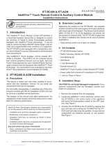
Figure 2.1 Good Faith Wall Surface Temperatures Above Appliance
B. Good Faith Wall Surface
NOTICE: Surface temperatures listed above are taken with
a temperature measuring probe as prescribed by the test
standard used for appliance certication. Temperatures
on walls or mantels taken with an infrared thermometer
may yield increased temperatures of up to 30 °F (17 °C) or
more depending on the thermometer settings and material
characteristics being measured. Use appropriate nishing
materials that are able to withstand these conditions. For
additional nishing guidelines, see Section 10.
Installation and service of this appliance should be performed by
qualied personnel. Hearth & Home Technologies recommends
HHT Factory Trained or NFI certied professionals.
MEASUREMENTS FROM
TOP EDGE OF THE OPENING
6 in.
18 in.
24 in.
30 in.
TO CEILING
12 in.
127°F
123°F
132°F
135°F
147°F
APPLIANCE FRONT
FIREPLACE
OPENING

Heat & Glo • SL-3X/5X/7X/9X-IFT (-G, -TG, -S) Installation Manual • 2633-980 Rev. J • 5/23
8
Figure 2.2 Good Faith TV Guidelines
Item Minimum Dimensions
A 2.5 inches
B 2 inches minimum to 3 inches
maximum
C 18 inches
D Wall Brkt + TV Thickness + 2.5
inches
BB
A
Appliance
TV
Mantel
A
C
Notes:
1. These are good faith recommended clearances only and not a guarantee of compliance with all TV
manufacturers’ maximum allowable operang temperatures.
2. Since every home has unique air flow characteriscs and maximum allowable operang temperatures
can vary from manufacturer to manufacturer and from model to model, actual TV temperatures should
be validated at the me of each installaon. TVs should not be used in situaons where the actual TV
temperature exceeds the manufacturers’ maximum allowable operang temperatures idenfied in the
TV’s technical specificaons. Contact the TV’s manufacturer directly if you cannot locate this
informaon or have quesons regarding the informaon.
3. Mantel height and depth must conform to mantle requirements specified in the appliance installaon
manual.
4. “C” dimension taken from the top of the hood or appliance opening.
5. Suggesons on how to further reduce TV temperatures:
a. Increase “A” dimension.
b. Increase “C” dimension, however, increasing “B” dimension beyond maximum recommended
typically results in higher temperatures.
TV Wall
Bracket
D
Appliance
C
TV on the wall TV recessed into the wall
Good Faith Guidelines for TV Installations Above Appliance

9
Heat & Glo • SL-3X/5X/7X/9X-IFT (-G, -TG, -S) Installation Manual • 2633-980 Rev. J • 5/23
D. Inspect Appliance and Components
WARNING! Risk of Fire or Explosion! Damaged parts
could impair safe operation. DO NOT install damaged, in-
complete or substitute components. Keep appliance dry.
WARNING! Risk of Fire, Explosion or Electric Shock!
DO NOT use this appliance if any part has been under
water. Call a qualied service technician to inspect the
appliance and to replace any part of the control system
and/or gas control which has been under water.
• Carefully remove the appliance and components from
the packaging.
• The vent system components and decorative barrier
fronts may be shipped in separate packages.
• If packaged separately, the log set and appliance grate
must be installed.
• Report to your dealer any parts damaged in shipment.
• This product is factory-equipped with an IntelliFire Touch®
remote control, which was paired to the appliance at the
factory. This specic remote control needs to remain with
the contents of the manual bag. Do not install batteries
in the remote control until performing the nal appliance
setup and checklist.
Hearth & Home Technologies disclaims any responsibility for,
and the warranty will be voided by, the following actions:
• Installation and use of any damaged appliance or vent
system component.
• Modication of the appliance or vent system.
• Installation other than as instructed by Hearth & Home
Technologies.
• Improper positioning of the logs/media (as applicable) or
the glass assembly.
• Installation and/or use of any component part not approved
by Hearth & Home Technologies.
C. Tools and Supplies Needed
Before beginning the installation be sure that the following
tools and building supplies are available.
Hand Tools Tape measure
Level Framing material
Manometer Framing square
Voltmeter Electric drill and bits (1/4 in.)
Plumb line Safety glasses/Gloves
Wrenches Reciprocating saw
1/4 in. nut driver
Non-corrosive leak check solution
1/2 - 3/4 in. length, #6 or #8 Self-drilling screws
1/4 in. length, #6 or #8 Self-drilling screws (B-Vent only)
Caulking material (300 ºF minimum continuous exposure
rating)

Heat & Glo • SL-3X/5X/7X/9X-IFT (-G, -TG, -S) Installation Manual • 2633-980 Rev. J • 5/23
10
3 3 Framing and Clearances
A. Appliance/Decorative Barrier Front Dimension Diagrams
Dimensions are actual appliance dimensions. Use for reference only. For framing dimensions and clearances refer to Section 5.
Figure 3.1 Appliance Dimensions
Appliance Dimensions Table
Q
R
Ø
O
P
L
M
N
GAS LINE ACCESS
T
S
C
V
A
B
U
E
D
F
ELECTRICAL
ACCESS
G
H
J
I
K
Ø
W
Ø
HEAT MANAGEMENT
SYSTEMS ACCESS
XX
Y
(C )
L
SL-3X-IFT SL-5X-IFT SL-7X-IFT SL-9X-IFT
Location Inches Millimeters Inches Millimeters Inches Millimeters Inches Millimeters
A 33 838 36 914 41 1041 48 1219
B 28-1/8 714 31-1/8 791 36-1/8 918 43 1092
C24-1/8 613 27-3/16 691 32-1/16 814 39-1/16 992
D 16 406 18-1/16 459 21-1/2 546 23-9/16 599
E 32-1/8 816 34-1/16 865 37-5/8 956 39-9/16 1005
F 3-1/2 89 3-1/2 89 3-1/2 89 3-1/2 89
G6-7/8 175 6-7/8 175 6-7/8 175 6-7/8 175
H 21-3/8 543 23-3/8 594 26-7/8 683 28-7/8 733
I32-3/8 822 34-3/8 873 37-7/8 962 39-7/8 1013
J34-1/2 876 36-7/16 926 39-15/16 1014 41-15/16 1065
K 8 203 8203 8203 8203
L8-3/4 222 8-3/4 222 8-3/4 222 8-3/4 222
M 16-1/4 413 16-1/4 413 16-1/4 413 16-1/4 413
N 1/2 13 1/2 13 1/2 13 1/2 13
O 22-3/4 578 25-3/4 654 30-3/4 781 37-3/4 959
P 11-3/8 289 12-7/8 327 15-3/8 391 18-7/8 479
Q15-7/8 403 15-7/8 403 15-7/8 403 15-7/8 403
R 6-5/8 168 6-5/8 168 6-5/8 168 6-5/8 168
S 2-1/8 54 2-1/8 54 2-1/8 54 2-1/8 54
T 6 152 6 152 6 152 6 152
U1 25 1 25 1 25 1 25
V28 711 30-1/16 764 33-9/16 853 35-9/16 903
W 5 127 5 127 5 127 5 127
X14 356 14 356 14 356 14 356
Y9-1/8 232 9-1/8 232 9-1/8 232 9-1/8 232

11
Heat & Glo • SL-3X/5X/7X/9X-IFT (-G, -TG, -S) Installation Manual • 2633-980 Rev. J • 5/23
FIRESCREEN DECORATIVE BARRIER FRONT
Figure 3.2 Decorative Barrier Front Dimensions - Firescreen
A B C D E F G
SL-3X-IFT FS-3
in. 26 23 28 1-5/8 2-5/8 25-1/16 26-3/4
mm 660 584 711 41 67 637 680
SL-5X-IFT FS-5 in. 28-7/8 25-1/8 31 1-5/8 2-5/8 27-1/8 28-3/4
mm 733 638 787 41 67 689 730
SL-7X-IFT FS-7 in. 34 28-3/4 35-15/16 1-5/8 2-5/8 30-5/8 32-1/4
mm 864 730 913 41 67 778 819
SL-9X-IFT FS-9 in, 40-7/8 30-5/8 43 1-5/8 2-5/8 32-5/8 34-1/4
mm 1038 778 1092 41 67 829 870
A
B
FG
ED
C
Barrier Mesh: Integral to
Decorative Barrier Front
Note: See Section 10 for hearth, mantel
and nishing requirements.
IMPORTANT! This replace requires an installed decorative barrier front to prevent direct contact with the hot
viewing glass. DO NOT operate the replace with the barrier removed.
Decorative barrier front must be ordered at time of replace purchase. If decorative barrier front is not present,
contact dealer.

Heat & Glo • SL-3X/5X/7X/9X-IFT (-G, -TG, -S) Installation Manual • 2633-980 Rev. J • 5/23
12
C
A
D
BE
F
G
Barrier Mesh: Integral to
Decorative Barrier Front
A B C D E F G
SL-5X-IFT CF-32 in. 26-9/16 18-11/16 30-13/16 23-5/16 25-7/16 3-1/2 4-9/16
mm 675 475 783 592 646 89 116
SL-7X-IFT CF-36 in. 31-1/2 22-3/16 35-13/16 26-13/16 28-15/16 3-1/2 4-9/16
mm 800 564 910 681 735 89 116
SL-9X-IFT CF-42 in. 38-1/2 24-1/16 42-3/4 28-11/16 30-13/16 3-1/2 4-9/16
mm 978 611 1086 729 783 89 116
CLEAN FACE DECORATIVE BARRIER FRONT
Note: See Section 10 for hearth, mantel
and nishing requirements.
Figure 3.3 Decorative Barrier Front Dimensions - Clean Face
IMPORTANT! This replace requires an installed decorative barrier front to prevent direct contact with the hot
viewing glass. DO NOT operate the replace with the barrier removed.
Decorative barrier front must be ordered at time of replace purchase. If decorative barrier front is not present,
contact dealer.

13
Heat & Glo • SL-3X/5X/7X/9X-IFT (-G, -TG, -S) Installation Manual • 2633-980 Rev. J • 5/23
Figure 3.4 Decorative Barrier Front Dimensions - Chateau
YB
A
C
D
E
F
X
Barrier Mesh: Integral to
Decorative Barrier Front
CHATEAU DECORATIVE BARRIER FRONT
1 IN. to 6 IN. Overlap
Fit Finishing-Refer to
Figure 10.10
A B C D E F X Y
SL-3X-IFT CHA-28 in. 24-7/16 16-1/8 29-1/16 1-1/8 5-13/16 27-5/16 29-3/8 28-3/4
mm 621 410 738 29 148 694 746 730
SL-5X-IFT CHA-32 in. 27-7/16 18-1/8 32-1/16 1-1/8 5-13/16 29-3/8 32-3/4 30-13/16
mm 697 460 814 29 148 746 832 783
SL-7X-IFT CHA-36 in. 32-7/16 20-1/2 37-3/16 1-1/8 7-7/8 32-7/8 37-3/8 34-3/8
mm 824 521 945 29 200 835 949 873
SL-9X-IFT CHA-42 in. 39-7/16 22-7/16 44-3/16 1-1/8 7-7/16 34-3/4 44-3/8 36-3/8
mm 1002 570 1122 29 189 883 1127 924
Note: See Section 10 for hearth, mantel
and nishing requirements.
IMPORTANT! This replace requires an installed decorative barrier front to prevent direct contact with the hot
viewing glass. DO NOT operate the replace with the barrier removed.
Decorative barrier front must be ordered at time of replace purchase. If decorative barrier front is not present,
contact dealer.

Heat & Glo • SL-3X/5X/7X/9X-IFT (-G, -TG, -S) Installation Manual • 2633-980 Rev. J • 5/23
14
Figure 3.5 Decorative Barrier Front Dimensions - Halston
HALSTON DECORATIVE BARRIER FRONT
C
A
F
B
E
D
X
Y
Barrier Mesh: Integral to
Decorative Barrier Front
1 IN. to 6 IN. Overlap
Fit Finishing-Refer to
Figure 10.10
A B C D E F X Y
SL-3X-IFT HAL-28 in. 24-7/16 16-1/8 29-1/16 1-1/8 5-13/16 27-5/16 29-3/8 28-3/4
mm 621 410 738 29 148 694 746 730
SL-5X-IFT HAL-32 in. 27-7/16 18-1/8 32-1/16 1-1/8 5-13/16 29-3/8 32-3/4 30-13/16
mm 697 460 814 29 148 746 832 783
SL-7X-IFT HAL-36 in. 32-7/16 21-1/4 37-3/16 1-1/8 6-1/4 32-7/8 37-3/8 34-3/8
mm 824 540 945 29 159 835 949 873
SL-9X-IFT HAL-42 in. 39-7/16 23-1/8 44-3/16 1-1/8 6-1/4 34-3/4 44-3/8 36-3/8
mm 1002 587 1122 29 159 883 1127 924
Note: See Section 10 for hearth, mantel
and nishing requirements.
IMPORTANT! This replace requires an installed decorative barrier front to prevent direct contact with the hot
viewing glass. DO NOT operate the replace with the barrier removed.
Decorative barrier front must be ordered at time of replace purchase. If decorative barrier front is not present,
contact dealer.

15
Heat & Glo • SL-3X/5X/7X/9X-IFT (-G, -TG, -S) Installation Manual • 2633-980 Rev. J • 5/23
CHATEAU FORGE DECORATIVE BARRIER FRONT
A
B
C
D
F
E
X
Y
Barrier Mesh: Integral to
Decorative Barrier Front
1 IN. to 6 IN. Overlap
Fit Finishing-Refer to
Figure 10.10
ABC D E F X Y
SL-5X-IFT CHAF-32 in. 27-1/8 17-1/8 32-5/16 1-1/8 7-1/2 29-7/16 32-3/4 30-13/16
mm 689 435 821 29 191 748 832 783
SL-7X-IFT CHAF-36 in. 32 20-3/4 37-1/8 1-3/16 7-9/16 32-7/8 37-3/8 34-3/8
mm 813 527 943 30 192 835 949 873
SL-9X-IFT CHAF-42 in. 39 22-5/8 44-3/16 1-1/8 7-5/8 34-3/4 44-3/8 36-3/8
mm 991 575 1122 29 194 883 1127 924
Note: See Section 10 for hearth, mantel
and nishing requirements.
Figure 3.6 Decorative Barrier Front Dimensions - Chateau Forge
IMPORTANT! This replace requires an installed decorative barrier front to prevent direct contact with the hot
viewing glass. DO NOT operate the replace with the barrier removed.
Decorative barrier front must be ordered at time of replace purchase. If decorative barrier front is not present,
contact dealer.

Heat & Glo • SL-3X/5X/7X/9X-IFT (-G, -TG, -S) Installation Manual • 2633-980 Rev. J • 5/23
16
Figure 3.7 Decorative Barrier Front Dimensions - Arcadia
A
B
C
D
E
F
Y
X
Barrier Mesh: Integral to
Decorative Barrier Front
1 IN. to 6 IN. Overlap
Fit Finishing-Refer to
Figure 10.10
ABC D E F X Y
SL-5X-IFT ARC-32
in. 27-7/16 16-7/8 32-1/4 1-1/8 6-1/2 29-3/8 32-3/4 30-13/16
mm 697 429 819 29 165 746 832 783
SL-7X-IFT ARC-36 in. 32-7/16 20-1/2 37-3/16 1-1/4 7-11/16 32-7/8 37-3/8 34-3/8
mm 824 521 945 32 195 835 949 873
SL-9X-IFT ARC-42 in. 39-7/16 22-7/16 44-3/16 1-1/4 7-7/16 34-3/4 44-3/8 36-3/8
mm 1002 570 1122 32 189 883 1127 924
ARCADIA DECORATIVE BARRIER FRONT
Note: See Section 10 for hearth, mantel
and nishing requirements.
IMPORTANT! This replace requires an installed decorative barrier front to prevent direct contact with the hot
viewing glass. DO NOT operate the replace with the barrier removed.
Decorative barrier front must be ordered at time of replace purchase. If decorative barrier front is not present,
contact dealer.

17
Heat & Glo • SL-3X/5X/7X/9X-IFT (-G, -TG, -S) Installation Manual • 2633-980 Rev. J • 5/23
Figure 3.8 Decorative Barrier Front Dimensions - Iron Age
IRON AGE DECORATIVE BARRIER FRONT
A
B
C
G
D
E
F
Barrier Mesh: Integral to
Decorative Barrier Front
1IN. to 6 IN. Overlap
Fit Finishing-Refer to
Figure 10.10
A B C D E F GXY
SL-7X-IFT FSI-36 in. 27-3/8 23-1/8 37-3/16 1-1/4 6-3/4 32-7/8 34-1/8 37-3/8 34-3/8
mm 695 587 945 32 172 835 867 949 873
SL-9X-IFT FSI-42 in. 34-3/8 25-3/16 44-3/16 1-1/4 6-3/4 34-13/16 36-1/16 44-3/8 36-3/8
mm 873 640 1122 32 172 884 916 1127 924
Note: See Section 10 for hearth, mantel
and nishing requirements.
IMPORTANT! This replace requires an installed decorative barrier front to prevent direct contact with the hot
viewing glass. DO NOT operate the replace with the barrier removed.
Decorative barrier front must be ordered at time of replace purchase. If decorative barrier front is not present,
contact dealer.

Heat & Glo • SL-3X/5X/7X/9X-IFT (-G, -TG, -S) Installation Manual • 2633-980 Rev. J • 5/23
18
B. Appliance Location and Clearances to
Combustibles
When selecting a location for the appliance it is important
to consider the required clearances to walls and allow suf-
cient clearance for heat management systems venting.
See Figure 3.9 and Figure 3.10.
WARNING! Risk of Fire or Burns! Provide adequate
clearance around air openings and for service access.
Due to high temperatures, the appliance should be lo-
cated out of trac and away from furniture and draperies.
NOTICE: Illustrations reect typical installations and are
FOR DESIGN PURPOSES ONLY. Illustrations/diagrams
are not drawn to scale. Actual installation may vary due to
individual design preference.
Figure 3.9 Appliance Locations
NOTICE: Allow 13 inches minimum clearance
on side(s) of appliance for venting of heat
management system.
13 IN. MIN.
Figure 3.10 Clearance for Heat Management System
J
C
A
K
H
B
F
D
I
IF
A
E
G
L
Refer to Section 10 for mantel and wall
projection information.
Consider the mantel or cabinet system to be
installed and comply with the necessary
requirements for elevated hearth. Refer to
instructions included with cabinet system.
Models A B C D E
Min. F G H I J K L
SL-3X-IFT
in. 39-1/2 34 55-7/8
See Section
10 for Mantel
Projections
1/2 44 62-1/4 16-1/4 48-1/2 68-3/4 13-1/2 7-1/2
mm 1003 864 1419 13 1118 1581 413 1232 1746 343 191
SL-5X-IFT
in. 42 37 59-1/2 1/2 44 62-1/4 16-1/4 48-1/2 68-3/4 15-1/16 7-1/2
mm 1067 940 1511 13 1118 1581 413 1232 1746 383 191
SL-7X-IFT
in. 45-1/2 42 64-3/8 1/2 45-1/2 64-3/8 16-1/4 48-1/2 68-3/4 16-5/8 7-1/2
mm 1156 1067 1635 13 1156 1635 413 1232 1746 422 191
SL-9X-IFT
in. 50-1/2 49 71-1/2 1/2 50-1/2 71-1/2 16-1/4 50-1/2 71-1/2 19-1/2 9-1/4
mm 1283 1245 1816 13 1283 1816 413 1283 1816 495 235
NOTICE: Additional clearances are required for heat management
systems installations. Provisions must be made in advance to ensure
t within the framing.

19
Heat & Glo • SL-3X/5X/7X/9X-IFT (-G, -TG, -S) Installation Manual • 2633-980 Rev. J • 5/23
E
H
I
F
G
J
MEASURE FROM TOP OF
UNIT OPENING OR FROM
TOP OF HOOD
Figure 3.11 Clearances to Combustibles
C
B
D
A
* MINIMUM FRAMING DIMENSIONS
Models
A B C D E F G H I J
DVP Pipe SLP Pipe
Rough
Opening
(Height)
**DVP Pipe SLP Pipe
Rough
Opening
(Width)
Clearance
to Room
Ceiling
***Combustible
Floor
****Minimum
Hearth
Required
Behind
Appliance
Sides of
Appliance
Front of
Appliance
Rough
Opening
(Width)
Rough
Opening
(Width)
Rough
Opening
(Depth)
Rough
Opening
(Depth)
SL-3X-IFT
in. 10 8-5/8 32-3/4 16-1/4 16-1/4 34 32 0 0 1/2 1/2 36
mm 254 219 832 413 413 864 813 0 0 13 13 914
SL-5X-IFT
in. 10 8-5/8 34-3/4 16-1/4 16-1/4 37 32 0 0 1/2 1/2 36
mm 254 219 882 413 413 940 813 0 0 13 13 914
SL-7X-IFT
in. 10 8-5/8 38-1/4 16-1/4 16-1/4 42 32 0 0 1/2 1/2 36
mm 254 219 972 413 413 1067 813 0 0 13 13 914
SL-9X-IFT
in. 10 8-5/8 40-1/4 16-1/4 16-1/4 49 32 0 0 1/2 1/2 36
mm 254 219 1022 413 413 1245 813 0 0 13 13 914
* Adjust framing dimensions for interior chase sheathing (such as sheetrock)
** Add 12 inches when rear venting with one 90º elbow.
*** When using combustible ooring materials, such as carpeting and padding, the combustible ooring material must not extend
higher than one inch from the base of the appliance when the appliance is mounted at oor level.
**** For installations with vinyl ooring see section 3.D.

Heat & Glo • SL-3X/5X/7X/9X-IFT (-G, -TG, -S) Installation Manual • 2633-980 Rev. J • 5/23
20
A chase is a vertical box-like structure built to enclose the
gas appliance and/or its vent system. In cooler climates
the vent should be enclosed inside the chase.
NOTICE: Treatment of ceiling restops and wall shield
restops and construction of the chase may vary with the
type of building. These instructions are not substitutes
for the requirements of local building codes. Therefore,
you MUST check local building codes to determine the
requirements to these steps.
NOTICE: Where required by code, install only sprinkler
heads with a sprinkler activation temperature classied
as Extra High.
• Sprinklers inside of chase: Keep sprinkler head away
from vent and chimney.
• Heat Management applications: Maintain 36 inches of
clearance to openings from which heat is discharged
such as convection slots, heat zone registers, etc. Refer
to Section 6.B for Heat Management options allowed
for this appliance.
Chases should be constructed and insulated in the same
manner as the thermal envelope of the home based on
the code requirements for that climate zone to prevent air
leakage and draft problems. The chase is an extension of
the building thermal envelope.
To further prevent drafts and air leakage, the wall shield
and ceiling restops should be sealed with caulk with
a minimum of 300 ºF continuous exposure rating to
seal gaps. Gas line holes and other openings should
be sealed with caulk with a minimum of 300 ºF continu-
ous exposure rating or stued with unfaced insulation. If the
appliance is being installed on a cement surface, a layer of
plywood may be placed underneath to prevent conducting
cold up into the room.
Minimum height requirements for an exterior chase on a top-
vented appliance are shown in Figure 3.12. Reference Fig-
ure 4.5 for additional clearances.
NOTICE: Install appliance on hard metal or wood surfaces
extending full width and depth. DO NOT install directly on
carpeting, vinyl, or any combustible material other than
wood.
WARNING! Risk of Fire! Maintain specied air space
clearances to appliance and vent pipe:
• Insulation and other materials must be secured to prevent
accidental contact.
• The chase must be properly blocked to prevent blown
insulation or other combustibles from entering and
making contact with replace or chimney.
• Failure to maintain airspace may cause overheating and
a re.
Figure 3.12 Exterior Chase - Minimum Height Requirements
C. Constructing the Appliance Chase
SL-3X = 40-13/16 IN.
SL-5X = 42-3/4 IN.
SL-7X = 46-1/4 IN.
SL-9X = 48-1/4 IN.
A
= REQUIRED MINIMUM OFF TOP = 0 IN.
3 IN. MIN. B*
* NOTE: If overhang “A” is less than 2
inches, clearance from top of termination
cap to bottom of overhang “B” MUST be a
minimum of 4 inches. If A is two inches
or greater, see Figure 4.4.
/