Makita DFR750 User manual

Category
Power tools
Type
User manual

Makita DFR750 is a cordless auto feed screwdriver designed for driving screws into wood, metal, and plastic. It features a screw length adjustment mechanism with 7 positive-lock settings, allowing for precise control over the driving depth. The tool also has a reversing switch for changing the direction of rotation and a built-in protection system to prevent overloading and overheating.

Makita DFR750 is a cordless auto feed screwdriver designed for driving screws into wood, metal, and plastic. It features a screw length adjustment mechanism with 7 positive-lock settings, allowing for precise control over the driving depth. The tool also has a reversing switch for changing the direction of rotation and a built-in protection system to prevent overloading and overheating.

008261
GB Cordless Auto Feed Instruction manual
Screwdriver
F
Visseuse Automatique sans Fil
Manuel d’instructions
D Akku-Schnellbau-Magazin- Betriebsanleitung
Schrauber
I Avvitatore a batteria con Istruzioni per l’uso
alimentatore automatico
NL Accuschroefautomaat Gebruiksaanwijzing
E Atornillador Autoalimentado Manual de instrucciones
Inalámbrico
P Parafusadeira de Manual de instruções
Autoalimentação a Bateria
DK Ledningsfri skruetrækker med Brugsanvisning
automatisk fremføring
GR Φορητό αυτοτροφοδοτούμενο Οδηγίες χρήσης
κατσαβίδι
DFR540
DFR550
DFR750
Downloaded from www.Manualslib.com manuals search engine
2
1012156 2012128
3008123 4008124
5008282 6008283
7008285 8008286
1
2
3
4
5
67
8
6
9
10
5 mm
A
B
11
AB
12
9
13
14
15
16
Downloaded from www.Manualslib.com manuals search engine
3
9008290 10 008288
11 008281 12 008128
13 008289 14 008262
15 008263 16 006812
20
21
1
1
2
22
15 mm
23 6
Downloaded from www.Manualslib.com manuals search engine
4
17 006258 18 008285
19 008287 20 006816
21 006817 22 006304
24
9
13
25
26
27
28 29
30
31
30
Downloaded from www.Manualslib.com manuals search engine
5
ENGLISH (Original Instructions)
Explanation of general view
SPECIFICATIONS
Due to our continuing program of research and development, the specifications herein are subject to change without
notice.
Specifications and battery cartridge may differ from country to country.
Weight, with battery cartridge, according to EPTA-Procedure 01/2003
Intended use ENE033-1
The tool is intended for screw driving in wood, metal and
plastic.
General Power Tool Safety
Warnings GEA010-1
WARNING Read all safety warnings and all
instructions. Failure to follow the warnings and
instructions may result in electric shock, fire and/or
serious injury.
Save all warnings and
instructions for future reference.
CORDLESS SCREWDRIVER
SAFETY WARNINGS GEB050-2
1. Hold power tool by insulated gripping surfaces,
when performing an operation where the fastener
may contact hidden wiring. Fasteners contacting a
“live” wire may make exposed metal parts of the
power tool “live” and could give the operator an
electric shock.
2. Always be sure you have a firm footing. Be sure
no one is below when using the tool in high
locations.
3. Hold the tool firmly.
4. Keep hands away from rotating parts.
5. Do not touch the bit or the workpiece immediately
after operation; they may be extremely hot and
could burn your skin.
SAVE THESE INSTRUCTIONS.
WARNING:
DO NOT let comfort or familiarity with product (gained
from repeated use) replace strict adherence to safety
rules for the subject product. MISUSE or failure to
follow the safety rules stated in this instruction
manual may cause serious personal injury.
IMPORTANT SAFETY
INSTRUCTIONS ENC007-7
FOR BATTERY CARTRIDGE
1. Before using battery cartridge, read all
instructions and cautionary markings on (1)
battery charger, (2) battery, and (3) product using
battery.
2. Do not disassemble battery cartridge.
3. If operating time has become excessively shorter,
stop operating immediately. It may result in a risk
of overheating, possible burns and even an
explosion.
4. If electrolyte gets into your eyes, rinse them out
with clear water and seek medical attention right
away. It may result in loss of your eyesight.
5. Do not short the battery cartridge:
(1) Do not touch the terminals with any
conductive material.
(2) Avoid storing battery cartridge in a container
with other metal objects such as nails, coins,
etc.
1. Red indicator
2. Button
3. Battery cartridge
4. Star marking
5. Lever
6. Stopper base
7. Label on feeder box
8. Fenestella
9. Casing
10. Adjusting knob
11. Switch trigger
12. Reversing switch lever
13. Thumb screw
14. Plane bearing
15. Dust cover
16. Bit
17. Feeder box
18. Screw strip
19. Screw guide
20. Driving position
21. Reverse button
22. Hook
23. Wall
24. Limit mark
25. Front cover
26. Screws
27. Spring
28. Arm
29. Recessed part
30. Carbon brush cap
31. Hole
Model DFR540 DFR550 DFR750
Screw strip 4 x 25 - 55 mm 4 x 45 - 75 mm
No load speed (min-1) 4,000
Overall length 424 m 464 mm
Net weight 2.0 kg 2.1 kg 2.1 kg
Rated voltage D.C. 14.4 V D.C. 18 V D.C. 18 V
Downloaded from www.Manualslib.com manuals search engine
6
(3) Do not expose battery cartridge to water or
rain.
A battery short can cause a large current flow,
overheating, possible burns and even a
breakdown.
6. Do not store the tool and battery cartridge in
locations where the temperature may reach or
exceed 50°C (122°F).
7. Do not incinerate the battery cartridge even if it is
severely damaged or is completely worn out. The
battery cartridge can explode in a fire.
8. Be careful not to drop or strike battery.
9. Do not use a damaged battery.
SAVE THESE INSTRUCTIONS.
Tips for maintaining maximum battery life
1. Charge the battery cartridge before completely
discharged.
Always stop tool operation and charge the battery
cartridge when you notice less tool power.
2. Never recharge a fully charged battery cartridge.
Overcharging shortens the battery service life.
3. Charge the battery cartridge with room
temperature at 10°C - 40°C (50°F - 104°F). Let a hot
battery cartridge cool down before charging it.
4. Charge the battery cartridge once in every six
months if you do not use it for a long period of
time.
FUNCTIONAL DESCRIPTION
CAUTION:
Always be sure that the tool is switched off and the
battery cartridge is removed before adjusting or
checking function on the tool.
Installing or removing battery cartridge
(Fig. 1)
Always switch off the tool before installing or removing
of the battery cartridge.
To remove the battery cartridge, slide it from the tool
while sliding the button on the front of the cartridge.
To install the battery cartridge, align the tongue on the
battery cartridge with the groove in the housing and slip
it into place. Always insert it all the way until it locks in
place with a little click. If you can see the red indicator
on the upper side of the button, it is not locked
completely. Install it fully until the red indicator cannot
be seen. If not, it may accidentally fall out of the tool,
causing injury to you or someone around you.
Do not use force when installing the battery cartridge. If
the cartridge does not slide in easily, it is not being
inserted correctly.
Battery protection system (Lithium-ion
battery with star marking) (Fig. 2)
Lithium-ion batteries with a star marking are equipped
with a protection system. This system automatically cuts
off power to the tool to extend battery life.
The tool will automatically stop during operation if the tool
and/or battery are placed under one of the following
conditions:
• Overloaded:
The tool is operated in a manner that causes it to
draw an abnormally high current.
In this situation, release the trigger switch on the tool
and stop the application that caused the tool to
become overloaded. Then pull the trigger switch
again to restart.
If the tool does not start, the battery is overheated. In
this situation, let the battery cool before pulling the
trigger switch again.
Low battery voltage:
The remaining battery capacity is too low and the tool
will not operate. In this situation, remove and
recharge the battery.
Setting for desired screw length (Fig. 3)
There are 7 positive-lock screw length settings. To obtain
the desired setting, pull out the stopper base while
depressing the lever until you see the number of the
desired screw length (indicated on the label on feeder
box) appear to rest in the fenestella of stopper base. See
the table below for the relation between the number
indicated on the label on feeder box and the respective
screw length.
For Models DFR540, DFR550
008238
For Model DFR750
008241
Adjusting the driving depth (Fig. 4)
Depress the stopper base as far as it will go. While
keeping it in this position, turn the adjusting knob until the
bit tip projects approx. 5 mm from the stopper base. Drive
a trial screw. If the screw head projects above the surface
of the workpiece, turn the adjusting knob in the “A”
direction; if the screw head is counter-sunk, turn the
adjusting knob in the “B” direction.
Number indicated on the label Screw length
25 25 mm
30 30 mm
35 35 mm
40 40 mm
45 45 mm
50 50 mm
55 55 mm
Number indicated on the label Screw length
45 45 mm
50 50 mm
55 55 mm
60 60 mm
65 65 mm
70 70 mm
75 75 mm
Downloaded from www.Manualslib.com manuals search engine
7
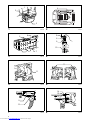
Switch action (Fig. 5)
CAUTION:
Before inserting the battery cartridge into the tool,
always check to see that the switch trigger actuates
properly and returns to the “OFF” position when
released.
To start the tool, simply pull the switch trigger. Release
the switch trigger to stop.
Reversing switch action (Fig. 6)
This tool has a reversing switch to change the direction of
rotation. Depress the reversing switch lever from the A
side for clockwise rotation or from the B side for
counterclockwise rotation.
When the reversing switch lever is in the neutral position,
the switch trigger cannot be pulled.
CAUTION:
Always check the direction of rotation before operation.
Use the reversing switch only after the tool comes to a
complete stop. Changing the direction of rotation
before the tool stops may damage the tool.
When not operating the tool, always set the reversing
switch lever to the neutral position.
ASSEMBLY
CAUTION:
Always be sure that the tool is switched off and the
battery cartridge is removed before carrying out any
work on the tool.
Installing or removing the bit
Loosen the thumb screws which secure the casing. Pull
out the casing in the direction of the arrow. (Fig. 7)
Press the dust cover toward the plane bearing and pull
out the bit. If the dust cover cannot be moved as far as the
plane bearing, try it again after turning the bit slightly. To
install the bit, insert it into the socket while turning it
slightly. After installing, always make sure that the bit is
securely held in place by trying to pull it out. (Fig. 8)
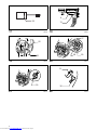
Installing screw strip
Insert the screw strip through the screw guide. Then insert
it through the feeder box until the first screw reaches the
position next to the driving position. (Fig. 9 & 10)
Removing screw strip
To remove the screw strip, just pull it out in the direction of
the arrow. If you depress the reverse button, you can pull
out the screw strip in the reverse direction of the arrow.
(Fig. 11 & 12)
Folding screw guide (Fig. 13)
Screw guide is foldable. Folding the screw guide allows
space used for storage to be minimal.
Carry hook
The carry hook is convenient for temporarily hooking the
tool. It can be installed on either side of the tool. When
removing the carry hook, widen it by pressing its right
ends ON BOTH SIDES in the directions of arrow (1) and
raise it in the direction of the arrow (2). (Fig. 14)
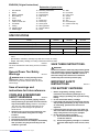
OPERATION
Driving operation (Fig. 15)
Switch on the tool by pulling the switch trigger. Hold the
tool squarely and firmly up against the driving surface. A
screw will be automatically carried to the driving position
and fastened.
CAUTION:
Always check the bit carefully for wear before driving
operations. Replace a worn bit or poor fastening may
result.
Always hold the tool squarely against the driving
surface. Holding it at an angle may damage the screw
heads and cause wear on the bit. This may also lead to
poor fastening.
Always keep the tool firmly against the driving surface
until the driving is over. Failure to do so may cause
insufficient fastening of screws.
Be careful not to drive a screw onto another screw
already fastened.
Do not operate the tool without screws. It will damage
the driving surface.
Do not apply oil or grease on the sliding surface of the
feeder box.
Driving in corner (Fig. 16)
This tool can be used to drive at a position 15 mm away
from the wall as shown in the figure.
CAUTION:
Driving at a position closer than 15 mm to the wall or
driving with the stopper base in contact with the wall
may damage the screw heads and cause wear on the
bit. This may also lead to poor fastening of screws and
malfunction of the tool.
MAINTENANCE
CAUTION:
Always be sure that the tool is switched off and the
battery cartridge is removed before attempting to
perform inspection or maintenance.
Never use gasoline, benzine, thinner, alcohol or the
like. Discoloration, deformation or cracks may result.
Replacing carbon brushes (Fig. 17)
Replace when they wear down to the limit mark. Keep the
carbon brushes clean and free to slip in the holders.
Both carbon brushes should be replaced at the same
time. Use only identical carbon brushes.
Loosen the thumb screws which secure the casing. Pull
out the casing in the direction of the arrow. (Fig. 18)
Use a screwdriver to remove two screws then remove the
front cover. (Fig. 19)
Raise the arm part of the spring and then place it in the
recessed part of the housing with a slotted bit screwdriver
of slender shaft or the like. (Fig. 20)
Use pliers to remove the carbon brush caps of the carbon
brushes. Take out the worn carbon brushes, insert the
new ones and replace the carbon brush caps in reverse.
(Fig. 21)
Make sure that the carbon brush caps have fit into the
holes in brush holders securely. (Fig. 22)
Reinstall the front cover and tighten two screws securely.
Downloaded from www.Manualslib.com manuals search engine
8
To maintain product SAFETY and RELIABILITY, repairs,
any other maintenance or adjustment should be
performed by Makita Authorized Service Centers, always
using Makita replacement parts.
OPTIONAL ACCESSORIES
CAUTION:
These accessories or attachments are recommended
for use with your Makita tool specified in this manual.
The use of any other accessories or attachments might
present a risk of injury to persons. Only use accessory
or attachment for its stated purpose.
If you need any assistance for more details regarding
these accessories, ask your local Makita Service Center.
Drywall screw strip
Phillips bit
Various type of Makita genuine batteries and chargers
Plastic carrying case
NOTE:
Some items in the list may be included in the tool
package as standard accessories. They may differ
from country to country.
Noise ENG905-1
The typical A-weighted noise level determined according
to EN60745:
Model DFR540
Sound pressure level (LpA): 77 dB (A)
Uncertainty (K): 3 dB (A)
The noise level under working may exceed 80 dB (A).
Model DFR550
Sound pressure level (LpA): 78 dB (A)
Uncertainty (K): 3 dB (A)
The noise level under working may exceed 80 dB (A).
Model DFR750
Sound pressure level (LpA): 76 dB (A)
Uncertainty (K): 3 dB (A)
The noise level under working may exceed 80 dB (A).
Wear ear protection.
Vibration ENG900-1
The vibration total value (tri-axial vector sum) determined
according to EN60745:
Work mode: screwdriving without impact
Vibration emission (ah): 2.5 m/s2 or less
Uncertainty (K): 1.5 m/s2
ENG901-1
The declared vibration emission value has been
measured in accordance with the standard test method
and may be used for comparing one tool with another.
The declared vibration emission value may also be
used in a preliminary assessment of exposure.
WARNING:
The vibration emission during actual use of the power
tool can differ from the declared emission value
depending on the ways in which the tool is used.
Be sure to identify safety measures to protect the
operator that are based on an estimation of exposure in
the actual conditions of use (taking account of all parts
of the operating cycle such as the times when the tool
is switched off and when it is running idle in addition to
the trigger time).
For European countries only ENH101-15
EC Declaration of Conformity
We Makita Corporation as the responsible
manufacturer declare that the following Makita
machine(s):
Designation of Machine: Cordless Auto Feed Screwdriver
Model No./ Type: DFR540, DFR550, DFR750
are of series production and
Conforms to the following European Directives:
2006/42/EC
And are manufactured in accordance with the following
standards or standardised documents:
EN60745
The technical documentation is kept by our authorised
representative in Europe who is:
Makita International Europe Ltd.,
Michigan Drive, Tongwell,
Milton Keynes, Bucks MK15 8JD, England
30. 1. 2009
Tomoyasu Kato
Director
Makita Corporation
3-11-8, Sumiyoshi-cho,
Anjo, Aichi, 446-8502, JAPAN
Downloaded from www.Manualslib.com manuals search engine
  • Page 1 1
  • Page 2 2
  • Page 3 3
  • Page 4 4
  • Page 5 5
  • Page 6 6
  • Page 7 7
  • Page 8 8

Makita DFR750 User manual

Category
Power tools
Type
User manual

Makita DFR750 is a cordless auto feed screwdriver designed for driving screws into wood, metal, and plastic. It features a screw length adjustment mechanism with 7 positive-lock settings, allowing for precise control over the driving depth. The tool also has a reversing switch for changing the direction of rotation and a built-in protection system to prevent overloading and overheating.

Ask a question and I''ll find the answer in the document

Finding information in a document is now easier with AI