Page is loading ...

WARNING: If the information in this manual is not fol-
lowed exactly, a re or explosion may result causing
property damage, personal injury or loss of life.
Carefully review the instructions supplied with the
decorative type unvented room heater for the minimum
replace size requirement.
Do not install an appliance in this rebox unless this
rebox meets the minimum dimensions required for
the installation.
This rebox has been tested and approved by CSA
under ANSI Z21.91 for use with any ANSI Z21.11.2 ap-
proved gas logs.
This appliance may be installed in an aftermarket*, per-
manently located, manufactured (mobile) home, where
not prohibited by local codes.
This appliance is only for use with the type of gas indi-
cated on the rating plate. This appliance is not convert-
ible for use with other gases.
*Aftermarket: Completion of sale, not for purpose of resale, from the manufacturer
INSTALLER: Leave this manual with the appliance.
CONSUMER: Retain this manual for future reference.
For more information, visit www.desatech.com
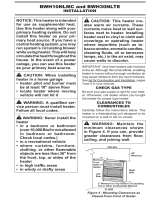
UNVENTED (VENT-FREE) UNIVERSAL FIREBOX
SAFETY INFORMATION AND INSTALLATION MANUAL
Shown with optional
cabinet mantel, hearth
base.
HDFB32C
CIRCULATING LOUVERED MODEL

www.desatech.com
113900-01D2
WARNING: Improper
installation, adjustment,
alteration, service or
maintenance can cause
injury or property dam-
age. Refer to this manual
for correct installation
and operational proce-
dures. For assistance or
additional information
consult a qualified in-
staller, service agency or
the gas supplier.
WARNING: For use
only with a listed gas-
fired unvented decora-
tive room heater. Not to
exceed 40,000 Btu/Hr. Do
not build a wood re.
IMPORTANT: Read this owner’s
manual carefully and completely
before trying to assemble, op-
erate or service this rebox.
Improper use of this rebox can
cause serious injury or death
from burns, re, explosion, elec-
trical shock or carbon monoxide
poisoning.
WARNING: Any change to
this rebox or its controls can
be dangerous.
WARNING: Do not use a blow-
er insert, hood, heat exchanger
insert or other accessory not ap-
proved for use with this heater.
WARNING: Do not allow fans
to blow directly into the rebox.
Avoid any drafts that alter burner
ame patterns. Ceiling fans can
create drafts that alter burner
ame patterns. Altered burner
patterns can cause sooting.
Due to high temperatures, the
rebox should be located out of
trafc and away from furniture
and draperies.
Do not place clothing or other
ammable material on or near
rebox. Never place any objects
on the rebox or logs.
Firebox front and screen be-
come very hot when running
firebox. Keep children and
adults away from hot surfaces to
avoid burns or clothing ignition.
Firebox will remain hot for a time
after shutdown. Allow surfaces
to cool before touching.
Carefully supervise young chil-
dren when they are in the room
with rebox.
SAFETY INFORMATION
TABLE OF CONTENTS
Safety Information ............................................... 2
Local Codes......................................................... 3
Unpacking............................................................ 3
Product Features ................................................. 4
Locating Firebox ................................................. 4
Air For Combustion and Ventilation ..................... 4
Installation ........................................................... 7
Technical Service............................................... 13
Replacement Parts ............................................ 13
Accessories ....................................................... 14
Parts Centrals .................................................... 15
Illustrated Parts Breakdown and Parts List........ 16
Warranty Information ...........................Back Cover

www.desatech.com
113900-01D 3
You must operate this replace
with the provided replace screen
(closed), hood and brick liner in
place. Make sure these parts are
in place before running rebox.
Keep the rebox area clear and
free from combustible materials,
gasoline and other ammable
vapors and liquids.
1. This rebox shall not be installed in a
bedroom or bathroom.
2. Neverinstalltherebox
• in a recreational vehicle
• where curtains, furniture, clothing or
other ammable objects are less than
36" from the front and 42" from the top.
For side clearances see Figure 6 on
page 8
•inhightrafcareas
• in windy or drafty areas
3. Donotusethisreboxasawood-burning
replace.Useonly decorativeunvented
room heaters (log sets).
4. Do not add extra logs or ornaments such as
pine cones, vermiculite or rock wool. Using
these added items can cause sooting.
5. Vent-free gas log heaters installed in these
reboxes require freshair ventilationto
run properly. See Air for Combustion and
Ventilation, page 4.
6. Donotrunrebox
•whereammableliquidsorvaporsare
used or stored
• under dusty conditions
7. Do notuse thisrebox to cookfood or
burnpaperorotherobjects.
8. Turnreboxoffandletcoolbeforeservic-
ing.Onlyaqualiedservicepersonshould
serviceandrepairrebox.
9. Operatingvent-freelogsetsinarebox
above elevations of 4,500 feet could
cause pilot outage.
10.Donotusethereboxifithasbeenun-
der water due to the shock hazard that
could result with the blower accessary (if
installed) in place.
11.Provideadequateclearancesaroundair
openings.
SAFETY INFORMATION
Continued
LOCAL CODES
Installandusereplacewithcare.Followall
local codes. In the absence of local codes,
use the latest edition of The National Fuel Gas
Code ANSI Z223.1/NFPA 54*. Firebox must
be electrically grounded in accordance with
the National Electrical Code, ANSI/NFPA70
(latest edition).
*Available from:
American National Standards Institute, Inc.
1430 Broadway
New York, NY 10018
National Fire Protection Association, Inc.
Batterymarch Park
Quincy, MA 02269
State of Massachusetts: The installa-
tion must be made by a licensed plumber
or gas tter in the Commonwealth of
Massachusetts.
Sellers of unvented propane or natural
gas-red supplemental room heaters
shall provide to each purchaser a copy of
527 CMR 30 upon sale of the unit.
Vent-free gas products are prohibited for
bedroom and bathroom installation in
the Commonwealth of Massachusetts.
UNPACKING
1. With utility knife, cut the carton all the way
around above the staples on the bottom
tray.Liftthecartonofftherebox.Remove
packing.
2. Check carton contents for the following:
• Screen assembly
• Screen support rod
• Hardware and parts bag containing the
following:
Owner’s Operation and Installation
Manual
Black #10 x 3/8" Phillips screws
3. If any items are missing, inform dealer
whereyouboughttherebox.
4. Check all items for any shipping damage.
If damaged, promptly inform dealer where
youboughtrebox.

www.desatech.com
113900-01D4
22
1
/
2
"
16
11
/
16
"
13
1
/
4
"
*
14
1
/
4
"
31
5
/
8
"
34
3
/
8
"
35
5
/
8
"
19
1
/
4
"
Figure 3 - Firebox Top View
*Note: 14
1
/
4
"istotalreboxcavitydepthincluding
brick liner. 13
1
/
4
" is depth of at oor including
brick liner.
LOCATING FIREBOX
Planwhereyouwillinstalltherebox.Thiswill
save time and money later when you install
therebox.Beforeinstallation,considerthe
following:
1. Wherethereboxwillbelocated.Allowfor
wall and ceiling clearances (see Installa-
tion Clearances, page 8).
2. Everything needed to complete installa-
tion.
3. These models CANNOT be installed in a
bedroom or bathroom.
4. Proper air for combustion and ventilation
(see Air For Combustion and Ventila-
tion).
AIR FOR COMBUSTION
AND VENTILATION
WARNING: This rebox shall
not be installed in a conned
space or unusually tight construc-
tion unless provisions are provid-
ed for adequate combustion and
ventilation air. Read the following
instructions to insure proper fresh
air for this and other fuel-burning
appliances in your home.
Today’shomesarebuiltmoreenergyefcient
than ever. New materials, increased insulation
and new construction methods help reduce
heat loss in homes. Home owners weather
strip and caulk around windows and doors
to keep the cold air out and the warm air in.
During heating months, home owners want
their homes as airtight as possible.
12
1
/
2
"
9
3
/
4
"
4
5
/
8
"
2
1
/
2
"
6"
32
3
/
16
"
2
1
/
4
"
Electrical Access Hole
Gas Line Access
Figure 2 - Firebox Side View
35
1
/
16
"
31
3
/
4
"
1
1
/
4
"
16
1
/
4
"
2
3
/
4
"
3
7
/
8
"
6
3
/
4
"
2
3
/
4
"
6
3
/
8
"
19
3
/
8
"
1
1
/
4
"
Built-in Nailing Flanges
Figure 1 - Firebox Front View
PRODUCT FEATURES
OPERATION
Thisreboxisdesignedtoacceptunvented
decorativegaslogs.Itrequiresnooutsidevent-
ing or chimney making installation easy and
inexpensive. When used without the blower
the rebox requires no electricity making it
ideal for emergency backup heat.
BLOWER ACCESSORY
Thisreboxhasanelectricblower.Thevari-
able blower allows you to select the fan speed
you desire. The blower circulates heated air
fromthereboxintotheroom.Useofblower
is optional.

www.desatech.com
113900-01D 5
While it is good to make your home energy
efcient,yourhomeneedstobreathe.Fresh
air must enter your home. All fuel-burning ap-
pliances need fresh air for proper combustion
and ventilation.
Exhaustfans,reboxes,clothesdryersandfuel
burning appliances draw air from the house to
operate.Youmustprovideadequatefreshair
for these appliances. This will insure proper
venting of vented fuel-burning appliances.
PROVIDING ADEQUATE
VENTILATION
The following are excerpts from National Fuel
Gas Code ANSI Z223.1/NFPA 54, Section 5.3,
Air for Combustion and Ventilation.
All spaces in homes fall into one of the three
followingventilationclassications:
1. Unusually Tight Construction
2.UnconnedSpace
3.ConnedSpace
The information on pages 4 through 6 will help
youclassifyyourspaceandprovideadequate
ventilation.
Unusually Tight Construction
The air that leaks around doors and windows
may provide enough fresh air for combus-
tion and ventilation. However, in buildings of
unusually tight construction, you must provide
additional fresh air.
Unusually tight construction is dened as
construction where:
a. walls and ceilings exposed to the out-
side atmosphere have a continuous
water vapor retarder with a rating of
one perm (6x10
-11
kg per pa-sec-m
2
) or
less with openings gasketed or sealed
and
b. weather stripping has been added on
openable windows and doors and
c. caulking or sealants are applied to
areas such as joints around window
and door frames, between sole plates
and oors, between wall-ceiling joints,
between wall panels, at penetrations
for plumbing, electrical and gas lines
and at other openings.
AIR FOR COMBUSTION
AND VENTILATION
Continued
If your home meets all of the three criteria
above, you must provide additional fresh
air. See Ventilation Air From Outdoors,
page 6.
If your home does not meet all of the
three
criteria above, proceed to Determining
Fresh-Air Flow For Firebox Location.
Conned Space and Unconned Space
The National Fuel Gas Code ANSI Z223.1/
NFPA 54denesaconnedspaceasaspace
whose volume is less than 50 cubic feet per
1,000 Btu per hour (4.8 m3 per kw) of the ag-
gregate input rating of all appliances installed
inthatspaceandanunconnedspaceasa
space whose volume is not less than 50 cubic
feet per 1,000 Btu per hour (4.8 m3 per kw)
of the aggregate input rating of all appliances
installed in that space. Rooms communicating
directly with the space in which the appliances
are installed*, through openings not furnished
with doors, are considered a part of the un-
connedspace.
*Adjoiningroomsarecommunicatingonlyif
there are doorless passageways or ventilation
grills between them.
DETERMINING FRESH-AIR FLOW
FOR HEATER LOCATION
Determining if You Have a Conned or
Unconned Space
Use this work sheet to determine if you have
aconnedorunconnedspace.
Space: Includes the room in which you will
installheaterplusanyadjoiningroomswith
doorless passageways or ventilation grills
between the rooms.
1. Determine the volume of the space (length
x width x height).
Length x Width x Height =__________cu. ft.
(volume of space)
Example: Space size 20 ft. (length) x 16 ft.
(width) x 8 ft. (ceiling height) = 2560 cu. ft.
(volume of space)
If additional ventilation to adjoining room
is supplied with grills or openings, add the
volume of these rooms to the total volume
of the space.
2. Multiply the space volume by 20 to determine
the maximum Btu/Hr the space can support.
________ (volume of space) x 20 = (Maxi-
mum Btu/Hr the space can support)
Example: 2560 cu. ft. (volume of space) x 20
= 51,200 (maximum Btu/Hr the space can
support)

www.desatech.com
113900-01D6
AIR FOR COMBUSTION
AND VENTILATION
Continued
WARNING: If the area in
which the rebox and gas log
heater may be operated is
smaller than that dened as
an unconned space or if the
building is of unusually tight
construction, provide adequate
combustion and ventilation air
by one of the methods described
in the National Fuel Gas Code,
ANSI Z223.1/NFPA 54 Section 5.3
or applicable local codes.
VENTILATION AIR
Ventilation Air From Inside Building
This fresh air would come from an adjoin-
ing unconned space. When ventilating to
an adjoining unconned space, you must
provide two permanent openings: one within
12" of the ceiling and one within 12" of the
ooronthewallconnectingthetwospaces
(see options 1 and 2, Figure 4). You can also
removedoorintoadjoiningroom(seeoption
3, Figure 4). Follow the National Fuel Gas
Code ANSI Z223.1/NFPA 54, Section 5.3, Air
for Combustion and Ventilationfor required
size of ventilation grills or ducts.
Figure 4 - Ventilation Air from Inside
Building
Or
Remove
Door into
Adjoining
Room,
Option
3
Ventilation Grills
Into Adjoining Room,
Option 2
Ventilation
Grills
Into Adjoining
Room,
Option 1
12"
12"
3. Add the Btu/Hr of all fuel burning appliances
in the space.
Vent-free heater __________ Btu/Hr
Gas water heater* __________ Btu/Hr
Gas furnace __________ Btu/Hr
Vented gas heater __________ Btu/Hr
Gasreplacelogs __________ Btu/Hr
Other gas appliances* + ________ Btu/Hr
Total = ________ Btu/Hr
* Do not include direct-vent gas appliances.
Direct-vent draws combustion air from the
outdoors and vents to the outdoors.
Example:
Gas water heater _________ Btu/Hr
Vent-freereplace + ________ Btu/Hr
Total = ________ Btu/Hr
4. Compare the maximum Btu/Hr the space
can support with the actual amount of Btu/Hr
used.
_______ Btu/Hr (maximum the space can
support)
_______ Btu/Hr (actual amount of Btu/Hr
used)
Example: 51,200 Btu/Hr (maximum the
space can support)
79,000 Btu/Hr (actual amount of
Btu/Hr used)
Thespaceintheaboveexampleisaconned
space because the actual Btu/Hr used is more
than the maximum Btu/Hr the space can sup-
port. You must provide additional fresh air. Your
options are as follows:
A.
Rework worksheet, adding the space of an
adjoiningroom.Iftheextraspaceprovides
anunconnedspace,removedoortoadjoin-
ing room or add ventilation grills between
rooms. See Ventilation Air From Inside
Building below.
B. Vent room directly to the outdoors. See
Ventilation Air From Outdoors.
C. Install a lower Btu/Hr heater, if lower
Btu/Hrsizemakesroomunconned.
If the actual Btu/Hr used is less than the
maximum Btu/Hr the space can support, the
spaceisanunconnedspace.Youwillneed
no additional fresh air ventilation.
40,000
39,000
79,000

www.desatech.com
113900-01D 7
WARNING: Never install the
rebox
• in a bedroom or bathroom
• in a recreational vehicle
• where curtains, furniture,
clothing or other ammable
objects are less than 36" from
the front and 42" from the top
of rebox - for side clearances
see Figure 6, page 8
• in high trafc areas
IMPORTANT: Vent-free gas log heaters add
moisturetotheair.Althoughthisisbenecial,
installing rebox in rooms without enough
ventilation air may cause mildew to form from
too much moisture. See Air for Combustion
and Ventilation, page 4.
IMPORTANT:Makesurethereboxislevel.
If rebox is not level, log set will not work
properly.
Note:Yourreboxisdesignedtobeusedin
zero clearance installations. Wall or framing
material can be placed directly against any
exterior surface on the rear, sides or top of
yourrebox,exceptwherestandoffspacers
are integrally attached. If standoff spacers
areattached toyourrebox, thesespacers
can be placed directly against wall or fram-
ing materials.
Use the dimensions shown for rough openings
to create the easiest installation (see Built-In
Firebox Installation, page 12).
Ventilation Air From Outdoors
Provide extra fresh air by using ventilation
grills or ducts. You must provide two perma-
nent openings: one within 12" of the ceiling
andonewithin12"oftheoor.Connectthese
items directly to the outdoors or spaces open
to the outdoors. These spaces include attics
and crawl spaces. Follow the National Fuel
Gas Code ANSI Z223.1/NFPA 54, Section 5.3,
Air for Combustion and Ventilationforrequired
size of ventilation grills or ducts.
IMPORTANT: Do not provide openings for
inlet or outlet air into attic if attic has a thermo-
stat-controlled power vent. Heated air entering
the attic will activate the power vent.
Figure 5 - Ventilation Air from Outdoors
Outlet
Air
Ventilated
Attic
Outlet
A
ir
Inlet
Air
Inlet Air
Ventilated
Crawl Space
To
Crawl
Space
To Attic
INSTALLATION
NOTICE: This heater is intended
for use as supplemental heat.
Use this heater along with your
primary heating system. Do not
install this heater as your pri-
mary heat source. If you have a
central heating system, you may
run system’s circulating blower
while using heater. This will help
circulate the heat throughout the
house. In the event of a power
outage, you can use this heater
as your primary heat source.
WARNING: A qualied ser-
vice person must install rebox.
Follow all local codes.
AIR FOR COMBUSTION
AND VENTILATION
Continued

www.desatech.com
113900-01D8
INSTALLATION
Continued
ELECTRICAL HOOKUP
Thisreboxhasablowerassemblywithan
electrical cord. This electrical cord is ve
feet in length. You must locate the rebox
within reach of a 120-volt grounded electri-
cal outlet. If not, you must install an electrical
outletwithinreachofreboxpowercord.The
GA3555 outlet accessory may be used for
built-in installation.
NOTICE: A certied electrician
must connect electrical wiring to
duplex outlet for built-in instal-
lation. Follow all local codes. In
absence of local codes, follow
the National Electrical Code,
ANSI/NFPA 70 (Latest Edition).
Supplied
Firebox Hood
Must Be Used
at All Times
Wire-mesh
Screen
Firebox
Mantel Shelf
13" 16" 19" 21"
2
1
/2
"
6"
8"
10"
For
CGFB32C
Series
circulating
louvered
models
only
Note:
A
ll vertical measurements
are from top of fireplace
opening to bottom of mantel
shelf. All measurements
are in inches.
Facing material (above
firebox) may be of
combustible material,
including decorative
mantel ornaments.
Figure 7 - Minimum Mantel Clearances
for Built-In Installation
CAUTION: Close screens
before operation of vent-free
gas log heater. Do not allow the
heater to touch or extend beyond
the replace screen.
If your installation does not meet the mini-
mum clearances in Figure 7, you must:
• raise the mantel to an acceptable height,
OR
• remove the mantel.
*
Example
Figure 6 - Minimum Clearance for
Combustible to Wall
*Minimum 16" from Side Wall
Mantel Clearances for Built-In
Installation
Ifplacingcustom mantelabovebuilt-inre-
box, you must meet the minimum allowable
clearance between mantel shelf and top of
reboxopeningshowninFigure7.Theseare
the minimum allowable mantel clearances
for a safe installation. Use larger clearances
wherever possible to minimize the heating of
objectsandmaterialsplacedonthemantel.
INSTALLATION CLEARANCES
WARNING: Maintain the
minimum clearances. If you can,
provide greater clearances from
oor, ceiling and adjoining wall.
Carefully follow the instructions below. This
will ensure safe installation.
Minimum Clearances For Side
Combustible Material, Side Wall and
Ceiling
A. Clearancesfromthesideofthereplace
cabinet to any combustible material and
wall should follow diagram in Figure 6.
Example: The face of a mantel, bookshelf,
etc. is made of combustible material and
protrudes 3
1
/
2
" from the wall. This com-
bustible material must be 4" from the side
ofthereplaceopening(seeFigure6).
B. Clearancesfromthetopofthereplace
opening to the ceiling should not be less
than 42".

www.desatech.com
113900-01D 9
Side
Opening
Support Bracket
Opening
Blower Power
Cord
Figure 8 - Routing Blower Power Cord
for Conventional Installation
Electrical
Outlet
Blower
INSTALLING BLOWER SPEED
CONTROL
Notice: If a log set is currently in-
stalled in the rebox, disconnect
log set from gas supply and remove
from rebox. Contact a qualied
service person to do this.
Note:Appearanceofreboxmayvaryslightly
depending on model.
1. Removethereboxbottom:
a. Remove the 2 screws that secure the
bottomoftherebox(seeFigure9,).
b. Carefullyraiseandremovetherebox
bottomfromtherebox.
WARNING: If there is a du-
plex electrical outlet installed in
the right side of the bottom of
the replace base area, be sure
that the electrical power to the
outlet is turned off before pro-
ceeding with blower installation.
Failure to do this may result in
serious injury.
2. Remove shipping screw from speed
control in right support leg. Place speed
control against inner wall of front panel,
pushing the plastic control shaft forward
through the opening (see Figure 10).
INSTALLATION
Continued
3. While supporting speed control, secure
control shaft with lock nut by pushing and
turning lock nut with pliers clockwise until
it is tight against front panel. Place control
knob provided on shaft (see Figure 10).
4. Plug in blower power cord.
a. If your rebox is installed as a free-
standing unit, determine whether the
power cord will exit the left side or the
rightsideoftherebox.Install1plastic
bushing provided into the 1
1
/
2
" hole in
theoorsupportontheexitside.Install
the second plastic bushing provided
into the 1
1
/
2
" hole in the outer casing
through which the power cord will exit
(see Figure 11). Route power cord
through both plastic bushings and plug
the power cord into a 3-prong grounded
wallreceptacleneartherebox.
b. If your firebox installation is re-
cessed and/or pre-wired, plug the
power cord into the duplex outlet
provided.
Figure 10 - Attaching Speed Control
Figure 9 - Removing Screws from
Firebox Bottom
Screws
Control Shaft
Speed
Control
Lock Nut
Control
Knob
Figure 11 - Installing Plastic Bushing for
Power Cord
Plastic Bushing

www.desatech.com
113900-01D10
INSTALLATION
Continued
CAUTION: Never touch the
blower wheel while in operation.
5. Turn on power to duplex outlet if previ-
ously turned off per the warning in step
1, page 9.
6. Check to make sure that the power cord is
completely clear of the blower wheel and
thattherearenootherforeignobjectsin
blower wheel. Turn blower on and check
for operation.
7. Replace bottom of rebox. Note: Make
surethebackofthereboxbottomslides
under the rear of the rebrick (lift the
rebrickupifnecessary.)
8. Reattachreboxbottomusing2screws
removed in step 1, page 9.
9. Install the log set heater according to the
installation instructions supplied with the
heater.
OPERATING THE BLOWER
Light your gas appliance with the blower off.
After about 15 minutes, turn the blower on
to deliver heated air at the top louvers. The
blower features a variable control which al-
lows you to select the speed you desire.
Note: Periodically check the louvers of the
rebox and remove any dust, dirt or other
obstructions.
INSTALLING LOG HEATER IN
FIREBOX
CAUTION: Do not pick up log
base assembly by burners. This
could damage burners. Only
handle base by grates.
CAUTION: Do not remove the
data plates attached to the heater
base assembly. The data plates
contain important warranty and
safety information.
1. Remove2screwsholdingreboxbottom
in place.
2. Liftandremovereboxbottom(seeFigure
9, page 9).
3. Route exible gas line from equipment
shutoffvalveintoreboxthroughside.
NOTICE: Most building codes do not
permit concealed gas connections.
A exible gas line is recommended
to allow accessibility from the re-
box. The exible gas supply line
connection to the equipment shut-
off valve should be accessible.
4. Attachgaslogheaterbasetoreboxbot-
tom with four screws included with base
(see Installing Heater Base Assembly in
log set owner’s manual).
5. Replacereboxbottomandsecurewith
screws.
INSTALLING FIREPLACE HOOD
NOTICE: The rebox canopy (hood)
must not be modied or replaced
with a canopy (hood) that may be
provided with the unvented decora-
tive room heater.
1. Attach three zinc-colored shoulder screws
to back of hood.
2. Insert hood into hood-mounting slots on
rebox.
3. Hold hood in place. Insert two black Phil-
lips screws through bottom of hood and
tighten.
Figure 12 - Installing Fireplace Hood
Hood
Hood
Mounting
Slot
Screw
Shoulder
Screw

www.desatech.com
113900-01D 11
INSTALLATION
Continued
INSTALLING FIREPLACE SCREEN
1. Insert each rod through nine rings located
at top of screen (see Figure 13).
2. Insert rst rod into rearholein left side
ofrebox. Fasten rod to rear hole near
center of rebox using black shoulder
screw.
3. Insert other rod into front hole on right
sideofreboxandfastenusingremaining
shoulder screw.
Ring
Figure 13 - Installing Fireplace Screen
Rod
Front and
Rear Hole
Screen
Screw
FIREBOX INSTALLATION USING
OPTIONAL ACCESSORY MANTELS
Thisreboxmaybeinstalledusingthecabinet
mantel and hearth base accessories against
a wall in your home. Follow the instructions
belowtoinstallthereboxinthismanner.
Note: The instructions below show installation
using GMC11F/GMC12U/GMC13F series
cabinet mantels and the GC3333F/GC3334U/
GC3335F series hearth base accessories.
The hearth base accessory shown is optional
forthisinstallation.Youcaninstallreboxand
cabinetmanteldirectlyontheoor.
1.
Assemble cabinet mantel, hearth base and
perimeter trim (Included with mantel). As-
sembly instructions are included with each
accessory.
2.
If using a blower, install a properly grounded,
120 volt three-prong electrical outlet at
reboxlocation if an outlet is notthere.If
possible, locate outlet so cabinet mantel will
cover it when installed (see Figure 15).
Figure 14 - Placing Hearth Base
Accessory Against Wall
Electrical
Outlet
Hearth
Base
Gas Line
Access
Hole
Rigid Pipe and Gas
Shutoff Valve
3. Installgaspipingtoreboxlocation.This
installationincludesanapprovedexible
gas line (if allowed by local codes) and a
equipmentshutoffvalve.Theexiblegas
line must be the last item installed on the
gas piping. See Connecting to Gas Supply
in your log set owner’s manual.
WARNING: A qualified
service person must connect
rebox to gas supply. Follow all
local codes.
4. Place hearth base accessory against wall
at installation location. Cut an access hole
inhearthtoptorunexiblegaslinetore-
box (see Figure 14). Make sure to locate
access hole so cabinet mantel will cover
it when installed. Note: You can secure
basetooorusingwoodscrews.Coun-
tersink screw heads and putty over.
5. Route exible gas line through access
hole in hearth base.
Figure 15 - Installing Cabinet Mantel
Cabinet
Mantel
Electrical
Outlet

www.desatech.com
113900-01D12
INSTALLATION
Continued
6. Center cabinet mantel on hearth base
(see Figure 14, page 11). Make sure
mantelisushagainstwall.
7. Breakoffnailinganges(seeFigure16)
with hammer or pliers.
8. Place cardboard or other protective mate-
rial on top of hearth base. Carefully set
reboxonprotectivematerial,withback
ofreboxinsidemantelopening.
Figure 16 - Location of Nailing Flanges
Nailing
Flanges
Figure 17 - Inserting Firebox Into Cabinet
Mantel
BUILT-IN FIREBOX INSTALLATION
Built-in installation of this rebox involves
installingreboxintoaframed-inenclosure.
Thismakesthefrontofreboxushwithwall.
Optional perimeter trim is available (see Ac-
cessories, page 14) This perimeter trim will
extend past sides of rebox approximately
1/2". This will cover rough edges of the wall
opening.Ifinstallingamantelabovethere-
box, you must follow the clearances shown in
Figure 7, page 8. Follow the instructions below
toinstallthereboxinthismanner.
Figure 18 - Rough Opening for Installing
in Wall
39
3
/
8
"
27
7
/
8
"
55
5
/
8
"
34
3
/
4
"
Figure 19 - Rough Opening for Installing
in Corner
34
3
/4"
17
3
/4"
33"
1. Frame in rough opening. Use dimensions
shown in Figure 18 for the rough opening.
If installing in a corner, use dimensions
shown in Figure 19 for the rough opening.
The height is 33", which is the same as
the wall opening in Figure 18.
2. Installgaspipingtoreboxlocation.This
installationincludesanapprovedexible
gas line (if allowed by local codes) after
theequipmentshutoffvalve.Theexible
gas line must be the last item installed on
the gas piping. See Connecting to Gas
Supply in log set owner’s manual.
3. Carefullysetreboxinfrontofroughopen-
ingwithbackofreboxinsidewallopening.
IMPORTANT: If installing perimeter trim,
see instructions included with perimeter
trim accessory. You must install shoulder
screws now.
4. If using blower accessory, install and
properly ground a GA3555 three-prong
120voltelectricaloutletinrebox.Follow
instructions included with kit.
5. Attach exible gas line to log set. See
Connecting to Gas Supply in log set
owner’s manual.
6. Carefully insert firebox into rough
opening.
7. Attach rebox to wall studs using nails
or wood screws through holes in nailing
ange(seeFigure20,page13).

www.desatech.com
113900-01D 13
INSTALLATION
Continued
Figure 20 - Attaching Firebox to Wall Studs
Nailing
Flanges
Nails or
Wood
Screws
Actual Framing
Height 32
3
/
16
" 33"
Front Width 34
5
/
16
" 34
3
/
4
"
Depth 16
11
/
16
" 17
3
/
4
"
8.
Check all gas connections for leaks. See
Checking Gas Connections in log set
owner’s manual.
9. If using optional perimeter kit, install the
trim after nal nishing and/or painting
of wall. See instructions included with
perimeter trim accessory for attaching
perimeter trim.
IMPORTANT: When nishing your rebox,
combustible materials such as wall board,
gypsum board, sheet rock, drywall, plywood,
etc. may be butted up next to the sides and top
oftherebox.Combustiblematerialsshould
neveroverlapthereboxfrontfacing.
WARNING: Do not allow any
combustible materials to overlap
the rebox front facing.
IMPORTANT: Noncombustible materials such
as brick, tile, etc. may overlap the front facing,
but should never cover any necessary open-
ings like louvered slots.
WARNING: Do not allow
noncombustible materials to
cover any necessary openings
like louvered slots.
WARNING: Use only non-
combustible mortar or adhe-
sives when overlapping the front
facing with noncombustible
facing material.
TECHNICAL SERVICE
Youmayhavefurtherquestionsaboutinstal-
lation, operation or troubleshooting. If so,
contact DESA Heating Products’ Technical
Service Department at 1-866-672-6040. When
calling please have your model and serial
numbers of your heater ready.
You can also visit DESA Heating Products’ Tech-
nical Service web site at www.desatech.com.
REPLACEMENT PARTS
Note: Use only original replacement parts.
This will protect your warranty coverage for
parts replaced under warranty.
PARTS UNDER WARRANTY
Contact authorized dealers of this product
or Parts Central (see page 15). If they can’t
supply original replacement part(s), call DESA
Heating Products’ Technical Service Depart-
ment at 1-866-672-6040.
When calling DESA Heating Products, have
ready
• your name
• your address
• model and serial numbers of your re-
place
• howreplacewasmalfunctioning
• type of gas used (propane/LP or natural
gas)
• purchase date
Usually, we will ask you to return the part to
the factory.
PARTS NOT UNDER WARRANTY
Contact authorized dealers of this product
or Parts Central (see page 15). If they can’t
supply original replacement part(s), call DESA
Heating Products at 1-866-672-6040 for refer-
ral information.
When calling DESA Heating Products, have
ready
• modelnumberofyourreplace
• the replacement part number

www.desatech.com
113900-01D14
CABINET MANTEL AND BASE
ACCESSORY WITH FIREPLACE
PERIMETER TRIM
CMA300F Series - Medium Stained Oak
CMA302F Series - Cherry Stained Birch
CMA305U Series - Unnished Birch,
Ready to Stain or Paint
CMA310F Series - Cherry Stained
Mantel and base feature moldings, uted
sides and medallion.
CORNER MANTEL AND BASE
ACCESSORY WITH FIREPLACE
PERIMETER TRIM (Not Shown)
CMA303U Series - Unnished Birch
Mantel and base feature moldings, uted
sides and medallion.
ACCESSORIES
Purchase these fireplace accessories from
your local dealer. If they can not supply these
accessories, call DESA Heating Products’ Sales
Department at 1-866-672-6040 for information.
You can also write to the address listed on the
back page of this manual.
EQUIPMENT SHUTOFF VALVE
GA5010
For all models.Equipmentshutoffvalvewith
1/8" NPT tap. Fits 1/2" NPT pipe.
PERIMETER TRIM (Not Shown)
PT32 - Black
PT32B - Brushed Brass
PT32PB - Polished Brass
PT32P - Platinum
Required with all mantel accessories. Option-
alwithbuilt-ininstallation. Providesanished
appearance covering rough and/or unnished
mantel edges.

www.desatech.com
113900-01D 15
Those Heater Guys
255 E. Stowell Street
Upland, CA 91786
909-982-3011
Tool & Equipment Co.
5 Manila Ave
Hamden, CT 06514-0322
1-800-397-7553
203-248-7553
Portable Heater Parts
342 N. County Rd. 400 E.
Valparaiso, IN 46383-9704
All States
219-462-7441
1-888-619-7060
www.portableheaterparts.com
FBD
1349 Adams St.
Bowling Green, KY 42103-3414
270-846-1199
1-800-654-8534
Fax: 1-800-846-0090
Master Parts Distributor
1251 Mound Ave. NW
Grand Rapids , MI 49504-2672
616-791-0505
1-800-446-1446
www.nbmc.com
PARTS CENTRALS
These Parts Centrals are privately-owned businesses. They have agreed to support our
customer’s needs by providing original replacement parts and accessories.
Washer Equipment Co.
1715 Main Street
Kansas City, MO 64108-2195
KS, MO, AR
816-842-3911
www.washerparts.com
East Coast Energy
10 East Route 36
W. Long Branch, NJ 07764
732-870-8809
1-800-755-8809
www.njplaza.com/ecep
21st Century
2950 Fretz Valley
Perkasie, PA 18944-4034
215-795-0400
1-800-325-4828
Laporte’s Parts & Service
2444 N. 5th Street
Hartsville, SC 29550-7704
843-332-0191
Parts Department
Cans Unlimited, Inc.
P.O. Box 645
Taylor, SC 29687-0013
All States
803-879-3009
1-800-845-5301

www.desatech.com
113900-01D16
5
14
14
21
13
14
6
1
14
7
14
18
12
12
20
8
16
11
15
17
9
4
2
3
2
14
10
15
19
ILLUSTRATED PARTS BREAKDOWN
HDFB32C

www.desatech.com
113900-01D 17
HDFB32C
This list containsreplaceable parts used in your rebox. When ordering parts, follow the
instructions listed under Replacement Parts on page 13 of this manual.
* Not Available as an Assembly
***Notavailableforeldreplacement
PARTS LIST
KEY
NO. PART NO. DESCRIPTION QTY.
1 101872-03 Firebox Top 1
2 101889-01 Firebrick Retainer 3
3 114042-01 Rear Firebrick 1
4 114042-02 Side Firebrick 2
5 103207-01 Outer Casing 1
6 *** Outer Shell Base 1
7 *** Firebox Wrapper 1
8 103297-01 Assembly Screen 2
9 103773-05 Front Assembly 1
10 *** Firebox Bottom 1
11 103809-01 Screen Rod 2
12 *** Firebox Support 2
13 *** Outer Casing Top 1
14 M11084-26 Hex Head Screw, #10-16 49
15 098304-01 Phillips Pan Head Screw, #10 11
16 099230-02 Shoulder Screw 2
17 103217-01CK Hood 1
18 103650-01 Control Knob 1
19 103581-03 Blower Assembly 1
20 105649-01 Blower Speed Control 1
21 101629-01 Plastic Bushing 2

www.desatech.com
113900-01D18
_____________________________________________________
______________________________________________________
______________________________________________________
______________________________________________________
______________________________________________________
______________________________________________________
______________________________________________________
______________________________________________________
______________________________________________________
______________________________________________________
______________________________________________________
______________________________________________________
______________________________________________________
_____________________________________________________
______________________________________________________
______________________________________________________
______________________________________________________
______________________________________________________
______________________________________________________
______________________________________________________
______________________________________________________
______________________________________________________
NOTES

www.desatech.com
113900-01D 19
_____________________________________________________
______________________________________________________
______________________________________________________
______________________________________________________
______________________________________________________
______________________________________________________
______________________________________________________
______________________________________________________
______________________________________________________
______________________________________________________
______________________________________________________
______________________________________________________
______________________________________________________
_____________________________________________________
______________________________________________________
______________________________________________________
______________________________________________________
______________________________________________________
______________________________________________________
______________________________________________________
______________________________________________________
______________________________________________________
NOTES

WARRANTY INFORMATION
KEEP THIS WARRANTY
Model _______________________________
Serial No. ____________________________
Date Purchased _______________________
113900-01
Rev. D
02/07
DESA Heating, LLC
2701 Industrial Drive
P.O. Box 90004
Bowling Green, KY 42102-9004
www.desatech.com
LIMITED WARRANTY
VENT-FREE FIREBOX
DESA Heating, LLC warrants this product to be free from defects in materials and components for two
(2)yearsfromthedateofrstpurchase,providedthattheproducthasbeenproperlyinstalled,operated
and maintained in accordance with all applicable instructions. To make a claim under this warranty the
Bill of Sale or cancelled check must be presented.
This warranty is extended only to the original retail purchaser. This warranty covers the cost of part(s)
requiredtorestorethisheatertoproperoperatingconditionandanallowanceforlaborwhenprovidedby
a DESA Heating, LLC Authorized Service Center. Warranty part(s) MUST be obtained through authorized
dealers of this product and/or DESA Heating, LLC who will provide original factory replacement parts.
Failure to use original factory replacement parts voids this warranty. The heater MUST be installed by
aqualiedinstallerinaccordancewithalllocalcodesandinstructionsfurnishedwiththeunit.
This warranty does not apply to parts that are not in original condition because of normal wear and tear
or parts that fail or become damaged as a result of misuse, accidents, lack of proper maintenance or
defects caused by improper installation. Travel, diagnostic cost, labor, transportation and any and all
such other costs related to repairing a defective heater will be the responsibility of the owner.
TO THE FULL EXTENT ALLOWED BY THE LAW OF THE JURISDICTION THAT GOVERNS THE SALE
OF THE PRODUCT; THIS EXPRESS WARRANTY EXCLUDES ANY AND ALL OTHER EXPRESSED
WARRANTIES AND LIMITS THE DURATION OF ANY AND ALL IMPLIED WARRANTIES, INCLUDING
WARRANTIES OF MERCHANTABILITY AND FITNESS FOR A PARTICULAR PURPOSE TO TWO (2)
YEARS ON ALL COMPONENTS FROM THE DATE OF FIRST PURCHASE; AND DESA HEATING,
LLC'S LIABILITY IS HEREBY LIMITED TO THE PURCHASE PRICE OF THE PRODUCT AND DESA
HEATING, LLC SHALL NOT BE LIABLE FOR ANY OTHER DAMAGES WHATSOEVER INCLUDING
INDIRECT, INCIDENTAL OR CONSEQUENTIAL DAMAGES.
Some states do not allow a limitation on how long an implied warranty lasts or an exclusion or limitation
ofincidentalorconsequentialdamages,sotheabovelimitationonimpliedwarrantiesorexclusionor
limitation on damages may not apply to you.
Thiswarrantygivesyouspeciclegalrightsandyoumayalsohaveotherrightsthatvaryfromstate
to state.
For information about this warranty write:
Always specify model and serial numbers when communicating with the factory.
The only warranty applicable is our standard written warranty. We make no other warranty, expressed or
implied.
113900 01
NOT A UPC
/