
SAVE THIS BOOK
This book is valuable. In addition to instructing you on how to install your fireplace, it also contains information that will enable you to
obtain replacement parts or optional accessory items when needed. Keep it with your other important papers.
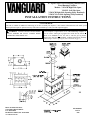
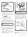
36” Open Corner Non-Circulating (Smooth Face)
Wood Burning Fireplace
Models: V36NCR Right Side Open
V36NCL Left Side Open
VI36NCR Right Side Opening (Fully Insulated)
VI36NCL Left Side Opening (Fully Insulated)
INSTALLATION INSTRUCTIONS
This Fireplace is approved for use as a Wood Burning Fireplace or
for use with a vented gas log approved to ANS Z21.60, Z21.84 or
RGA 2-72 Standards or
for use with a vent-free gas log heater
approved to ANS Z21.11.2 standard. A DESA hood must be installed
when using a vent-free gas log set (See accessories on pg. 11).
WARNING: ALWAYS LEAVE GLASS DOORS
FULLY OPENED OR FULLY CLOSED WHEN
OPERATING THIS FIREPLACE.
DESA INTERNATIONAL
2701 INDUSTRIAL DRIVE
P.O. BOX 90024
BOWLING GREEN, KY 42102-9004
www.desatech.com
PN 106480-01
REV A
6/00

1
For more information, visit www.desatech.com
CONTENTS
1. SAFETY INFORMATION --------------------------------------------------------------------------------- PG. 2
2. GLOSSARY --------------------------------------------------------------------------------- PG. 2
3. INTRODUCTION --------------------------------------------------------------------------------- PG. 2
4. BEFORE YOU BEGIN --------------------------------------------------------------------------------- PG. 2
5. SELECTING LOCATION --------------------------------------------------------------------------------- PG. 2
6. MINIMUM CLEARANCES TO COMBUSTIBLE ---------------------------------------------------------------------------- PG. 3
7. INSTALLING THE FIREPLACE --------------------------------------------------------------------------------- PG. 3
8. HEARTH EXTENSION --------------------------------------------------------------------------------- PG. 3
9. OUTSIDE AIR KIT --------------------------------------------------------------------------------- PG. 4
10. GAS LINE INSTALLATION --------------------------------------------------------------------------------- PG. 4
11. VENT FREE GAS LOG INSTALLATION --------------------------------------------------------------------------------- PG. 5
12. COLD CLIMATE INSTALLATIONS --------------------------------------------------------------------------------- PG. 5
13. CHIMNEY PIPE --------------------------------------------------------------------------------- PG. 6-7
14. PENETRATING THE ROOF --------------------------------------------------------------------------------- PG. 8
15. FLASHING INSTALLATION --------------------------------------------------------------------------------- PG. 9
16. STORM COLLAR INSTALLATIONS --------------------------------------------------------------------------------- PG. 9
17. TERMINATIONS --------------------------------------------------------------------------------- PG. 9
18. FINISHING THE FIREPLACE --------------------------------------------------------------------------------- PG. 10
19. MANTEL CLEARANCES --------------------------------------------------------------------------------- PG. 10
17. REPLACEMENT AND ACCESSORY PARTS --------------------------------------------------------------------------------- PG. 11

2
For more information, visit www.desatech.com
GLOSSARY:
a) Flush Installations – a type of installation where the front
face of the fireplace is even or leveled with the wall.
b) Chase Installation – a type of installation where the
chimney is enclosed.
c) Perpendicular Side Wall – applies to the minimum
clearance between the sidewall and fireplace opening.
d) Combustible Material – a type of material that is
flammable.
e) Nailing Flange – the extended part on both sides of the
fireplace face that secures the fireplace.
f) Termination – a cap that is placed at the end of the
chimney pipe.
g) Outside Air Kit – a combustion air inlet that allows
combustion air to enter the firebox area through a duct.
h) K-Factor – the thermal conductivity value that is given to
a particular material.
INTRODUCTION:
This fireplace model is a wood burning fireplace intended and
approved for installation in either residential homes or
buildings of standard construction. This fireplace system
requires the utilization of DESA 8 inch, double-wall, and
snap-lock flue pipe system. Optional glass doors in several
finishes are available for this fireplace (See Replacement and
Accessories parts on page 11).
BEFORE YOU BEGIN:
Before beginning the installation of your fireplace, read these
instructions:
• All DESA components and fireplaces are safe when
installed according to this manual. Use of any
components that have not been designed and tested for
this fireplace system may cause a fire hazard.
• The DESA warranty will be voided by and DESA
disclaims any responsibility for the following actions:
a) Modification of the fireplace, components, doors,
chimney system, air inlet system, damper control, etc.
b) Use of any component part not manufactured or
approved by DESA in combination with a DESA
fireplace system.
PROPER INSTALLATION is the most important step in
ensuring safe and continuous operation of this fireplace.
SELECTING LOCATION:
To determine the safest and most efficient location for your
fireplace, consider the following guidelines:
• The location must allow for all proper clearances (see
page 3).
• The location should be in a place where the fireplace will
not be affected by drafts such as air condition ducts,
windows or doors.
• A location that avoids the cutting of joists or roof rafters
makes installation easier.
• If an outside air kit is to be installed, accessibility to
outside combustion air must be considered. In some
cases, this can be achieved through a vented crawl space.
For more details, see section on outside air kit installation
on page 4.
• If a gas line is to be installed, consider the location of gas
supply.
WARNING: SAFETY INFORMATION
• Do not store or use gasoline or any other flammable
vapors or liquids in the vicinity of this or any other
appliance.
• Due to high temperatures, the appliance should be
located out of traffic and away from furniture and
draperies.
• Do not place clothing or other flammable materials on
or near the appliance.
•
N
EVER leave children unattended when a fire is
burning in the fireplace.
• Improper installation, adjustment, alteration, services
or maintenance can cause injury, property damage, or
loss of life. Refer to this manual for assistance or
additional information. Consult a qualified installer or
local distributor.
• Check local and applicable codes before installing this
fireplace.
• This wood burning fireplace complies with the UL
127 standard as a FACTORY BUILT FIREPLACE.
• Do not install a fireplace insert in this firebox unless
the manufacturer’s instructions with the insert
specifically state this firebox has been tested for use
with the insert.
• This fireplace is not intended to be used as a substitute
for a furnace to heat an entire home. Use for
supplementary heating only.
• This model is not for use in manufactured housing
(mobile homes).

3
For more information, visit www.desatech.com
MINIMUM CLEARANCES TO COMBUSTIBLES:
• Back and sides of fireplace …………………….. ¾” min.
• Top spacers …………………………………….. 0” min.
• Perpendicular side wall to opening of unit ……. 18” min.
• Bottom of fireplace to floor
(see step 2 under installing a fireplace) ……….... 0” min.
• Mantel clearances ………………………… see page 10
• Chimney outer pipe surfaces …………………. 2” min.
• Chase inside dimension …………………… 16-1/2” min.
INSTALLING THE FIREPLACE:
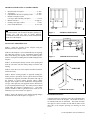
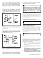
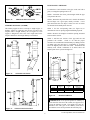
STEP 1: Frame the opening for the fireplace using the
dimensions shown in figures 1 & 2.
STEP 2: If the fireplace is to be installed directly on carpeting,
tile (other than ceramic), or any combustible material other
than wood flooring; the fireplace must be installed upon a
metal or wood panel extending the full width and depth of the
fireplace.
STEP 3: Set the fireplace directly in front of this opening and
slide the unit back until the nailing flanges touch the side
framing.
STEP 4: Check the level of the fireplace and shim with sheet
metal if necessary.
STEP 5: Before securing fireplace to prepared framing, the
ember protector (provided), must be placed between hearth
extensions (not supplied), and under the bottom front edge of
the fireplace to protect against glowing embers falling
through. If the fireplace is to be installed on a raised platform,
a Z-type ember protector (not supplied) must be fabricated to
fit your required platform height. The ember protector should
extend under the fireplace a minimum of 1”. The ember
protector should be made of galvanized sheet metal (28 Ga.
minimum) to prevent corrosion (see figure 4).
STEP 6: Secure the fireplace to the framing through flanges
located on the sides of the fireplace (see figure 3).
HEARTH EXTENSION:
A hearth extension is required to protect the combustible floor
constructed in front of the fireplace. The hearth extension is
not included and must be fabricated. The hearth extension
must project at least 12 inches one side and 20 inches on the
other side of the fireplace opening (see drawing on front
cover).
WARNING: Do not pack air spaces with insulation or
any other material. Do not obstruct fireplace openings (ie.
louvers, etc.) with any type of facing material.
Combustible material must not be in contact with the back
front face of the fireplace.
Figure 1 FRAMING DIMENSIONS
Figure 2 CORNER INSTALLATION
Figure 3 NAILING FLANGES

4
For more information, visit www.desatech.com
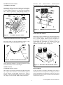
The hearth extension must be made of non-combustible,
inorganic material having an effective thermal conductivity
“K” of 0.84 BTU IN/FT.HR.F (or less) at 1 inch thick.
Thermal conductivity “K” of materials can be obtained from
the manufacturer of the non-combustible material. The
minimum required thickness for any material could be
obtained by the following formula:
K factor at 1 inch
= thickness required
0.84
For example, if the material selected has a K factor of 0.25,
such as a glass fiber, the following formula would apply:
0.25
= 0.30 thickness required
0.84
If the hearth extension is to be covered, use non-combustible
material such as tile, slate, brick, concrete, metal, glass,
marble, stone etc. Provide a means to prevent the hearth
extension from shifting and seal the gap between the fireplace
frame and hearth extension with a non-combustible material
(see figure 4).
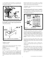
OPTIONAL OUTSIDE AIR KIT (MODELS AK4 OR
AK4F):
The outside air kit must be installed during the rough framing
of the fireplace due to the nature of its location. Outside
combustion air can be accessed through an exterior wall
(Model AK4) or a vented crawl space (Model AK4F). See
figure 5 and Accessories on page 11.
Avoid installing outside air eyebrow in areas where inlet
opening may be blocked by snow, bushes or other obstacles.
It should also be located beyond the reach of children. The
maximum height of air inlet above platform of fireplace is 3 ft.
below the termination flue gas outlet.
For further details on the installation of the outside air kit,
please refer to the instructions included with the air kit. For
operating instructions please refer to your owner’s manual.
The outside air handle is located at the left-hand side of the
fireplace refractory (see figure 6, Model V(I)36NCR shown).
To close, pull down; to open, push up. Always open the
mechanism when starting a fire to provide adequate outside
combustion air. Close the mechanism when not in use to
prevent cold air from entering the room.
GAS LINE INSTALLATION (OPTIONAL):
Gas line hook up should be done by your supplier or a
qualified service person.
NOTE: Before you proceed, make sure your gas supply is
turned off.
WARNING: HEARTH EXTENSION IS TO BE
INSTALLED ONLY AS DESCRIBED.
Figure 5 AIR KIT INSTALLATION
CAUTION: AIR DUCTS MUST NOT TERMINATE
IN ATTIC SPACE OR GARAGE.
Figure 4 HEARTH EXTENSIONS
Figure 6 AIR KIT DAMPER ROD

5
For more information, visit www.desatech.com
A gas line may be installed for the purpose of installing a
vented or vent-free gas appliance available through your local
distributor. Use a ½” black iron pipe and appropriate fittings.
When installing a gas line, a shut-off valve designed for
installation outside the appliance is recommended.
STEP 1: To install, remove the knockout indentation on the
firebrick wall located approximately 2 inches above the
refractory hearth floor on the required side. The knockout
indentation must be firmly tapped with any solid object until it
is released. Remove fragmented portions of refractory (see
figure 7).
STEP 2: Remove gas line cover plate on rear of fireplace and
pull out insulation from gas line conduit sleeve. Save
insulation for reuse.
STEP 3: Run a ½” (I.D.) black iron gas line into the fireplace
through the gas line conduit sleeve (if using a raised platform,
add height). Provide sufficient gas line into fireplace chamber
for fitting connection (see figure 8).
NOTE: Secure incoming gas line to wood framing to provide
rigidity for threaded end.
STEP 4: Repack insulation around gas line and into sleeve
opening. Seal any gaps between gas line and refractory
knockout hole with refractory cement or commercial furnace
cement. Install the decorative gas appliance or cap-off gas
line if desired. Follow the manufacturer’s installation
instructions provided with the gas appliance.
VENT-FREE GAS LOG INSTALLATION:
If you wish to install an unvented gas log set, only unvented
gas log sets, which have been found to comply with the
standard for unvented room heaters, ANS Z21.11.2, are to be
installed in this fireplace.
NOTE: A DESA hood must be installed when using an
unvented gas log set (see accessories on page 11).
VENTED GAS LOG INSTALLATION:
If you install a decorative gas appliance (vented gas log), the
decorative gas appliance must comply with the Standard for
Decorative Gas Appliance for Installation in solid fuel burning
fireplace, ANS Z21.60-1996, Z21.84 or RGA 2-72, and shall
also be installed in accordance with the National Fuel Gas
Code, ANS Z223.1-1996.
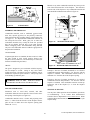
COLD CLIMATE INSTALLATIONS:
The following installation procedures are recommended when
installing a fireplace system in a cold climate area. Following
these steps will aid in reducing cold air infiltration from the
fireplace enclosure into living space.
1. The fireplace must be placed on a solid continuous
surface. You should insulate under the fireplace in all
cold climate areas.
2. In the case of a raised platform or cantilevered chase, you
should insulate under the structure to reduce air
infiltration.
3. Insulate the walls of the chase, both on the outer and
interior partitioning wall (see figure 9). Clearances from
pipe to insulating materials must be maintained.
4. Using a firestop spacer in the chase at the ceiling level is
recommended for safety and reducing cold air movement
(see accessories on page 11).
Figure 7 GAS LINE KNOCKOUT
Figure 8 GAS LINE INSTALLATION
CAUTION: All gas piping and connections must be
tested for leaks after the installation is completed. After
ensuring that the gas valve is on, apply a soap and water
solution to all connections and joints. Bubbles forming
show a leak. Correct all leaks at once. DO NOT USE AN
OPEN FLAME FOR LEAK TESTING AND DO NOT
OPERATE ANY APPLIANCE IF A LEAK IS
DETECTED.
WARNING: Do not operate an unvented gas log set in
this fireplace with the chimney removed.
WARNING: When using a decorative gas appliance,
the damper must be removed or permanently locked in the
full
y
o
p
ened
p
osition.

6
For more information, visit www.desatech.com
5. Do not insulate on top of the firebox. The opening in the
collar around the chimney at the top of the fireplace must not
be obstructed (see figure 10).
6. Before finishing the fireplace enclosure, inspect all joints of
the outer firebox. Seal any gaps of the outer firebox with a
non-combustible material. Caulk any gaps between the
nailing flange and framing.
CHIMNEY SYSTEM:
CHIMNEY HEIGHT
Minimum chimney height measured from bottom of fireplace
to flue gas outlet-end of the termination is:
Straight run 14 feet
Run with one elbow set 15 feet
Run with two elbow sets 15 feet
An elbow set is consist of one starter elbow and one return
elbow. Uncommon circumstances such as neighboring hills,
tall trees, or strong wind areas can cause downdrafts in the
chimney system. In such cases, going beyond the minimum
recommended height would be preferable to provide a better
draw.
Maximum height approved for any chimney run with this
fireplace system is 60 feet as measured from the bottom of the
fireplace to the flue outlet-end of the termination.
ASSEMBLING AND INSTALLING THE DOUBLE WALL
CHIMNEY SYSTEM
The DESA chimney system consists of 12, 18, 24, 36 and 48-
inch, snap-lock double-wall pipe segments, planned for
maximum adaptability to individual site requirements. Actual
lengths gained (lineal gain) after fitting overlaps must be taken
into consideration (see figure 11).
Each double wall chimney section consists of a galvanized
outer pipe, a stainless steel inner flue pipe and a wire spacer.
The pipe sections must be assembled independently as the
chimney is installed. When attaching the chimney directly to
the fireplace, the inner flue pipe section must be installed first
with the female side up (see figure 11). The outer pipe section
can then be installed over the flue pipe section with the male
end up.
Press down on each pipe section until the lances securely
engage the hem on the fireplace starter. The wire will assure
the proper spacing between the inner and outer pipe sections
(see figure 11).
Continue to assemble chimney sections as outlined above,
making sure that both the inner and outer pipe sections are
locked together.
When installing double wall “snap-lock” chimney together, it
is important to insure that the joint between the chimney
sections is locked. Check by pulling chimney upward after
locking. The chimney will not come apart if properly locked.
It is not necessary to add screws to keep the chimney together.
However, if desired, use screws per directions provided on
page 7, figure 13.
Figure 9 COLD CLIMATE INSTALLATION
Figure 11 LINEAL GAIN
Figure 10 FIREPLACE COLLAR OPENING

7
For more information, visit www.desatech.com
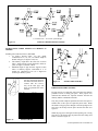
INSTRUCTIONS WHEN OFFSET OF CHIMNEY IS
NEEDED
Installing offset and return elbow (30E-8DM)
1. To achieve desired offset, you may install
combination of 12”, 18”, 24”, 36” and 48” length of
double wall pipe (see figures 12 and 13).
2. The chimney weight above the offset rest on return
elbow. Straps must be securely fastened to rafters or
joists (see figure 14, details A & B).
3. Maximum length of pipe between supports (return
elbow or chimney support V12S-8DM) is 6’ of
angled run. Maximum of two (2) 6’ angled run
sections per chimney system.
FIRESTOP SPACERS: (FS-8DM)
Firestop spacers are required at each point where the chimney
penetrates a floor or ceiling joist space. Their purpose is to
establish and maintain the required clearance between the
chimney and the combustible materials.
They also provide complete separation from one floor space to
another floor or attic space as required by most codes. When
the double wall pipe passes through a framed opening into an
attic space, the firestop must be place into the attic floor as in
figure 15.
When the pipe passes through a framed opening into a living
space above, the firestop must be placed onto the ceiling from
below as shown in figure 15.
1 or 2 elbow sets – 15 to 60 ft. system height
Figure 12 TYPICAL OFFSET INSTALLATIONS
Figure 13 OFFSET CHART
All pipe connections between
the offset and return must be
secured with two screws,
only on the outer pipe, and
must not penetrate the inner
stainless.
OFFSET RISE
A
B 48" 36" 24" 18" 12"
4 - 3/8 16 -3/8
9 - 3/4 25 - 1/2 1
12 - 3/4 30 - 3/4 1
15 34 - 3/4 1
18 40 1 1
21 - 1/4 46 - 1/4 1
23 - 3/4 49 - 1/4 1 1
27 - 3/4 56 - 3/4 1
30 60 - 3/4 1 1
33 66 1 1
36 71 1 1
38 - 1/4 75 2
41 - 1/4 80 - 1/4 1 1 1
45 86 - 3/4 2
46 - 3/4 89 - 1/2 1 1 1
51 97 1 1
53 - 1/4 101 2 1
56 - 1/4 106 - 1/4 2
59 - 1/4 111 - 1/2 1 1 1
61 - 3/4 115 - 1/2 2 1
64 - 3/4 120 - 3/4 2 1
68 - 1/4 127 1 2
70 130 2 1 1
74 - 1/4 137 - 1/2 1 2 1
76 - 3/4 141 - 1/2 1 2 1
79 - 3/4 146 - 3/4 4
ELBOW SET ONLY
CHIMNEY LENGTH
Figure 14 OFFSET PIPE SUPPORT

8
For more information, visit www.desatech.com
SUPPORT SECTIONS: (12S-8DM)
The chimney support section is a 4-strap 12” length of pipe. A
chimney support is required at the 30-foot level above the
fireplace after a straight chimney run (see figure 16). This
support is designed to relieve the extra weight load on the
fireplace and elbows when high chimneys are installed.
PENETRATING THE ROOF:
To maintain a 2-inch clearance to the pipe on the roof with a
pitch, a rectangular opening must be cut.
STEP 1: Determine the center point through which the pipe
will penetrate the roof.
STEP 2: Determine the pitch of the roof. Pitch is the distance
the roof drops over a given span, usually 12 inches. A 6/12
pitch means that the roof drops 6 inches for each 12 inches
one measures horizontally down the roof.
STEP 3: Use the roof-opening chart (see figure 18) to
determine the correct opening length and flashing required.
STEP 4: Remove the shingles around the opening measured
and cut out this section.
STEP 5: Add the next sections of the pipe until the end
penetrates the roofline. Check to see that the proper
clearances are maintained. Extend chimney by adding sections
of double wall pipe until pipe is a minimum of 30 inches
above the highest point of the roof cutout. Termination and
chimney must extend a minimum of 36 inches above the
highest point where it passes through roof.
Figure 15 FIRESTOP INSTALLATION
IMPORTANT: If an exposed portion of chimney is
greater than four feet above the roofline, use support wires
to keep the chimney secured. The support wires may be
attached to the outer pipe of the chimney with screws
provided the screws do not penetrate the inner flue pipe.
Fi
g
ure 16 SUPPORT SECTIONS
Figure 17 TYPICAL INSTALLATION
Figure 18 ROOF FLASHINGS
PITCH SLOPE OPENING "A" MAX USE FLASHING
(degrees) (inches) MODEL NO.
FLAT 0 17 V6F-8DM
0 - 6/12 26.6 19 - 1/8 V6F-8DM
6/12 - 12/12 45.0 24 - 1/4 V12F-8DM

9
For more information, visit www.desatech.com
FLASHING INSTALLATION:
(V6F-8DM or V6F-8DM)
Determine the flashing to be used with the roof-opening chart.
Slide flashing over pipe until base is flat against roof. Replace
as many shingles as needed to cover exposed area and flashing
base. Secure in position by nailing through shingles (see
figure 19). DO NOT NAIL THROUGH FLASHING CONE.
STORM COLLAR INSTALLATION: (VSC1-8DM)
Place storm collar over pipe and slide down until it is snug
against the open edge of the flashing (see figure 20).
Apply waterproof caulking to all seams and notches around
storm collar and also at base around shingles.
TERMINATIONS:
STANDARD INSTALLATONS:
The fireplace system must be terminated with the listed round
top or square chase terminations. The terminations approved
for this fireplace are RTL-8DM, which can be used for
flashing or chase and ETL-8DM for chase style termination
only. Figure 21 shows an RTL-8DM round top termination.
FOLLOW THE INSTALLATION INSTRUCTIONS
PROVIDED WITH THE TERMINATION BEING USED.
CHASE INSTALLATIONS:
Instructions for chase installations are included with the chase
style termination chosen. In a multiple chase installation, be
sure to provide adequate distance between terminations to
prevent smoke spillage from one termination to another. It is
recommended that terminations be separated at least 24
inches, center-to-center, and stacked at vertical height
difference of 18 inches or more (see figure 22).
10-FOOT RULE:
All flue gas outlets of chimney terminations must extend a
minimum of three feet in height above the highest point where
it passes through the roof and must be at least two feet above
the highest point of the roof that is within a horizontal distance
of ten feet (see figure 23).
Figure 19 FLASHING INSTALLATION
Figure 20 STORM COLLAR INSTALLATION
Figure 22 MULTIPLE CHASE TERMINATIONS
Figure 21 TERMINATION INSTALLATION

10
For more information, visit www.desatech.com
FINISHING THE FIREPLACE:
Combustible materials, such as wallboard, gypsum board,
sheet rock, drywall, plywood, etc. may directly contact the
sides and top front edge at nailing flanges of the fireplace face
(see figure 3). It is important that combustible materials do
not overlap the face itself. Brick, glass, tile or other non-
combustible materials may overlap the front face provided
they do not obstruct louvered slots or any other opening.
When overlapping with a non-combustible facing material,
only use a non-combustible mortar or adhesive appropriate for
the particular installation.
GLASS DOORS:
If optional glass doors are installed, all doors must be in either
the fully opened or fully closed position whenever the
fireplace is in use, otherwise, a fire hazard may be created (see
literature included with glass doors).
GRATE:
The grate is designed to prove maximum solid-fuel capacity.
Do not attempt to overfill. Doing so may cause smoke
spillage and create a fire hazard. Do not overload the grate or
obstruct the required air space beneath it. Always keep ashes
from building up under the grate.
MANTEL CLEARANCES:
Woodwork such as wood trims, mantels, and other
combustible materials must be placed at least 9 inches above
the opening of the fireplace (see figure 24).
Combustible materials above 9 inches and projecting more
than 1- ½” inches from the front face of the fireplace must be
place at least 12 inches above the fireplace opening (Ref:
NFPA std. 7-3.3.3).
Mantels or any other combustible material may butt up to the
side of the black metal face of the fireplace. The clearances
from the side of the fireplace to any combustible material and
wall should fall within the limits shown in figure 25.
Example 1: The face of a mantel, bookshelf, etc. in s made of
combustible material and protrudes 4 1/8” from the wall the
fireplace is installed. This combustible material must be a
minimum of 6” from the side of the fireplace opening.
Example 2: The face of a mantel, bookshelf, etc. in s made of
combustible material and protrudes 1 3/8” from the wall the
fireplace is installed. This combustible material can butt up
against the side of the fireplace (i.e. 2” from the fireplace
opening).
TECHNICAL SERVICE:
You may have further questions about installation, operations,
or troubleshooting. If so, contact Desa International’s
Technical Service Department at www.desatech.com
. When
contacting Desa International, have the model number of your
fireplace ready.
Figure 23 10 FOOT RULE
Fi
g
ure 24 MANTEL CLEARANCES
FIREPLACE
TOP VIEW OF FIREPLACE
OPENING
Figure 25 MINIMUM SIDE CLEARANCES
WARNING: RISK OF FIRE. REPLACE GRATE
WITH MODEL 36R GR OR 36L GR GRATE ONLY!

11
For more information, visit www.desatech.com
Desa International 2701 Industrial Drive, P.O. Box 90024, Bowling Green, KY 42102-9004 www.desatech.com, (800) 323-5190
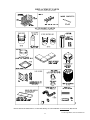
ACCESSORY PARTS
REPLACEMENT PARTS
(CONTACT YOUR LOCAL DEALER)
(CONTACT YOUR LOCAL DEALER)
-
 1
1
-
 2
2
-
 3
3
-
 4
4
-
 5
5
-
 6
6
-
 7
7
-
 8
8
-
 9
9
-
 10
10
-
 11
11
-
 12
12


Desa VI36NCR Owner's manual
- Category
- Fireplaces
- Type
- Owner's manual
Ask a question and I''ll find the answer in the document
Finding information in a document is now easier with AI
Related papers
Other documents
-
FMI VI42E Installation guide
-
-
-
-
-
Martin B36RA User manual
-
-
-
-
Bull Desa Woodburning Fireplace Operating instructions