Made in Vietnam.
SPECIFICATIONS
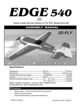
Wingspan 182 cm 71.6 in.
Wing area 50 dm
2
776 in.
Length 141 cm 55.5 in.
Weight 2.12kg 4.7lbs.
Parts Listing required (not included)
Servo 5 servos.
Radio 4 channels.
Motor AXI 2826/12.
Propeller 10/5”.
Battery CELLS-LI-POLY 3-11.2V-3500mA/h.
Speed Control MM5024-3.
Instruction Manual book

LIBERTY 182.
2
This instruction manual is designed to help you build a great flying aeroplane. Please read this
manual thoroughly before starting assembly of your LIBERTY 182. Use the parts listing below to
identify all parts.
WARNING.
Please be aware that this aeroplane is not a toy and if assembled or used incorrectly it is
capable of causing injury to people or property. WHEN YOU FLY THIS AEROPLANE YOU
ASSUME ALL RISK & RESPONSIBILITY.
If you are inexperienced with basic R/C flight we strongly recommend you contact your R/C supplier
and join your local R/C Model Flying Club. R/C Model Flying Clubs offer a variety of training
procedures designed to help the new pilot on his way to successful R/C flight. They will also be able
to advise on any insurance and safety regulations that may apply.
TOOLS & SUPPLIES NEEDED.
Thick cyanoacrylate glue.
30 minute epoxy.
5 minute epoxy.
Hand or electric drill.
Assorted drill bits.
Modelling knife.
Straight edge ruler.
2mm ball driver.
Phillips head screwdriver.
220 grit sandpaper.
90° square or builder’s triangle.
Wire cutters.
Masking tape & T-pins.
Thread-lock.
Paper towels.
Some more parts.
HARDWARE PACK
COWLING.
Landing gear.....
To avoid scratching your new airplane, do not
unwrap the pieces until they are needed for
assembly. Cover your workbench with an old
towel or brown paper, both to protect the
aircraft and to protect the table. Keep a couple
of jars or bowls handy to hold the small parts
after you open the bag.
Please trial fit all the parts. Make sure you
have the correct parts and that they fit and are
aligned properly before gluing! This will assure
proper assembly.
LIBERTY 182 ARF is hand
made from natural materials, every plane is
unique and minor adjustments may have to
be made. However, you should find the fit
superior and assembly simple.
The painted and plastic parts used in this kit
are fuel proof. However, they are not tolerant
of many harsh chemicals including the
following: paint thinner, C/A glue accelerator,
C/A glue debonder and acetone. Do not let
these chemicals come in contact with the
colors on the covering and the plastic parts.
PARTS LISTING.
FUSELAGE ASSEMBLY
(1) Fuselage.
WING ASSEMBLY
(1) Right wing half with pre-installed
aileron.
(1) Left wing half with pre-installed
aileron.
Some more parts........
Tail section assembly
(1) Vertical stabilizer with pre-
installed rudder.
(1) Horizontal stabilizer with pre-
installed elevator halves.
SUGGESTION.
NOTE.

INSTRUCTION MANUAL.
3
+ This is not a toy
+ Be sure that no other flyers are using your
radio frequency.
+The glow plug clip must be securely attached
to the glow plug.
+ Do not flip the propeller with your fingers.
+ Keep loose clothing and wires away from
the propeller.
+ Do not start the engine if people are near.
Do not stand in line with the side of the
propeller.
+ Make engine adjustments from behind the
propeller only. Do not reach around the
spinning propeller.
SAFETY PRECAUTION.
1) Install the rubber grommets and brass
eyelets onto the aileron servos.
INSTALLING THE AILERON SERVOS.
3) Using the thread as a guide and using
masking tape, tape the servo lead to the end
of the thread: carefully pull the thread out.
When you have pulled the servo lead out,
remove the masking tape and the servo lead
from the thread.
2) Using a modeling knife, remove the
covering at possition show below.
4) Drill 1,6mm pilot holes through the block
of wood for each of the four mounting screws
provided with the servo.
Bottom of wing.
Remove the covering.
C/A glue.
Electric wire.
Thread.
Aileron servo.

LIBERTY 182.
4
2mm.
Pen.
Straitgh line.
1) Using a ruler & pen to draw a straight
line as below picture.
INSTALLING THE AILERON CONTROL HORN.
3) Drill two 2mm holes through the aileron
using the control horn as a guide and screw
the control horn in place.
2) Insert aileron control horn to the aileron.
Repeat the procedure for the other
wing half.
Aileron pushrod.
Aileron pushrod.
Cut.
2mm X 20mm.

INSTRUCTION MANUAL.
5
JOINING THE WING HALVES.
1) Location the aluminium wing dihedral
brace.
2) Test fit the dihedral brace into each wing
haft. The brace should slide in easily. If not,
use 220 grit sand down the edges and ends
of the brace until it fits properly.
INSTALLING ELECTRIC MOTOR.
Aluminium
brace.
Dowel brace.
C/A glue.
Motor.
Rotor shaft.
Push.

LIBERTY 182.
6
Front view.
COWLING.
1) Slide the cowl over the motor and line
up the back edge of the cowl with the marks
you made on the fuselage.
3x12mm.
Steering arm.
Pushrod wire.
Adjust the nose gear steering arm untill the
arm is parallel with fire wall.
NOSE GEAR INSTALLATION.
3x10mm.
3) Slide the cowl back over the motor.
2) While keeping the back edge of the
cowl flush with the marks, align the front of
the cowl with the crankshaft of the motor. The
front of the cowl should be positioned so the
crankshaft is in nearly the middle of the cowl
opening. Hold the cowl firmly in place using
pieces of masking tape.
Machine screw.

INSTRUCTION MANUAL.
7
1) Using a modeling knife, remove the
covering from over the two main gear mounting
slots located in the bottom of the fuselage.
2) Using the two landing gear straps as a
guide, mark the locations of the four mounting
screws onto the fuselage surface.
3) The landing gear wire is held in place
using two nylon landing gear straps and four
wood screws.
MAIN GEAR INSTALLATION.
3x12mm.
C/A glue.
Covering.
SERVO INSTALLATION.
See pictures bellow:

LIBERTY 182.
8
See pictures below:
Using a modeling knife, cut the covering
from the horizontal stabilizer and remove it.
Check to mark sure the wing and stabilizer
are paralell. If they are not, lightly sand the
opening in the fuselage for the stabilizer until
the stabilizer is paralell to the wing.
Remove covering.
Drill bit.
HORIZONTAL STABILIZER.
Elevator
pushrod.
Nose gear.
Rudder
pushrod
Tail case.
Tail case.

INSTRUCTION MANUAL.
9
90º
Vertical
Stabilizer.
Horizontal
Stabilizer.
C/A glue.
2) While holding the vertical stabilizer
firmly in place, use a pen and draw a line on
each side of the vertical stabilizer where it
meets the top of the fuselage.
3) Remove the vertical stabilizer. Using
a modeling knife, remove the covering from
below the lines you drew.
When cutting through the covering to re-
move it, cut with only enough pressure to only
cut through the covering itself. Cutting into
the balsa structure may weaken it.
4) Slide the vertical stabilizer back in
place. Using a triangle, check to ensure that
the vertical stabilizer is aligned 90º to the hori-
zontal stabilizer.
1) Slide the vertical stabilizer into the slot
in the top of the tail case.
VERTICAL STABILIZER.
the sides and bottom of the vertical stabilizer
mounting area. Double check all of your mea-
surements once more before the epoxy cures.
Hold the stabilizer in place with T-pins or mask-
ing tape and remove any excess epoxy using a
paper towel and rubbing alcohol. Allow the ep-
oxy to fully cure before proceeding.
C/A glue.
5) When you are sure that everything is
aligned correctly, mix up a generous amount of
Flash 30 Minute Epoxy. Apply a thin layer to the
mounting slot in the top of the tail case and to
ELEVATOR CONTROL HORN
PUSHROD INSTALLATION.
1) Locate the two nylon control horns, two
nylon control horn backplates and four M2 x
16mm machine screws.
2) Position the elevator horn on the bottom
side of elevator. The clevis attachment holes
should be positioned over the hinge line.
C/A glue.

LIBERTY 182.
10
RUDDER CONTROL HORN
PUSHROD INSTALLATION.
1) Locate the two nylon control horns, two
nylon control horn backplates and four M2 x
16mm machine screws.
2) Position the rudder horn on the bottom
side of rudder.
3) Using a 1.5mm drill bit and the control
horns as a guide, drill the mounting holes
through the rudder halves.
2 x 16mm.
Rudder control horn.
Rudder pushrod.
Control Horn.
Mounting Screws.
Mounting Plate.
3) Using a 1.5mm drill bit and the control
horns as a guide, drill the mounting holes
through the elevator halves.
Control horn.
Elevator
pushrod.
2 x 16mm.

INSTRUCTION MANUAL.
11
Elevator pushrod.
Rudder
pushrod.
Nose gear.
INSTALLING THE CANDY ROOM
SERVOS.
2 x 12mm.
Cut.
Candy room.
1) Plug the servo leads and the switch
lead into the receiver. You may want to plug
an aileron extension into the receiver to make
plugging in the aileron servo lead easier
when you are installing the wing . Plug the
battery pack lead into the switch.
INSTALLING THE RECEIVER AND BATTERY.
Cut.

LIBERTY 182.
12
3) Do not permanently secure the receiver
and battery until after balancing the model.
4) Using a 2mm drill bit, drill a hole through
the side of the fuselage, near the receiver, for
the antenna to exit.
WING STRUT INSTALLATION.
Parts requirement. See pictures below:
Remove covering.
Installing aluminium plate follow pictures
below:
3x10mm.
2) Wrap the receiver and battery pack in
the protective foam to protect them from
vibration. Use a rubber band or masking tape
to hold the foam in place.
Aluminium plate.
Aluminium plate.
Wing panel.
Drill bit.
Speed control.
Battery.
Ruber bend.

INSTRUCTION MANUAL.
13
Attachment wing-fuselage.
C/A glue.
Wing panel.
Aluminium plate.
Plastic parts.

LIBERTY 182.
14
Aluminium plate.
Cut nylon screw long 10mm by modeling
knife as picture above.

INSTRUCTION MANUAL.
15
Ailerons : 15mm up 15mm down
Elevator : 15mm up 15mm down
Rudder : 25mm right 25mm left
1) We highly recommend setting up a
plane using the control throws listed.
2) The control throws should be measured
at the widest point of each control surface.
3) Check to be sure the control surfaces
move in the correct directions.
CONTROL THROWS.
1) It is critical that your airplane be balanced
correctly. Improper balance will cause your
plane to lose control and crash.
THE CENTER OF GRAVITY IS LOCATED
9cm BACK FROM THE LEADING EDGE OF
THE WING, AT THE FUSELAGE.
BALANCING.
2) Turn the airplane upside down. Place
your fingers on the masking tape and carefully
lift the plane .
CG
9CM
Ailerons Control
1) Completely charge your transmitter and
receiver batteries before your first day of flying.
2) Check every bolt and every glue joint in
your plane to ensure that everything is tight
and well bonded.
3) Double check the balance of the
airplane.
4) Check the control surface.
5) Check the receiver antenna . It should
be fully extended and not coiled up inside the
fuselage.
6) Properly balance the propeller.
We wish you enjoy.
PRE-FLIGHT CHECK.
/