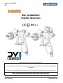
DeVilbiss DV1 Clearcoat Spray Gun User manual
- Category
- Power fine-spray systems
- Type
- User manual
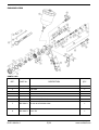
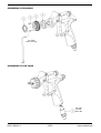
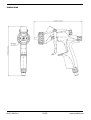
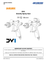
DeVilbiss DV1 Clearcoat Spray Gun is a professional quality spray gun designed to comply with all global legislations. It is suitable for use with solvent and water based materials. The gun has a lightweight design and is easy to use, making it ideal for a variety of applications. The DV1 Clearcoat Spray Gun features a high-performance air cap that provides excellent atomization and a consistent spray pattern. The gun also has a fully adjustable spray pattern, allowing you to customize the spray to meet your specific needs.
DeVilbiss DV1 Clearcoat Spray Gun is a professional quality spray gun designed to comply with all global legislations. It is suitable for use with solvent and water based materials. The gun has a lightweight design and is easy to use, making it ideal for a variety of applications. The DV1 Clearcoat Spray Gun features a high-performance air cap that provides excellent atomization and a consistent spray pattern. The gun also has a fully adjustable spray pattern, allowing you to customize the spray to meet your specific needs.


-
 1
1
-
 2
2
-
 3
3
-
 4
4
-
 5
5
-
 6
6
-
 7
7
-
 8
8
-
 9
9
-
 10
10
-
 11
11
-
 12
12
-
 13
13
-
 14
14
-
 15
15
-
 16
16
-
 17
17
-
 18
18
-
 19
19
-
 20
20
-
 21
21
-
 22
22
-
 23
23
-
 24
24


DeVilbiss DV1 Clearcoat Spray Gun User manual
- Category
- Power fine-spray systems
- Type
- User manual
DeVilbiss DV1 Clearcoat Spray Gun is a professional quality spray gun designed to comply with all global legislations. It is suitable for use with solvent and water based materials. The gun has a lightweight design and is easy to use, making it ideal for a variety of applications. The DV1 Clearcoat Spray Gun features a high-performance air cap that provides excellent atomization and a consistent spray pattern. The gun also has a fully adjustable spray pattern, allowing you to customize the spray to meet your specific needs.
Ask a question and I''ll find the answer in the document
Finding information in a document is now easier with AI
Related papers
-
 DeVilbiss DV1 Basecoat Spray Gun User manual
-
 DeVilbiss JGA Maintenance And Troubleshooting Manual
-
 DeVilbiss Pro Lite E User manual
-
 DeVilbiss GTI PRO LITE Operating instructions
-
 DeVilbiss GTi® Gravity User manual
-
Carlisle EGA™ Pressure Feed Owner's manual
-
DeVilbiss BINKS - AG364 Owner's manual
-
 DeVilbiss PLUS® Gravity User manual
-
 DeVilbiss 802343 User guide
-
 DeVilbiss Hose Fittings User manual


Other documents
-
Paasche HG-08 User manual
-
Carlisle DeVILBISS - GPG Gravity Spray Gun User manual
-
-
-
-
-
-
-
-