Page is loading ...

1100 © 2000 Titan Tool Inc. All rights reserved. Form No. 313-1435, REV C
Printed in the U. S. A.
Do not use this equipment before reading this manual!
550
XC Airless Sprayer
Owner’s Manual
For professional use only
NOTE: This manual contains important warnings
and instructions. Please read and retain for
reference.
Model Numbers:
120V Skid, Bare 765-2000
120V Skid, Complete 765-2001
120V Low Rider, Bare 765-2002
120V Low Rider, Complete 765-2003
120V High Rider, Bare 765-2004
120V High Rider, Complete 765-2005

Table of Contents
Safety Precautions..................................................................2
Français...............................................................................12
Español................................................................................14
General Description ................................................................4
Operation .................................................................................4
Pre-Start ................................................................................4
Purging and Priming..............................................................4
Operating the Spray Gun ......................................................5
Pressure Relief Procedure ....................................................5
Spraying...................................................................................6
Spraying Technique ...............................................................6
Practice..................................................................................6
Cleanup ....................................................................................7
Flushing the Unit ...................................................................7
Maintenance ............................................................................7
General Repair and Service Notes .......................................7
Daily Maintenance.................................................................7
Spray Gun Maintenance........................................................8
Accessories .............................................................................8
Troubleshooting ....................................................................10
Airless Pump .......................................................................10
Airless Gun..........................................................................10
Spray Patterns .....................................................................11
Parts Lists and Service Instructions...................................16
Main Assembly ....................................................................16
Motor Assembly...................................................................17
Gear Box Assembly.............................................................18
Fluid Section Assembly .......................................................20
Siphon Assembly.................................................................21
Filter Block Assembly ..........................................................22
Low Rider Frame Assembly ................................................23
High Rider Frame Assembly................................................23
Skid Assembly .....................................................................23
Warranty.................................................................................24
Safety Precautions
This manual contains information that must be read and
understood before using the equipment. When you come to an
area that has one of the following symbols, pay particular
attention and make certain to heed the safeguard.
This symbol indicates a potential hazard that may cause
serious injury or loss of life. Important safety information
will follow.
This symbol indicates a potential hazard to you or to the
equipment. Important information that tells how to prevent
damage to the equipment or how to avoid causes of minor
injuries will follow.
HAZARD: Injection injury - A high pressure stream
produced by this equipment can pierce the skin
and underlying tissues, leading to serious
injury and possible amputation. See a
physician immediately.
DO NOT TREAT AN INJECTION INJURY AS A SIMPLE CUT!
Injection can lead to amputation. See a physician
immediately.
The maximum operating range of the pump is 3200
PSI/221BAR fluid pressure.
WARNING
NOTE: Notes give important information which should
be given special attention.
CAUTION
WARNING
2©Titan Tool Inc. All rights reserved.
PREVENTION:
• NEVER aim the gun at any part of the body.
• NEVER allow any part of the body to touch the fluid
stream. DO NOT allow body to touch a leak in the fluid
hose.
• NEVER put your hand in front of the gun. Gloves will not
provide protection against an injection injury.
•ALWAYS lock the gun trigger, shut the pump off, and
release all pressure before servicing, cleaning the tip or
guard, changing tip, or leaving unattended. Pressure will
not be released by turning off the motor. The
PRIME/SPRAY valve must be turned to PRIME to relieve
the pressure. Refer to the PRESSURE RELIEF
PRESSURE described in the pump manual.
•ALWAYS keep the tip guard in place while spraying. The
tip guard provides some protection but is mainly a warning
device.
•ALWAYS remove the spray tip before flushing or cleaning
the system.
• The paint hose can develop leaks from wear, kinking and
abuse. A leak can inject material into the skin. Inspect
the hose before each use.
•NEVER use a spray gun without a trigger lock and trigger
guard in place and in good working order.
• All accessories must be rated at or above 3200 PSI/221
BAR. This includes spray tips, guns, extensions, and
hose.
HAZARD: EXPLOSION OR FIRE - Solvent and paint fumes
can explode or ignite. Severe injury and/or
property damage can occur.
PREVENTION:
• Provide extensive exhaust and fresh air introduction to
keep the air within the spray area free from accumulation
of flammable vapors.
•Avoid all ignition sources such as static electric sparks,
open flames, pilot lights, and hot objects. Connecting or
disconnecting power cords or working light switches can
make sparks.
•Do not smoke in spray area.
• Fire extinguisher must be present and in good working
order.
• Place paint pump at a minimum of 3 feet (preferably
more) into a separate, well ventilated room from the spray
object or at least 20 feet from the spray object in a well
ventilated area (add more hose if necessary). Flammable
vapors are often heavier than air. Floor area must be
extremely well ventilated. The paint pump contains arcing
parts that emit spark and can ignite vapors.
• The equipment and objects in and around the spray area
must be properly grounded to prevent static sparks.
• Use only conductive or grounded high pressure fluid hose.
Gun must be grounded through hose connections.
• Power cord must be connected to a grounded circuit.
• Always flush unit into a separate metal container, at low
pump pressure, with spray tip removed. Hold gun firmly
against side of container to ground container and prevent
static sparks.
• Follow the material and solvent manufacturer's warnings
and instructions.
• Use extreme caution when using materials with a
flashpoint below 70° F (21° C). Flashpoint is the
temperature that a fluid can produce enough vapors to
ignite.
NOTE TO PHYSICIAN:
Injection into the skin is a traumatic injury. It is
important to treat the injury as soon as possible. DO
NOT delay treatment to research toxicity. Toxicity is a
concern with some coatings injected directly into the
blood stream. Consultation with a plastic surgeon or
reconstructive hand surgeon may be advisable.

• Plastic can cause static sparks. Never hang plastic to
enclose a spray area. Do not use plastic drop cloths
when spraying flammable materials.
• Use lowest possible pressure to flush equipment.
GAS ENGINE (WHERE APPLICABLE)
Always place pump outside of structure in fresh air. Keep all
solvents away from the engine exhaust. Never fill fuel tank
with a running or hot engine. Hot surface can ignite spilled
fuel. Always attach ground wire from pump unit to a grounded
object, such as a metal water pipe. Refer to engine owner’s
manual for complete safety information.
HAZARD: EXPLOSION HAZARD DUE TO INCOMPATIBLE
MATERIALS - Will cause severe injury or
property damage.
PREVENTION:
• Do not use materials containing bleach or chlorine.
• Do not use halogenated hydrocarbon solvents such as
mildewcide, methylene chloride and 1,1,1 -
trichloroethane. They are not compatible with aluminum.
• Contact your coating supplier about the compatibility of
material with aluminum.
HAZARD: HAZARDOUS VAPORS - Paints, solvents,
insecticides, and other materials can be
harmful if inhaled or come in contact with the
body. Vapors can cause severe nausea,
fainting, or poisoning.
PREVENTION:
• Use a respirator or mask if vapors can be inhaled. Read
all instructions supplied with the mask to be sure it will
provide the necessary protection.
•Wear protective eyewear.
•Wear protective clothing as required by coating
manufacturer.
HAZARD: GENERAL - This product can cause severe
injury or property damage.
PREVENTION:
• Read all instructions and safety precautions before
operating equipment.
• Always disconnect the motor from the power supply
before working on the equipment.
• Follow all appropriate local, state, and national codes
governing ventilation, fire prevention, and operation.
• The United States Government Safety Standards have
been adopted under the Occupational Safety and Health
Act (OSHA). These standards, particularly part 1910 of
the General Standards and part 1926 of the Construction
Standards, should be consulted.
• Use only manufacturer authorized parts. User assumes
all risks and liabilities when using parts that do not meet
the minimum specifications and safety devices of the
pump manufacturer.
• Before each use, check all hoses for cuts, leaks, abrasion
or bulging of cover. Check for damage or movement of
couplings. Immediately replace the hose if any of these
conditions exist. Never repair a paint hose. Replace it
with another grounded high-pressure hose.
• All hoses, swivels, guns, and accessories must be
pressure rated at or above 3200PSI/221 BAR.
• Do not spray outdoors on windy days.
•Wear clothing to keep paint off skin and hair.
Grounding Instructions
This product must be grounded. In the event of an electrical
short circuit, grounding reduces the risk of electric shock by
providing an escape wire for the electric current. This product
is equipped with a cord having a grounding wire with an
appropriate grounding plug. The plug must be plugged into an
outlet that is properly installed and grounded in accordance
with all local codes and ordinances.
DANGER — Improper installation of the grounding plug can
result in a risk of electric shock. If repair or replacement of the
cord or plug is necessary, do not connect the green grounding
wire to either flat blade terminal. The wire with insulation
having a green outer surface with or without yellow stripes is
the grounding wire and must be connected to the grounding
pin.
Check with a qualified electrician or serviceman if the
grounding instructions are not completely understood, or if you
are in doubt as to whether the product is properly grounded.
Do not modify the plug provided. If the plug will not fit the
outlet, have the proper outlet installed by a qualified
electrician.
This product is for use on a nominal 120 volt circuit and has a
grounding plug that looks like the plug illustrated below. A
temporary adapter which looks like the adapter illustrated in
the figure below may be used to connect this plug to a 2 pole
receptacle as shown if a properly grounded outlet is not
available.
The temporary adapter should be used only until a properly
grounded outlet as shown below can be installed by a qualified
electrician. The green colored rigid ear, lug, or the grounding
wire extending from the adapter must be connected to a
permanent ground such as a properly grounded outlet box
cover. Whenever the adapter is used, it must be held in place
by a metal screw.
Use only a 3-wire extension cord that has a 3-blade
grounding plug and a 3-slot receptacle that will accept the
plug on the product. Make sure your extension cord is in
good condition. When using an extension cord, be sure
to use one heavy enough to carry the current your
product will draw. An undersized cord will cause a drop
in line voltage resulting in loss of power and overheating.
A 12 gauge cord is recommended. If an extension cord is
to be used outdoors, it must be marked with the suffix W-
A after the cord type designation. For example, a
designation of SJTW-A would indicate that the cord would
be appropriate for outdoor use.
NOTE: Do not use more than 50 feet of extension
cord. If you need to paint further than 100
feet from your power source, use more paint
hose, not more extension cord.
CAUTION
Grounded Outlet
Grounding Pin
Tab for
Grounding Screw
Adapter
Metal Screw
Cover for grounded outlet box
©Titan Tool Inc. All rights reserved. 3

General Description
This piston pump is a precision power tool used for spraying
many types of materials. Read and follow this instruction
manual carefully for proper operating instructions,
maintenance, and safety information.
Operation
This equipment produces a fluid stream at extremely high
pressure. Read and understand the warnings in the
Safety Precautions section at the front of this manual
before operating this equipment.
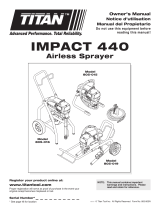
Pre-Start
Perform the following procedure before plugging in the power
cord of an electric unit.
1. Ensure that the suction set and the return hose are
attached and secure.
2. Attach a minimum of 50’ of airless spray hose to the unit.
3. Attach an airless spray gun to the spray hose. Do not
attach the tip to the spray gun yet. Remove the tip if it is
already attached.
Make sure all airless hoses and spray guns are
electrically grounded and rated for at least 3200 psi (220
bar) fluid pressure.
4. Turn the pressure control knob fully counterclockwise to
its lowest pressure setting.
5. Make sure the ON/OFF switch is in its OFF position.
6. Fill the wet cup with one tablespoon of piston seal
lubricant (P.S.L.).
Never operate unit for more than ten seconds without
fluid. Operating this unit without fluid will cause
unnecessary wear to the packings.
7. Make sure the electrical service is 120V, 15 amp
minimum.
8. Plug the power cord into a properly grounded outlet.
CAUTION
WARNING
WARNING
Electrical
Box
Paint Filter
PRIME/
SPRAY
Valve
Outlet
Fitting
Motor
Siphon Tube
Return Hose
Pressure
Control Knob
Add piston
seal lubricant
(P.S.L.) here
Fluid Section
4©Titan Tool Inc. All rights reserved.
Purging and Priming
Always keep the trigger lock on the spray gun in the
locked position while purging the system.
If this unit is new, it is shipped with test fluid in the fluid section
to prevent corrosion during shipment and storage. This fluid
must be thoroughly cleaned out of the system before you
begin spraying.
If it is already in service, you will need to purge the water or
solvent used in cleanup.
Purging and Priming the Pump for Latex Paint
1. Secure the return hose into a waste container.
2. Place the suction tube into a container of the appropriate
solvent.
3. Turn the pressure control knob fully counterclockwise its
lowest pressure setting.
4. Turn the PRIME/SPRAY valve down to the PRIME
position.
5. Move the ON/OFF switch to the ON position.
6. Slowly turn the pressure control knob clockwise to
increase the pressure until fluid starts to come out of the
return hose. Use only enough pressure to keep the fluid
coming out.
7. Turn the pressure control knob fully counterclockwise to
its lowest setting when the test fluid is purged and solvent
is coming out of the return hose.
8. Remove the container of solvent from the suction tube
and replace it with a bucket of clear water.
9. Increase the pressure to the minimum necessary to keep
fluid flowing until clear water is coming out of the return hose.
10. Turn the pressure control knob fully counterclockwise to
its lowest setting.
11. Remove the bucket of water from under the suction tube
and replace it with a container of latex paint.
12. Increase the pressure slowly until paint is coming through
the return hose.
13. Remove the return hose from the waste container and
place it in its operating position above the container of
latex paint.
14. Keep circulating the paint through the system until the
paint coming out of the return hose is free of air bubbles.
15. Turn the pressure control knob fully counterclockwise to
its lowest setting.
The pump is now purged. Skip to Purging and Priming the
Spray Hose.
Purging and Priming for Solvent-Based Paint
1. Secure the return hose into a waste container.
2. Place the suction tube into a container of the appropriate
solvent.
3. Turn the pressure control knob fully counterclockwise to
its lowest pressure setting.
4. Turn the PRIME/SPRAY valve down to the PRIME
position.
5. Move the ON/OFF switch to the ON position.
6. Slowly turn the pressure control knob clockwise to
increase the pressure until fluid starts to come out of the
return hose. Use only enough pressure to keep the fluid
coming out.
7. Turn the pressure control knob fully counterclockwise to
its lowest setting when the test fluid is purged and solvent
is coming out of the return hose.
8. Remove the container of solvent from under the suction
tube and replace it with a container of solvent-based
paint.
9. Increase the pressure slowly until paint is coming through
the return hose.
WARNING

10. Remove the return hose from the waste container and
place it in its operating position above the container of
solvent-based paint.
11.Keep circulating the paint through the system until the
paint coming out of the return hose is free of air bubbles.
12. Turn the pressure control knob fully counterclockwise to
its lowest setting.
The pump is now purged. Go to Purging and Priming the
Spray Hose.
Purging and Priming the Spray Hose
After the pump is purged and primed, you must do the same
for the spray hose.
If a metal container is used, ground the
gun by holding it against the edge of
the container while flushing. Failure to
do so may lead to a static electric
discharge which may cause a fire.
1. Turn the pressure control knob fully
counterclockwise to its lowest pressure setting.
2. Turn the PRIME/SPRAY valve up to the SPRAY position.
3. Unlock the gun by turning the gun trigger lock to the
unlocked position.
4. Turn the pressure control knob slowly clockwise to
increase pressure.
5. Trigger the gun into a waste container until all air, water,
or solvent is purged from the spray hose and paint is
flowing freely.
6. Lock the gun by turning the gun
trigger lock to the locked position.
7. Set down the gun and allow the unit
to pressurize.
8. Check the entire system for leaks.
If leaks occur, follow the Pressure
Relief Procedure in this manual
before tightening any fittings or
hoses.
Be sure to follow the “Pressure Relief Procedure” outlined
in this section when shutting the unit down for any
purpose, including servicing or adjusting any part of the
spray system, changing or cleaning spray tips, or
preparing for cleanup.
9. Unlock the gun by turning the gun trigger lock to the
unlocked position.
10. Turn the pressure control knob fully counterclockwise to
its lowest pressure setting.
11.Turn the PRIME/SPRAY valve down to the PRIME
position and trigger the gun into the waste container to be
sure that no pressure is left in the hose.
12. Lock the gun by turning the gun trigger lock to the locked
position.
WARNING
Trigger lock
in locked position.
WARNING
NOTE: Make sure that the spray gun does not have a
tip installed.
Operating the Spray Gun
POSSIBLE INJECTION HAZARD. Do not spray without the
tip guard in place. Never trigger the gun unless the tip is
in either the spray or the unclog position. Always engage
the gun trigger lock before removing, replacing or
cleaning tip.
Preparing to Spray
1. Move the ON/OFF switch to the OFF position.
2. Make sure the gun trigger lock is in the locked position.
3. Attach tip guard and tip to the gun as instructed by the tip
guard or tip manuals.
4. Move the ON/OFF switch to the ON position.
5. Turn the PRIME/SPRAY valve up to the SPRAY position.
6. Test the spray pattern on a piece of cardboard. Adjust the
pressure control knob until the spray from the gun is
completely atomized.
Pressure Relief Procedure
Be sure to follow the “Pressure Relief Procedure” when
shutting the unit down for any purpose, including
servicing or adjusting any part of the spray system,
changing or cleaning spray tips, or preparing for cleanup.
1. Lock the gun by turning the gun
trigger lock to the locked position.
2. Move the ON/OFF switch to the
OFF position.
3. Turn the pressure control knob
counterclockwise to its lowest
setting.
4. Unlock the gun by turning the gun
trigger lock to the unlocked position.
5. Hold the metal part of the gun firmly to
the side of a metal container to ground
the gun and avoid a build up of static
electricity.
6. Trigger the gun to remove any
pressure that may still be in the hose.
7. Lock the gun by turning the gun trigger lock to the locked
position.
8. Turn the PRIME/SPRAY valve down to the PRIME
position.
Trigger lock
in locked position.
WARNING
WARNING
©Titan Tool Inc. All rights reserved. 5

Spraying
POSSIBLE INJECTION HAZARD. Do not spray without the
tip guard in place. Never trigger the gun unless the tip is
in either the spray or the unclog position. Always engage
the gun trigger lock before removing, replacing, or
cleaning tip.
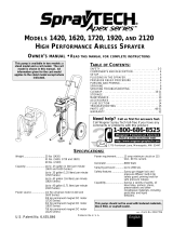
Spraying Technique
The following techniques, if followed, will assure professional
painting results.
Hold the gun perpendicular to the surface and always at equal
distance from the surface. Depending on the type of material,
surface, or desired spray pattern, the gun should be held at a
distance of 12 to 14 inches (30 to 35 cm).
Move the gun either across or up and down the surface at a
steady rate. Moving the gun at a consistent speed conserves
material and provides even coverage. The correct spraying speed
allows a full, wet coat of paint to be applied without runs or sags.
Holding the gun closer to the surface deposits more paint on
the surface and produces a narrower spray pattern. Holding
the gun farther from the surface produces a thinner coat and
wider spray pattern. If runs, sags, or excessive paint occur,
change to a spray tip with a smaller orifice. If there is an
insufficient amount of paint on the surface or you desire to
spray faster, a larger orifice tip should be selected.
Maintain uniform spray stroke action. Spray alternately from
left to right and right to left. Begin movement of the gun before
the trigger is pulled.
Avoid arcing or holding the gun at an angle. This will result in
an uneven finish.
Proper lapping (overlap of spray pattern) is essential to an
even finish. Lap each stroke. If you are spraying horizontally,
aim at the bottom edge of the preceding stroke, so as to lap
the previous pattern by 50%.
Too Thick
Offspray
Arcing Gun at angle
start
stroke
release
trigger
pull
trigger
end
stroke
WARNING
6©Titan Tool Inc. All rights reserved.
For corners and edges,
split the center of the
spray pattern on the
corner or edge and spray
vertically so that both
adjoining sections receive
approximately even
amounts of paint.
If conditions are windy, angle the
spray pattern into the wind to
minimize drifting. Work from
ground to roof. Do not attempt
to spray if wind is excessive.
When spraying with a shield,
hold it firmly against the surface. Angle the spray gun slightly
away from the shield and toward the surface. This will prevent
paint from being forced underneath.
Shrubs next to houses should be tied back and covered with a
canvas cloth. The cloth should be removed as soon as
possible. Titan gun extensions are extremely helpful in these
situations.
Nearby objects such as automobiles, outdoor furniture, etc.
should be moved or covered whenever in the vicinity of a
spray job. Be careful of any other surrounding objects that
could be damaged by overspray.
Practice
1. Be sure that the paint hose is free of kinks and clear of
objects with sharp cutting edges.
2. Turn the pressure control knob counterclockwise to its to
its lowest setting.
3. Turn the PRIME/SPRAY valve up to its SPRAY position.
4. Turn the pressure control knob clockwise to its highest
setting. The paint hose should stiffen as paint begins to
flow through it.
5. Unlock the gun trigger lock.
6. Trigger the spray gun to bleed air out of the hose.
7. When paint reaches the spray tip, spray a test area to
check the spray pattern.
8. Use the lowest pressure
setting necessary to get a
good spray pattern. If the
pressure is set too high, the
spray pattern will be too light.
If the pressure is set too low,
tailing will appear or the paint
will spatter out in gobs rather
than in a fine spray.
Good spray pattern
Paint tailing pattern
Overlap edges
1st
pass
2nd
pass
3rd
pass
4th
pass
5th
pass

Cleanup
Special cleanup instructions for use with flammable
solvents:
•Always flush spray gun preferably outside and at least one
hose length from spray pump.
• If collecting flushed solvents in a one gallon metal
container, place it into an empty five gallon container, then
flush solvents.
• Area must be free of flammable vapors.
• Follow all cleanup instructions.
The pump, hose, and gun should be cleaned thoroughly
after daily use. Failure to do so permits material to cake,
seriously affecting the performance of the unit.
Always spray at minimum pressure with the gun nozzle tip
removed when using mineral spirits or any other solvent
to clean the pump, hose, or gun. Static electricity buildup
may result in a fire or explosion in the presence of
flammable vapors.
Flushing the Unit
Flush the unit with the solvent appropriate to the material
being used after daily use (use solvents at room temperature).
The unit should then be flushed again with mineral spirits.
For long term storage, flush the unit with an appropriate oil
before storing.
1. Follow the “Pressure Relief Procedure” found in the
Operation section of this manual.
2. Remove the gun tip and soak in a container filled with a
solution appropriate to the type of material being sprayed.
3. Check to be sure the pressure control knob is turned fully
counterclockwise to its lowest setting.
4. Prepare a container of solvent appropriate to the type of
material being sprayed.
5. Move the ON/OFF switch to the ON position.
6. Tilt the siphon tube above the material container and allow
the unit to pump itself dry through the return tube.
7. Remove the material container and replace it with the
container of appropriate solvent.
8. Allow the appropriate solvent to circulate through the unit
for 2–3 minutes.
9. Move the ON/OFF switch to the OFF position.
10. Turn the PRIME/SPRAY valve up to its SPRAY position.
11. Hold the gun against the side of a metal material
container and trigger the gun into the container. Be
careful to prevent splashing
12. When solvent appears, release the gun trigger and place
the gun in a separate metal container.
13. Trigger the spray gun into a waste container until solvent
comes out and the pump, hose, and gun are clean.
14. Move the ON/OFF switch to the OFF position.
15. Turn the PRIME/SPRAY valve to PRIME. Remove the
siphon tube from the solvent container.
16. Move the ON/OFF switch to the ON position and allow the
unit to pump itself dry through the return tube.
17. Follow the “Pressure Relief Procedure” found in the
Operation section of this manual.
18. Unplug the unit and store in a clean, dry area.
WARNING
CAUTION
WARNING
Maintenance
Before proceeding, follow the “Pressure Relief Procedure”
in the Operation section of this manual. Additionally,
follow all other warnings to reduce the risk of an injection
injury, injury from moving parts or electric shock. Always
unplug the sprayer before servicing!
General Repair and Service Notes
The following tools are needed when repairing this sprayer:
Phillips Screwdriver 3/8" Hex Wrench
Needle Nose Pliers 5/16" Hex Wrench
Adjustable Wrench 1/4" Hex Wrench
Rubber Mallet 3/16" Hex Wrench
Flat-blade Screwdriver 5/32” Hex Wrench
1/2" Open End Wrench
1. Before repairing any part of the sprayer, read the
instructions carefully, including all warnings.
2. When disconnecting wires, use needle nose pliers to
separate mating connectors.
Never pull on a wire to disconnect it. Pulling on a wire
could loosen the connector from the wire.
3. Test your repair before regular operation of the sprayer to
be sure that the problem is corrected. If the sprayer does
not operate properly, review the repair procedure to
determine if everything was done correctly. Refer to the
Troubleshooting Charts to help identify other possible
problems.
4. Make certain that the service area is well ventilated in
case solvents are used during cleaning. Always wear
protective eyewear while servicing. Additional protective
equipment may be required depending on the type of
cleaning solvent. Always contact the supplier of solvents
for recommendations.
5. If you have any further questions concerning your TITAN
Airless Sprayer, call TITAN:
Customer Service (U.S.) .......................1-800-526-5362
Fax ................................................1-800-528-4826
Customer Service (Canada)..................1-800-565-8665
Fax ................................................ 1-905-856-8496
Customer Service (International)...........1-201-405-7520
Fax ................................................1-201-405-7449
Daily Maintenance
Perform the following procedures daily.
Filling the Wet Cup Reservoir With Oil
Before you start to spray each day, put a tablespoon of Piston
Seal Lubricant (P.S.L.) into the wet cup in the upper pump
housing. Household oil and cooking oil also work when P.S.L.
is not available.
This lubricant keeps the piston seals pliant, minimizing paint
bypass and piston wear. If the unit is operated several hours a
day, lubricate approximately every 4 hours.
NOTE: Do not apply so much that it overflows and
drips into the paint.
CAUTION
NOTE: Refer to the Parts Lists and Service
Instructions section of this manual for detailed
service instructions.
WARNING
©Titan Tool Inc. All rights reserved. 7

Cleaning the Intake Screen
1. Remove the intake screen
and clean with a solvent
appropriate to the type of
material being used.
Spray Gun Maintenance
Cleaning the Spray Tip
1. Flush the gun with the appropriate solvent immediately
after the work is completed.
2. Oil the retractor pins to prevent them from seizing up.
Should the spray tip become clogged,
reverse the spray tip with the lever and
pull the trigger. Once the obstruction
comes out of the spray tip, release the
trigger, reverse the spray tip back to the
spray pattern setting, and resume
spraying.
Replacing the Gun Filter
1. Move the gun trigger lock to the unlocked position.
2. Loosen and remove the handle from the gun body.
3. Turning clockwise, unscrew the filter from the gun body.
4. Turning counterclockwise, screw the new or cleaned filter
into the gun body.
5. Make sure the handle seal is in position and thread the
handle into the gun body until secure.
6. Move the gun trigger lock to the locked position.
NOTE: For more detail, part number information, and
assembly drawings at larger scale, please see
the LX -80 Professional Airless Gun Owner's
Manual (#313-012).
Gun Body
Handle Seal
Filter
Handle
NOTE: Left-handed threads require turning the filter
clockwise to remove. If the filter breaks off in
the pump block, use a small wood screw to
remove.
Siphon Set
Intake Screen
8©Titan Tool Inc. All rights reserved.
Accessories
Airless Tip Selection
Tips are selected by the orifice size and fan width. The proper
selection is determined by the fan width required for a specific
job and by the orifice size that will supply the desired amount
of fluid and accomplish proper atomization.
For light viscosity fluids, smaller orifice tips generally are
desired. For heavier viscosity materials, larger orifice tips are
preferred. Please refer to the chart below.
The following chart indicates the most common sizes and the
appropriate materials to be sprayed.
Fan widths measuring 8" to 12" (20 to 30 cm) are most
preferred because they offer more control while spraying and
are less likely to plug.
Liquid Shield
Cleans and protects spray systems
against rust, corrosion and
premature wear.
Part No.
Description
700-888...........Case of 12
(1 quart bottles)
700-889...........1 Quart
Piston Seal Lubricant (P.S.L.)
Specially formulated to prevent materials
from adhering to the piston rod, which
becomes abrasive to the upper seals.
Piston Lube will break down any material
that may accumulate in the wet cup and
keep it from drying.
Part No.
Description
700-925...........8 Ounce Individual
700-926...........1 Quart Individual
700-911 ...........Case of 12
(8 ounce bottles)
700-912...........Case of 12
(1 quart bottles)
Tip Size Spray Material Filter Type
.011 — .013 Laquers and stains 100 mesh filter
.015 — .019 Oil and latex 50 mesh filter
.021 — .026 Heavy bodied latex and blockfillers 5 mesh filter
NOTE: Do not exceed the pump's recommended tip
size.

Miscellaneous
Part No. Description
316-505...........Airless Hose, 1/4’ x 50’
690-375-50 ........Airless Hose, 3/8” x 50’
550-240...........Airless Hose, 3/16” x 3’
550-222...........Airless Hose, 3/16” x 9’
550-221...........Airless Hose, 3/16’ x 15’
500-428...........High Pressure Swivel, gun-to-hose,
1/4” NPS(F) x 1/4” NPS(M)
500-424...........High Pressure Swivel, hose-to-hose,
1/4” NPS(M) x 1/4” NPS(M)
490-012...........Hose Coupling, 1/4" x 1/4"
490-016...........Hose Coupling, 1/4" x 3/8"
490-014...........Hose Coupling, 3/8" x 3/8"
490-036...........T-Fittings, 1/4" X 1/4"
500-056...........Four gun manifold
520-046...........Tip Filter Retainer
490-005...........Swivel Union, 1/4" M x 1/4" F
490-032...........Swivel Union, 1/4" M x 3/8" F
490-007...........Retaining Nut Adapter
730-235...........High Pressure Fl. Gauge
757-120...........Ball valve
©Titan Tool Inc. All rights reserved. 9

Solution
1. Check
2. Increase
3. Replace
4. Replace
5. Replace
6. Replace
1. Check siphon hose o-ring and/or let paint
circulate in with PRIME/SPRAY valve in the
PRIME position
2. Increase pressure
1. Check supply
2. Clean
3. Clean and replace
4. Thin material
1. Tighten connections
2. Tighten, check for leaks
3. Service or clean
4. Replace
5. Clean or replace
6. Reverse
7. Replace
1. Increase
2. Clean or replace
3. Change or replace
1. Replace with a minimum 50' grounded
nylon braid high pressure hose
2. Change or replace
3. Decrease pressure and engine speed
1. Replace
Solution
1. Inspect connections for air leaks
2. Disassemble and clean
3. Inspect and adjust
4. Inspect and replace
1. Replace
2. Adjust
3. Clean
1. Check fluid supply
2. Clean
3. Replace
Cause
1. Unit unplugged or circuit fuse blown
2. Pressure setting too low
3. Brushes on motor are worn
4. Electric motor burned out
5. Switch defective
6. Fuse in pump blow
1. Air leak in siphon hose
2. Insufficient pressure
1. No paint
2. Inlet screen clogged
3. Pump/gun filter clogged
4. Pump will not prime, material too heavy
1. Air leak in system
2. Air leak in siphon hose
3. Inlet valve not seating
4. Worn packings
5. Dirty or worn ball valves
6. Worn valve seats
7. Worn PRIME/SPRAY valve
1. Pressure setting too low
2. Plugged filters
3. Spray tip too big or worn
1. Wrong type of hose
2. Spray tip too big or worn
3. Excessive pressure
1. Worn out packings
Cause
1. Air in system
2. Dirty gun
3. Needle assembly out of adjustment
4. Broken or chipped seat
1. Worn or broken needle and seat
2. Needle assembly out of adjustment
3. Dirty gun
1. No paint
2. Plugged filter or tip
3. Broken needle in gun
Troubleshooting
Airless Pump
Problem
Electric motor won't run
Pump won’t prime
Insufficient material flow
Pump will not maintain
pressure
Not enough pressure
Excessive surge at spray gun
Paint leaks into oil cup
Airless Gun
Problem
Spitting gun
Gun will not shut off
Gun does not spray
10 ©Titan Tool Inc. All rights reserved.

©Titan Tool Inc. All rights reserved. 11
Troubleshooting
Cause
1. Inadequate fluid delivery
1. Inadequate fluid delivery
1. Plugged or worn nozzle tip
1. Suction leak
2. Pulsating fluid delivery
1. Worn tip
2. Fluid too heavy for tip
Solution
1. Fluid not atomizing correctly:
Increase fluid pressure. Change to smaller
tip orifice size. Reduce fluid viscosity.
Reduce hose length. Clean gun and filter(s).
Reduce number of guns using pump.
1. Same as above.
1. Clean or replace nozzle tip.
1. Inspect for suction hose leak.
2. Change to a smaller tip orifice size. Install
pulsation dampener in system or drain
existing one. Reduce number of guns using
pump. Remove restrictions in system; clean
tip screen if filter is used.
1. Replace tip.
2. Increase pressure. Thin material. Change
nozzle tip.
Spray Patterns
Problem
Tails
Hour glass
Distorted
Pattern expanding and
contracting (surge)
Round pattern

16 © Titan Tool Inc. All rights reserved.
Parts Lists and Service Instructions
Main Assembly
or
NOTE: Siphon down tube
for use with High Rider only.
Replacement Labels
Part #
Description Quantity
700-1016 Front cover label .....................................................1
313-175 "Warning/Attention" (label In French).....................1
313-1484 Wraparound 550XC label.......................................1

©Titan Tool Inc. All rights reserved. 17
Motor Assembly
1
2
3
4
5
6
7
8
11
9
10
3
12
13
14
Item Part # Description Quantity
1 765-062 Screw................................................4
2 765-032 Rear cover ........................................1
3 765-006 Snap ring ..........................................2
4 765-025 Coupling nut (torque to 25 in./lbs.) ...4
5 765-060 Lock washer......................................4
6 765-019 Mounting stud ...................................4
7 765-012 Wave washer ....................................1
8 765-020 Armature ...........................................1
9 765-099 Motor housing (includes item 10) .....1
10 765-059 Screw................................................1
11 765-016 Motor field assy.................................1
12 765-008 Fan....................................................1
13 765-029 Motor housing cover .........................1
14 700-639 Screw................................................4
Before proceeding, follow the “Pressure Relief Procedure”
in the Operation section of this manual. Additionally,
follow all other warnings to reduce the risk of an injection
injury, injury from moving parts or electric shock. Always
unplug the sprayer before servicing!
WARNING
Replacing the Armature
1. Remove rear cover (2) by taking out screws (1).
2. Remove snap ring (3).
3. Remove fan (12).
4. Remove snap ring (3).
5. Remove motor housing cover (13) by removing screws
(4).
6. Remove the motor brushes. Follow the “Replacing the
Motor Brushes” procedure in this section of the manual.
7. Remove the armature (8) by gently rocking and pulling the
fan from the rear of pump.
8. Inspect the armature. If damaged, replace.
9. To replace the armature, reverse steps 1–7 above.
Replacing the Motor Housing
1 Follow steps 1–6 of the “Replacing the Armature”
procedure above.
2. Remove the pressure control board and screws (see the
“Gear Box Assembly” parts list) .
3. Disconnect the black wire and the white wire that connect
the motor to the pressure control board (refer to the
electrical schematic in this section of the manual).
4. Remove motor housing (9).
5. Loosen set screw (10) and push motor field assembly (11)
out from the back of the motor housing.
6. Inspect the motor field assembly. If damaged, replace.
7. To install the motor housing, reverse steps 1–5 above and
steps 1–7 of the “Replacing the Armature” procedure.
NOTE: Make sure to remove wave washer (7), which
should be on the end bearing of the
armature.

18 © Titan Tool Inc. All rights reserved.
21
22
23
24
25
26
30
31
45
46
47
48
49
54
55
52
50
51
53
42
27
28
29
56
32
35
33
37
34
39
40
41
36
38
36
44
43
21
21
Item Part # Description Quantity
21 730-260 Screw.............................................10
22 702-053 Brush plate.......................................2
23 702-039 Brush insulator.................................2
24 765-047 Brush gasket....................................2
25 765-037 Brush spring.....................................2
26 765-009 Motor brush......................................2
27 700-175 Cap ..................................................2
28 700-159 Pressure control knob......................1
29 700-176 Seal nut............................................1
30 765-017 Oil seal.............................................1
31 766-043 Gear housing
(includes items 29 and 30) ..............1
32 700-688 Thrust washer..................................1
33 765-067 Output pinion gear ...........................1
34 700-514 Thrust washer..................................1
35 700-593 Thrust washer .................................1
36 765-057 Thrust washer .................................2
37 730-360 Crankshaft .......................................1
38 765-046 Pinion gear.......................................1
Gear Box Assembly
Item Part # Description Quantity
39 700-680 Thrust washer..................................1
40 765-044 Pump housing..................................1
41 700-681 Screw...............................................4
42 700-653 Screw...............................................1
43 700-791 Safety plate (skid/low rider) .............1
765-142 Safety plate (high rider)
44 700-418 Front plate........................................1
45 765-063 Cord grip assembly..........................1
46 765-054 Power cord.......................................1
47 700-645 Rubber boot.....................................1
48 700-775 ON/OFF plate ..................................1
49 700-646 ON/OFF switch ................................1
50 700-895 Fuse 15 A ........................................1
51 700-158 Potentiometer ..................................2
52 700-785 Lock washer.....................................3
53 700-197 Pressure transducer assembly ........1
54 700-162 Pressure control board ....................1
55 700-139 Screw...............................................4
56 700-148 Potentiometer mount .......................1

©Titan Tool Inc. All rights reserved. 19
Before proceeding, follow the “Pressure Relief Procedure”
in the Operation section of this manual. Additionally,
follow all other warnings to reduce the risk of an injection
injury, injury from moving parts or electric shock. Always
unplug the sprayer before servicing!
Replacing the Gear
1. Remove the safety plate (43) and the front plate (44).
2. Remove the outlet mounting bolt from the rear of pump.
3. Remove the pump housing mounting screws (41) with a
3/16" allen wrench
4. With the fluid section attached to the pump housing (40),
pull the pump housing away from the gear housing (31).
5. Inspect the gears beginning with the crankshaft (37),
followed by the output pinion gear (33) and the pinion
gear (38).
6. Inspect the pinion gear on the armature assembly (see
the Motor Assembly parts list) by removing the motor as
described in the “Replacing the Armature” procedure.
7. Reassemble by reversing steps 1–6 above. When
reassembling, make sure that all washers are in place and
that gears and bearing are properly lubricated.
8. Grease the crankshaft (37) every 100 hours. The grease
fitting located under the front plate.
9. Grease the connecting rod in the fluid section every 100
hours. The grease fitting located on the connecting rod
under front plate.
Replacing the ON/OFF Switch
1. Remove the pressure control board and screws (54 and
55).
2. Disconnect the two black wires from the ON/OFF Switch
(49).
3. Remove the rubber boot (47) and the ON/OFF plate (48)
with a wrench.
4. Remove the ON/OFF Switch (49).
5. Install a new ON/OFF switch and reattach the ON/OFF
plate and the rubber boot. Tighten securely.
6. Reconnect the two black wires to the new ON/OFF
Switch.
7. Reinstall the pressure control board and screws, with the
warning label facing out.
Replacing the Power Cord
1. Remove the pressure control board and screws (55 and
56).
2. Disconnect the power cord (46) from the pressure control
board (54), the ON/OFF switch (49), and the grounding
screw (42). Refer to the electrical schematic.
3. Loosen the cord grip housing (45) and remove the power
cord.
4. Install the new power cord in reverse order of
disassembly.
5. Reinstall the pressure control board and screws with the
warning label facing out.
Replacing the Motor Brushes
1. Remove the brush plate (22).
2. Remover the brush insulator (23).
3. Remove the brush spring (25).
4. Back off screw. Hold the brush wire and remove the
motor brush (26).
5. Inspect the motor brush. If damaged, replace.
NOTE: To remove the brush spring, push the spring
down and in for it to release.
WARNING
6. Repeat this procedure for the other brush.
7. To reinstall the motor brushes, reverse steps 1–6 above.
Replacing the Pressure Switch
1. Remove the old pressure switch. Be sure all loose parts
are removed from the electrical box.
2. Install the transducer assembly (53) with o-rings in place.
Then, press the assembly securely into the filter block. It
is recommended that you replace the polyethylene gasket
that is between the pump and the filter block.
3. Reattach the filter block by guiding the transducer wires
through the bottom hole of the electrical box. Reinstall
the two original bolts that mount the filter block to the
pump. Be sure to tighten them evenly.
5. When installing the plastic potentiometer mount (56) from
the top of the electrical box, be sure the stop (raised
portion of the mount) is closest to the opening of the
electrical box. Square up the mount to the opening. Use
a rubber mallet to press the mount onto the pump, making
it flush. Use Loctite for mounting.
6. Put the potentiometer shaft (51) through the upper hole in
the electrical box, from the inside. The wires on the
potentiometer should come out of the box. Turn the
potentiometer clockwise or counterclockwise until it finds
the locating hole and stops turning. Install the seal tight
nut (29) onto the shaft of the potentiometer. Use needle
nose pliers to start the nut, and with a 1/2” socket 1/4”
drive, tighten to a torque of 4 in./lbs.
7. Turn the potentiometer shaft clockwise until it stops.
8. Loosen the nut on the pressure control knob (28), and
install onto the shaft of the potentiometer with the pointer
pointing away from the opening of the electrical box.
9. Hand tighten the nut onto the potentiometer knob and turn
the knob clockwise until it hits the stop. With a 5/16”
socket, tighten the nut onto the knob to 2 in./lbs. Install
the plastic potentiometer cap (27) onto the top of the knob.
Electrical Schematic
TRANSDUCER
700-197
POTENTIOMETER
700-158
PRESSURE
CONTROL
BOARD
440HP-- 700-161
447HPX -- 700-162
SWITCH
MOTOR
PLUG
BLACK
BLACK
WHITE
WHITE
J5
NEUT
J6
SWITCH
J7
MOTOR
J8
GND
J3
J2
J4
MOTOR
ELECTRICAL CONTROL ASSEMBLY
110V -- 440; 550
NOTE: Do not over-tighten the nut on the potentiometer.
NOTE: Never operate this unit without the brush
insulator and brush plate installed.

20 © Titan Tool Inc. All rights reserved.
Fluid Section Assembly
O-Ring
Raised Lip
O-Ring
Raised Lip
7
2
1
3
4
5
9
25
10
11
12
13
14
15
16
17
18
19
20
21
22
6
8
Install each of the two
lower packings with the
raised lip and the o-ring
facing up.
Install the upper
packing with the raised
lip and the o-ring facing
down.
23
24
Item
Part # Description Quantity
1 700-735 Crank and slide connecting rod assy. .....1
2 730-508 Retainer...................................................1
3 700-587 Upper guide.............................................1
4 700-603 Upper seal...............................................1
5 700-804 Gasket .....................................................1
6 730-505 Pump housing .........................................1
7 700-678 Head cap screw ......................................2
8 700-601 Lower seal ..............................................2
9 704-089 Piston rod ................................................1
10 762-111 Seal .........................................................1
11 762-135 Upper cage..............................................1
12 762-144 Outlet valve ball.......................................1
13 762-134 Seat ........................................................1
14 762-057 O-ring ......................................................1
15 762-073 Outlet valve housing................................1
16 730-509 Bushing ...................................................1
17 700-821 Seal .........................................................1
18 730-510 Cage........................................................1
19 762-145 Ball ..........................................................1
20 762-137 Inlet valve seat ........................................1
21 762-058 O-ring ......................................................1
22 704-054 Foot valve housing (low rider/skid)............1
730-511 Foot valve housing (high rider) ...............1
23 704-090 Piston assembly ......................................1
24 730-560 Foot valve assembly ...............................1
25 730-540 Fluid section complete, low rider and skid
(includes items 2–4, 6, and 8–22) ............1
765-143 Fluid section complete, high rider ...........1
26 762-202 Packing tool (not shown).........................1
For High Rider Only:
761-033 Pail hook (not shown)..............................1
710-033 Bolt (for pail hook, not shown) ................2
Servicing/Repairing the Fluid Section
Before proceeding, follow the “Pressure Relief
Procedure” in the Operation section of this manual.
Additionally, follow all other warnings to reduce the risk
of an injection injury, injury from moving parts or electric
shock. Always unplug the sprayer before servicing!
1. Remove the safety plate (see the “Gear Box Assembly”
parts list).
2. Stop the sprayer at the top of its stroke so that the piston
is in its highest position. Turn off and/or unplug the
sprayer.
3. Remove the return tube with a wrench (see the “Siphon
Assembly” parts list).
4. Squeeze the retaining clip together (see the “Siphon
Assembly” parts list) and pull it down and out of the foot
valve (22).
5. Remove the siphon assembly by pulling it down and out
of the foot valve (22).
4. Tilt the pump back for easy access to the fluid section.
WARNING
NOTE: Repacking Kit P/N 730-401 includes items 3, 4,
5, 8, 10, 12, 14, 17, 19, 21, (packing grease P/N
700-203 and piston guide tool P/N 700-793 are
also included).

©Titan Tool Inc. All rights reserved. 21
Servicing the Seat
The design of the fluid section allows access to the inlet and
outlet valves and seat without completely disassembling the
fluid section. It is possible that the valves may not seat
properly because of debris stuck in the inlet or outlet seat.
Follow the instructions below for access to those areas.
5. Place a wrench on the foot valve housing (22) and
unthread.
6. Clean out all debris. Examine the foot valve parts and the
inlet valve seat (20). If damaged replace. Continue if
necessary or re-install.
7. Place a 3/4" socket on the outlet valve housing (15) and
remove.
8. Clean out all debris. Examine the outlet valve parts and
the seat (13). If damaged, reverse or replace.
9. Reassemble and test the unit. Should the unit not
perform properly, consult the “Troubleshooting” section in
this manual or continue with the valve repair and packing
replacement instructions below.
Servicing/Replacing the Outlet Valve
10. To clean or replace the outlet valve, remove the outlet
valve housing (15) while piston assembly (23) is still
attached to pump. This will prevent the piston from
rotating.
11. Remove upper cage (11), the seat (10), and the outlet
valve ball (12). Clean and inspect along with the outlet
valve housing (15). Replace if worn or damaged. Use
fine sandpaper to remove dried paint.
12. Reattach items 10–15 to the piston rod (9), and secure
tightly with a wrench.
Replacing the Packings
13. Unscrew the hose (see the “Filter Block Assembly” parts
list) from the fitting.
14. Remove the screws (7) with a 3/8" hex wrench and slide
the fluid section down so that the piston rod (9) is clear to
slide off.
15. Inspect the polyethylene gasket (5) on the fitting after
removing the fluid section. Clean or Replace.
16. Remove the retainer (2) and slide the piston rod down
through the pump housing (6) by lightly tapping on top of
piston assembly (23). Clean and inspect the piston rod
for wear. Replace if necessary.
17. Remove the upper packings (4) and the lower packings
(8) from the pump housing (6) and replace with a new set.
Always insert the packings with the raised side facing into
the pump housing.
18. Reattach the retainer (2) and make sure that the upper
guide (3) is clean and undamaged.
19. Place the pump housing (6) into a vise, leaving enough
room to slide the piston rod through the bottom of the
pump housing.
20. Using the piston guide tool (included in the repacking kit),
which slides over the top of the piston assembly (23),
insert the piston rod through the bottom of the pump
housing (6) and tap lightly with a rubber mallet on the
bottom of the piston rod until inserted.
21. Align the flats on the piston rod so that they are
perpendicular to the pump housing (23) and will line up
when reattaching to the connecting rod (1). This can be
achieved by rotating the piston rod by placing a wrench
on the outlet valve housing assembly (15) and turning.
Never use a wrench on the piston rod itself. This could
cause damage to the piston rod and cause leakage.
22. Slide the assembled pump housing with the piston
assembly onto the connecting rod and secure with the
screws (7). Be certain that the outlet hole is facing
towards the pump motor.
CAUTION
23. Reattach the hose (see the “Filter Block Assembly” parts
list) to the fitting. Be sure that polyethylene gasket (5) is
in place.
24. Reattach the foot valve assembly (24).
26. Reattach the return tube and the siphon assembly.
Siphon Assembly (P/N 700-1025)
Item Part # Description Quantity
1 700-847 Return tube ......................................1
2 704-121 O-ring (standard) .............................2
704-109 O-ring, solvent-resistant (optional) ..2
3 704-127 Retaining clip ...................................1
704-129 Retaining ring
(alternate, included in literature set)
4 700-1023 Siphon hose
(includes items 2, 3, and 6 ..............1
5 755-135 Clip...................................................1
6 700-805 Intake screen ...................................1
For high rider only:
7 710-018 Siphon down tube............................1
8 710-046 Inlet screen, 10 mesh ......................1
710-191 Inlet screen, 30 mesh (optional)
1
5
2
3
4
7
8
6
NOTE: Repacking Kit P/N 730-401 is available. For
best results use all parts supplied in this kit.
NOTE: Packing does not need to be adjusted.

22 © Titan Tool Inc. All rights reserved.
Filter Block Assembly
Item
Part # Description Quantity
1 730-083 Filter spring ............................................1
2 702-251 Adapter ...................................................1
3 700-881 Gasket....................................................1
4 761-057 O-ring .....................................................1
5 227-027 Plug ........................................................2
6 700-537 Gasket....................................................1
7 221-012 O-ring .....................................................1
8 222-012 Back-up ring...........................................1
9 700-246 PRIME/SPRAY valve housing
(includes items 7 and 8).........................1
10 700-721 O-ring .....................................................1
700-897 O-ring, PTFE (optional)
11 700-250 PRIME/SPRAY valve stem.....................1
12 700-244 Spring.....................................................1
13 700-248 PRIME/SPRAY valve retainer ................1
14 700-252 Cam base...............................................1
15 700-759 Dowel pin ...............................................1
16 700-697 PRIME/SPRAY valve handle..................1
17 316-516 Hose.......................................................1
18 702-011 Filter housing..........................................1
19 730-067 Filter .......................................................1
20 757-105 Filter support spring ...............................1
21 702-303 O-ring .....................................................1
22 702-009 Filter block housing ................................1
23 570-008 1/4” nipple ..............................................1
24 730-262 Socket head screw.................................2
25 700-258 PRIME/SPRAY valve assembly .............1
26 490-106 Elbow .....................................................1
27 702-305 Filter housing assembly
(excludes items 3, 4, 17, and 24) ..........1
700-890 O-ring tool (not shown) ..........................1
NOTE: When using “HOT” solvents, replace o-ring
item#10 with optional PTFE o-ring P/N 700-
897. Install using the o-ring tool P/N 700-890.
15
1
2
3
5
6
7
8
9
11
12
13
14
16
17
10
4
23
27
25
5
18
19
20
21
22
24
26
Before proceeding, follow the “Pressure Relief Procedure”
in the Operation section of this manual. Additionally,
follow all other warnings to reduce the risk of an injection
injury, injury from moving parts or electric shock. Always
unplug the sprayer before servicing!
Servicing/Replacing the PRIME/SPRAY Valve
1. Remove the dowel pin (15) from the PRIME/SPRAY valve
handle (16). Push out the dowel pin as shown.
2. Remove the PRIME/SPRAY valve handle (16) and the
cam base (14).
3. Using a wrench, loosen the PRIME/SPRAY valve housing
(9) and unscrew. Inspect the o-ring (7) and the back-up
ring (8).
4. Unscrew the PRIME/SPRAY valve retainer (13) and
remove the PRIME/SPRAY valve stem (11).
5. Inspect the ball on the end of the PRIME/SPRAY valve
stem (11) and seat, located in the PRIME/SPRAY valve
housing (9). Clean or replace if damaged. Inspect the o-
ring (10).
6. When reinstalling, screw completed assembly into the
filter block housing (22) except for the cam base (14),
dowel pin (15), and PRIME/SPRAY valve handle (16).
Tighten securely with wrench. Make sure that both
washers are in place.
7. Install the cam base (14) over the PRIME/SPRAY valve
retainer (13), lubricate with grease. Line up the cam base
with the filter block housing (22).
8. Using the dowel pin (15), line up the PRIME/SPRAY valve
stem (11) with the hole on the PRIME/SPRAY valve
handle (16). Secure the PRIME/SPRAY valve handle with
the dowel pin.
Replacing the Pump Filter
1. Unscrew the filter housing (18).
2. Remove the filter (19) and filter support spring (20) from
the filter block housing (22).
3. Inspect the o-ring (21). Clean or replace.
4. Place the filter support spring (20) and the new or cleaned
filter (19) into the filter housing (18).
5. Reattach the filter housing (18).
NOTE: If the PRIME/SPRAY vavle handle (227) rotates
360°, check the pin on the Cam base (225).
WARNING

©Titan Tool Inc. All rights reserved. 23
Skid Assembly
1
2
3
4
5
6
7
Item Part # Description Quantity
1 765-126 Screw...............................................4
2 700-674 End cap............................................4
3 704-092 Leg, left (includes items 2 and 4) ....1
4 700-781 Drip cup ...........................................1
5 700-069 Screw...............................................2
6 700-761 Cord wrap ........................................1
7 704-091 Leg, right
(includes items 2, 5, and 6) .............1
Low Rider Frame Assembly
(P/N 702-060)
Item Part # Description Quantity
117 702-057 Handle ..............................................1
118 730-101 Hinge Lock........................................2
119 702-116 Rear Cross Member .........................1
120 700-802 Cap Nut.............................................2
121 700-801 1/4” Carriage Bolt .............................2
122 702-127 Main Frame Right .............................1
123 710-045 Pin Axle.............................................2
124 710-058 Washer Axle......................................2
125 702-048 Wheel................................................2
126 702-087 Spacer ..............................................2
127 700-652 Bolt....................................................2
128 710-047 Rubber Boot......................................2
140 702-126 Main Frame Left ...............................1
141 710-051 Set Screw .........................................2
142 702-061 Axle...................................................1
144 765-128 Spacer ..............................................2
145 702-465 Screw................................................2
144
145
High Rider Frame Assembly
(P/N 702-125)
Item Part # Description Quantity
1 702-121 Handle ...............................................1
2 710-020 Hinge Lock.........................................2
3 765-128 Spacer ...............................................2
4 700-069 Screw.................................................2
5 700-761 Cord Holder .......................................1
6 710-058 Axle Washer .....................................2
7 702-044 10” Wheel ..........................................2
8 710-194 Snap Ring..........................................2
9 702-141 Main Frame (includes items 11 & 12) .2
10 766-017 Bolt ....................................................4
11 700-674 Plug, Brace........................................2
12 710-199 Plug, Leg ...........................................2
1
2
3
4
5
6
7
8
9
10
11
12

24 ©Titan Tool Inc. All rights reserved.
Patents
These products may be covered by one or more of the following U.S. patents:
4,457,472 4,508,268 4,494,697 4,500,119 4,611,758 4,744,571 4,768,929
5,425,506 5,749,528 5,947,381
Titan Tool, Inc., (“Titan”) warrants that at the time of delivery to the original purchaser for use (“End User”), the equipment
covered by this warranty is free from defects in material and workmanship. Titan’s obligation under this warranty is limited to
replacing or repairing without charge those parts which, to Titan’s reasonable satisfaction, are shown to be defective within
twelve (12) months with the exception of defects in the parts of the drive train/gear box or pressure control assembly which will
be repaired or replaced for twenty four months after sale to the End User. This warranty applies only when the unit is installed
and operated in accordance with the recommendations and instructions of Titan.
This warranty does not apply in the case of damage or wear caused by abrasion, corrosion or misuse, negligence, accident,
faulty installation, substitution of non-Titan component parts, or tampering with the unit in a manner to impair normal operation.
Defective parts are to be returned to an authorized Titan sales/service outlet. All transportation charges, including return to the
factory, if necessary, are to be borne and prepaid by the End User. Repaired or replaced equipment will be returned to the End
User transportation prepaid.
THERE IS NO OTHER EXPRESS WARRANTY. TITAN HEREBY DISCLAIMS ANY AND ALL IMPLIED WARRANTIES
INCLUDING, BUT NOT LIMITED TO, THOSE OF MERCHANTABILITY AND FITNESS FOR A PARTICULAR PURPOSE, TO
THE EXTENT PERMITTED BY LAW. THE DURATION OF ANY IMPLIED WARRANTIES WHICH CANNOT BE DISCLAIMED IS
LIMITED TO THE TIME PERIOD SPECIFIED IN THE EXPRESS WARRANTY. IN NO CASE SHALL TITAN LIABILITY EXCEED
THE AMOUNT OF THE PURCHASE PRICE. LIABILITY FOR CONSEQUENTIAL, INCIDENTAL OR SPECIAL DAMAGES
UNDER ANY AND ALL WARRANTIES IS EXCLUDED TO THE EXTENT PERMITTED BY LAW.
TITAN MAKES NO WARRANTY AND DISCLAIMS ALL IMPLIED WARRANTIES OF MERCHANTABILITY AND FITNESS FOR A
PARTICULAR PURPOSE WITH RESPECT TO ACCESSORIES, EQUIPMENT, MATERIALS OR COMPONENTS SOLD BUT NOT
MANUFACTURED BY TITAN. THOSE ITEMS SOLD, BUT NOT MANUFACTURED BY TITAN (SUCH AS GAS ENGINES,
SWITCHES, HOSES, ETC.) ARE SUBJECT TO THE WARRANTY, IF ANY, OF THEIR MANUFACTURER. TITAN WILL PROVIDE
THE PURCHASER WITH REASONABLE ASSISTANCE IN MAKING ANY CLAIM FOR BREACH OF THESE WARRANTIES.
Warranty
United States Sales & Service
1-800-526-5362
Fax 1-800-528-4826
556 Commerce Street
Franklin Lakes, NJ 07417
Canadian Branch
1-800-565-8665
Fax 1-905-856-8496
200 Trowers Road, Unit 7B
Woodbridge, L4L 5Z8
International
1-201-405-7520
Fax 1-201-405-7449
556 Commerce Street
Franklin Lakes, NJ 07417 USA
www.titan-tools.com
/