
OWNER’S MANUAL
Quick Install Sump Pump
NOTICE D’UTILISATION
Pompe de puisard à
installation rapide
MANUAL DEL USUARIO
Bomba para sumidero de
instalación rápida
Installation/Operation/Parts
For further operating,
installation, or maintenance
assistance:
Call 1-800-468-7867 /
1-800-546-7867
English ...................... Pages 2-7
Installation/Fonctionnement/Pièces
Pour plus de renseignements
concernant l’utilisation,
l’installation ou l’entretien,
Composer le
1 (800) 468-7867 /
1 (800) 546-7867
Français ................. Pages 8-12
Instalación/Operación/Piezas
Para mayor información sobre
el funcionamiento, instalación o
mantenimiento de la bomba:
Llame al 1-800-468-7867 /
1-800-546-7867
Español ...............Paginas 13-19
SIM884 (2/5/10)
293 Wright St., Delavan, WI 53115
Phone:
1-800-468-7867
1-800-546-7867
Fax:
1-800-390-5351
Web Site:
http://www.simerpump.com
2944RP

For parts or assistance, call Simer Customer Service at 1-800-468-7867 / 1-800-546-7867
Specifications and Safety 2
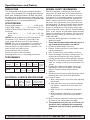
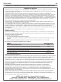
DESCRIPTION
This Submersible Sump Pump is designed for home
sumps. Unit is equipped with a 3-prong grounding-type
power cord. Shaded-pole motor is oil filled and sealed
for cooler running. Sleeve bearings on motor shaft never
need lubrication. Automatic reset thermal protection. Not
designed for use as a swimming pool drainer.
SPECIFICATIONS
Power supply required ...........................115V, 60 HZ.
Liquid Temp. Range ................32°F to 70°F(0°-21°C)
Individual Branch Circuit Required (min.) ....15 Amps
Discharge:
Check Valve.......................1-1/4" slip / 1-1/2" slip
Hose............................................................1-1/4"
NOTICE: Do not reduce size of discharge pipe or
hose below 1-1/4” diameter. If discharge is too
small, pump will overheat and fail prematurely.
NOTICE: This unit is not designed as a waterfall or
fountain pump, or for applications involving salt
water or brine! Use with waterfalls, fountains, salt
water or brine will void warranty.
Pump water only with this pump.
Do not use where water recirculates.
Not designed for use as a swimming pool drainer.
PERFORMANCE
ELECTRICAL & SWITCH SPECIFICATIONS
GENERAL SAFETY INFORMATION
Electrically powered sump pumps normally give
many years of trouble-free service when correctly
installed, maintained, and used. However, unusual
circumstances (interruption of power to the pump,
dirt/debris in the sump, flooding that exceeds the
pump’s capacity, electrical or mechanical failure in
the pump, etc.) may prevent your pump from func-
tioning normally. To prevent possible water damage
due to flooding, consult your retailer about a sec-
ondary AC sump pump, a DC backup sump pump,
and/or a high water alarm. See the “Troubleshooting
Chart” in this manual for information about common
sump pump problems and remedies. For more infor-
mation, see your retailer or call customer service at
1-800-468-7867.
1. Know the pump application, limitations, and
potential hazards.
2. Do not use this pump in water with fish present. If
any oil leaks out of the motor it can kill fish.
3. Disconnect power before servicing.
4. Release all pressure within system before servic-
ing any component.
5. Drain all water from system before servicing.
6. Secure discharge line before starting pump. An
unsecured discharge line will whip, possibly
causing personal injury and/or property damage.
7. Check hoses for weak or worn condition before
each use, making certain that all connections are
secure.
8. Periodically inspect sump, pump and system
components. Keep free of debris and foreign
objects. Perform routine maintenance as
required.
9. Provide means of pressure relief for pumps whose
discharge line can be shut-off or obstructed.
10. Personal Safety:
a. Wear safety glasses at all times when working
with pumps.
b. Keep work area clean, uncluttered and prop-
erly lighted – replace all unused tools and
equipment.
c. Keep visitors at a safe distance from work
area.
d. Make workshop child-proof – with padlocks,
master switches, and by removing starter
keys.
11. When wiring an electrically driven pump, follow
all electrical and safety codes that apply.
12. This equipment is only for use on 115 volt (sin-
gle phase) and is equipped with an approved
3-conductor cord and 3-prong, grounding-type
plug.
GPH (LPH) AT TOTAL FEET (M) OF LIFT
51015
Series HP (1.5m) (3m) (4.6m)
CAPACITY GALLONS(L)/HOUR
2944RP
1/2
3200 2700 2000 24 Ft.
(12 113) (10 220) (7 571) (7.3M)
No flow
at height
shown
below
Individual
Motor Branch *Switch Setting
Full Load Circuit in inches (mm)
Series HP Amps Req.(Amps) On Off
2944RP 1/2 5.5 15 8"(203) 3.5"(89)

For parts or assistance, call Simer Customer Service at 1-800-468-7867 / 1-800-546-7867
Installation and Operation 3
To reduce risk of electric
shock, pull plug before ser-
vicing. This pump has not been investigated for
use in swimming pool areas. Pump is supplied
with a grounding conductor and grounding-type
attachment plug. Be sure it is connected only to
a properly grounded grounding-type receptacle.
Where a 2-prong wall receptacle is encoun-
tered, it must be replaced with properly
grounded 3-prong receptacle installed in accor-
dance with codes and ordinances that apply.
13. All wiring should be performed by a qualified
electrician.
14. Make certain power source conforms to require-
ments of your equipment.
15. Protect electrical cord from sharp objects, hot
surfaces, oil, and chemicals. Avoid kinking cord.
Replace or repair damaged or worn cords imme-
diately.
16. Do not touch an operating motor. Modern motors
can operate at high temperatures.
17. Do not handle pump or pump motor with wet
hands or when standing on wet or damp surface,
or in water.
Hazardous voltage can shock,
burn or kill. If your basement
has water or moisture on floor, do not walk on wet
area until all power has been turned off. If shut-off
box is in basement, call electric company or hydro
authority to shut-off service to house, or call your
local fire department for instructions. Remove
pump and repair or replace. Failure to follow this
warning can result in fatal electrical shock.
Do not lift pump by power cord.
INSTALLATION
1. Install pump in sump pit with minimum diameter
of 10" (254mm). Sump depth should be 10”
(254mm). Construct sump pit of tile, concrete,
steel or plastic. Check local codes for approved
materials and for proper installation.
2. Install pump in pit so that switch operating
mechanism has maximum possible clearance.
3. Pump should not be installed on clay, earth or
sand surfaces. Clean sump pit of small stones
and gravel which could clog pump. Keep pump
inlet screen clear.
NOTICE: Do not use ordinary pipe joint com-
pound on plastic pipe. Pipe joint compound can
attack plastics.
Risk of flooding. If the flexi-
ble discharge hose is used,
make sure pump is secured in sump to prevent
movement. Failure to secure pump may allow
pump movement, switch interference and pre-
vent pump from starting or stopping.
4. Power Supply: Pump is designed for 115 V., 60
Hz., operation and requires a minimum 15 amp
individual branch circuit. Both pump and switch
are supplied with 3-wire cord sets with ground-
ing-type plugs. Switch plug is inserted directly
into outlet and pump plug inserts into opposite
end of switch plug.
Pump should always be elec-
trically grounded to a suit-
able electrical ground such as a grounded
water pipe or a properly grounded metallic
raceway, or ground wire system. Do not cut off
round ground pin.
5. If pump discharge line is exposed to outside sub-
freezing atmosphere, portion of line exposed
must be installed so any water remaining in pipe
will drain to the outfall by gravity. Failure to do
this can cause water trapped in discharge to
freeze which could result in damage to pump.
6. After piping, check valve and float switch have
been installed, the unit is ready for operation.
7. Check the pump operation by filling sump with
water and observing pump operation through one
complete cycle. For switch settings see the Electrical
and Switch Specifications chart on Page 2.
Failure to make this opera-
tional check may lead to
improper operation, premature failure, and
flooding.
TM
E.I. DuPont De Nemours and Company Corporation, Delaware.

For parts or assistance, call Simer Customer Service at 1-800-468-7867 / 1-800-546-7867
OPERATION
Risk of electric shock. Do not
handle a pump or pump motor
with wet hands or when standing on wet or damp
surface, or in water.
1. Shaft seal depends on water for lubrication. Do
not operate pump unless it is submerged in
water as seal may be damaged if allowed to run
dry.
2. Motor is equipped with automatic reset thermal
protector. If temperature in motor should rise
unduly, switch will cut off all power before dam-
age can be done to motor. When motor has
cooled sufficiently, switch will reset automatically
and restart motor. If protector trips repeatedly,
pump should be removed and checked as to
cause of difficulty. Low voltage, long extension
cords, clogged impeller, very low head or lift, or
a plugged or frozen discharge pipe, etc., could
cause cycling.
3. Pump will not remove all water. If operating a
pump manually, and suddenly no water comes
out of the discharge hose, shut off the unit
immediately. The water level is probably very low
and the unit has broken prime.
Risk of electric shock. Before
attempting to check why unit
has stopped operating, disconnect power from
unit.
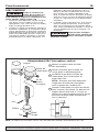
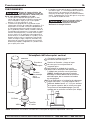
Operation 4
2
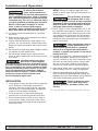
Slip the float and then the rod stop
onto the rod past the second nib.
1
Mount the bracket on the switch
housing.
4
Attach the switch to the discharge pipe
as shown. The bottom of the bracket should
be 7-1/4” above the top of the volute for
correct on/off points (see below).
Vertical Switch Replacement
Rod
Rod Stop
Float
Bracket
Bracket
Mounting
Screws
Switch
Housing
Pin
3
Insert the rod assembly up into the
switch housing and lock into place
with the pin.
NOTICE: Be sure the pin holds the
rod in the switch housing or the pump
will not shut off.
7-1/4”
NOTICE: See instructions included with replacement switch, Part Number FPS17-66.

For parts or assistance, call Simer Customer Service at 1-800-468-7867 / 1-800-546-7867
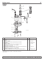
Repair Parts 5
7
6
5
4
2
1
3
10
11
8
12
9
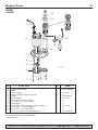
6131 1209
MODEL
2944RP
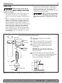
**If motor fails, replace entire pump.
† Standard hardware item; purchase locally.
• Not illustrated
Key
No. Part Description Qty. 2944RP
1 Power Cord Assembly 1 PS117-54-TSU
2 Motor 1 **
3 Volute (Upper) 1 PS1-31P
4 Screw, #8-32x5/8” Phillips Pan Head 4 †
5 Impeller 1 RP0000911A
6 Volute (Lower) 1 PS1-30P
7 Screw, #8-16x1/2” Lg. Pan Head 7 †
8 1-1/4” NPT x 1-1/4” Slip Adapter 1 †
9 Switch Clamp 1 †
10 Vertical Float Switch Assembly (includes Key No. 9) 1 FPS17-66
11 1-1/2” Slip x 1-1/4” NPT Adapter 1 †
12 1-1/4” NPT x 1-1/4” Hose Barb 1 †
• 1-1/4” x 24’ Hose Kit (includes Key No. 12) 1 FP0012-6U-P2

For parts or assistance, call Simer Customer Service at 1-800-468-7867 / 1-800-546-7867
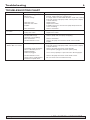
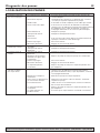
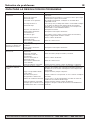
Troubleshooting 6
SYMPTOM PROBABLE CAUSE(S) CORRECTIVE ACTION
Pump won’t start or run. Pump is not plugged in. Check and see if pump is plugged in to a proper outlet.
Blown fuse. If blown, replace with fuse of proper size.
Low line voltage. If voltage under recommended minimum, check size of wiring
from main switch on property. If OK, contact power company
or hydro authority.
Defective motor. Replace pump.
Defective float switch. Replace float switch.
Impeller. If impeller won’t turn, remove lower pump body and locate
source of binding.
Float obstructed. Remove obstruction.
Pump starts and stops Backflow of water from piping. Install or replace check-valve.
too often.
Faulty float switch. Replace float switch.
Pump won’t shut off. Defective float switch. Replace float switch.
Restricted discharge Remove pump and clean pump and piping.
(obstacle or ice in piping).
Float obstructed. Remove obstruction.
Restricted intake screen. Remove the pump and clean the intake screen and the
impeller.
Pump operates but Low line voltage. If voltage under recommended minimum, check size of wiring
delivers little or no water. from main switch on property. If OK, contact power company
or hydro authority.
Something caught in impeller. Remove the pump and clean out the impeller.
Worn or defective parts or Clean impeller if plugged; otherwise replace pump.
plugged impeller.
Vent hole plugged. Use a nail or paperclip to open vent hole in discharge pipe.
Restricted intake screen. Remove the pump and clean out the intake screen.
Check valve is installed either Be sure check valve is installed correctly.
backward or upside down.
TROUBLESHOOTING CHART

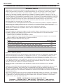
Warranty 7
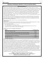
RETAIN ORIGINAL RECEIPT FOR YOUR RECORDS.
LIMITED WARRANTY
SIMER warrants to the original consumer purchaser (“Purchaser” or “You”) of its products that they are free from
defects in material and workmanship for a period of twelve (12) months from the date of the original consumer purchase.
If, within twelve (12) months from the original consumer purchase, any such product shall prove to be defective, it shall
be repaired or replaced at SIMER’s option, subject to the terms and conditions set forth below. The original purchase
receipt and product warranty information label are required to determine warranty eligibility. Eligibility is based on
purchase date of original product – not the date of replacement under warranty. The warranty is limited to repair or
replacement of product only – Purchaser pays all removal, installation, labor, shipping, and incidental charges.
For parts or troubleshooting assistance, DO NOT return product to your retail store. Contact SIMER Customer Service
at 1-800-468-7867 / 1-800-546-7867.
Claims made under this warranty shall be made by returning the product (except sewage pumps, see below) to the
retail outlet where it was purchased immediately after the discovery of any alleged defect. SIMER will subsequently
take corrective action as promptly as reasonably possible. No requests for service will be accepted if received more
than 30 days after the warranty expires.
Warranty does not apply to products used in commercial/rental applications.
SEWAGE PUMPS
DO NOT return a sewage pump (that has been installed) to your retail store. Contact SIMER Customer Service. Sewage
pumps that have seen service and been removed carry a contamination hazard with them.
If your sewage pump has failed:
• Wear rubber gloves when handling the pump;
• For warranty purposes, return the pump’s cord tag and original receipt of purchase to the retail store;
• Dispose of the pump according to local disposal ordinances.
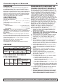
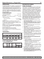
Exceptions to the Twelve (12) Month Limited Warranty
Product Warranty Period
BW85P, CM10, CMK, M40, M40P 90 days
2300, 2310, 2330, 2520ULST, 2943, 2955, 2956, 2957, 2960, 5023SS, A5500 2 Years
4” Submersible Well Pumps, 2945, 2958, 2975PC, 2985, 3075SS, 3983, 3984 3 Years
Pre-Charge Water System Tank, 3985, 3986 5 Years
3963, 3988, 3995, 3997 Lifetime
General Terms and Conditions
You must pay all labor and shipping charges necessary to replace product covered by this warranty. This warranty
does not apply to the following: (1) acts of God; (2) products which, in SIMER’s sole judgement, have been subject to
negligence, abuse, accident, misapplication, tampering, or alteration; (3) failures due to improper installation, operation,
maintenance or storage; (4) atypical or unapproved application, use or service; (5) failures caused by corrosion, rust or
other foreign materials in the system, or operation at pressures in excess of recommended maximums.
This warranty sets forth SIMER’s sole obligation and purchaser’s exclusive remedy for defective products.
SIMER SHALL NOT BE LIABLE FOR ANY CONSEQUENTIAL, INCIDENTAL, OR CONTINGENT DAMAGES WHATSOEVER.
THE FOREGOING WARRANTIES ARE EXCLUSIVE AND IN LIEU OF ALL OTHER EXPRESS AND IMPLIED WARRANTIES,
INCLUDING BUT NOT LIMITED TO THE IMPLIED WARRANTIES OF MERCHANTABILITY AND FITNESS FOR A PARTICU-
LAR PURPOSE. THE FOREGOING WARRANTIES SHALL NOT EXTEND BEYOND THE DURATION PROVIDED HEREIN.
Some states do not allow the exclusion or limitation of incidental or consequential damages or limitations on how long
an implied warranty lasts, so the above limitations or exclusions may not apply to You. This warranty gives You specific
legal rights and You may also have other rights which vary from state to state.
SIMER • 293 Wright St., Delavan, WI U.S.A. 53115
Phone: 1-800-468-7867 / 1-800-546-7867 • Fax: 1-800-390-5351
Web Site: http://www.simerpumps.com
Page is loading ...
Page is loading ...

2
Slip the float and then the rod stop
onto the rod past the second nib.
1
Mount the bracket on the switch
housing.
4
Attach the switch to the discharge pipe
as shown. The bottom of the bracket should
be 7-1/4” above the top of the volute for
correct on/off points (see below).
Vertical Switch Replacement
Rod
Rod Stop
Float
Bracket
Bracket
Mounting
Screws
Switch
Housing
Pin
3
Insert the rod assembly up into the
switch housing and lock into place
with the pin.
NOTICE: Be sure the pin holds the
rod in the switch housing or the pump
will not shut off.
7-1/4”
For parts or assistance, call Simer Customer Service at 1-800-468-7867 / 1-800-546-7867
Pour les services des pièces ou d'assistance, appeler le service à la clientèle Simer en composant le 1 (800) 468-7867 / 1(800) 546-7867
FONCTIONNEMENT
Risque de secousses élec-
triques. Ne pas toucher à la
pompe ni au moteur de la pompe lorsqu'on a les
mains humides ou lorsqu'on se tient debout sur une
surface mouillée, humide ou dans l'eau.
1. Le joint de l'arbre dépend de l'eau pour son grais-
sage. Ne pas utiliser la pompe si elle n'est pas
immergée dans l'eau, sinon son joint sera endom-
magé si la pompe fonctionne à sec.
2. Le moteur est équipé d'un protecteur thermique à
réarmement automatique. Si la température devait
s'élever anormalement, le disjoncteur interrompra
automatiquement l'arrivée de courant avant que le
moteur soit endommagé. Lorsque le moteur aura
suffisamment refroidi, le disjoncteur se réarmera
automatiquement et le moteur redémarrera. Si le
protecteur se déclenche constamment, sortir la
pompe du puisard et en déterminer la cause. Une
basse tension, des cordons prolongateurs trop
longs, un impulseur bouché, une hauteur de refoule-
ment très basse ou un tuyau de refoulement bouché
ou gelé, etc. risquent de causer un fonctionnement
intermittent.
3. La pompe n'aspirera pas toute l'eau. Si on fait fonc-
tionner la pompe manuellement, et que brusque-
ment l'eau ne coule plus par son tuyau de refoule-
ment, arrêter immédiatement la pompe. Le niveau de
l'eau est probablement très bas et la pompe s'est
désamorcée.
Risque de chocs électriques.
Avant de vérifier pourquoi cette
pompe a cessé de fonctionner, interrompre le courant
parvenant à la pompe.
Fonctionnement 10
Support
Remplacement de l’interrupteur vertical
Monter le support dans le boîtier
de l’interrupteur.
Glisser le flotteur, puis la butée sur
la tige après la deuxième pointe.
Introduire la tige dans le boîtier de
l’interrupteur, puis le verrouiller en
place avec l’axe.
NOTA : S’assurer que l’axe retient bien
la tige dans le boîtier de l’interrupteur,
sinon la pompe ne s’arrêtera pas.
Attacher l’interrupteur au tuyau de refoule-
ment, comme il est illustré. Le dessous du
support devrait être situé à 7-1/4 po au-
dessus de la partie supérieure de la volute
pour fixer les bons points marche/arrêt
(voir ci-dessous).
Boîtier de
l’interrupteur
Vis de
fixation
du support
Axe
Tige
Flotteur
Butée
de tige
NOTA : Se reporter aux instructions incluses avec l’interrupteur de rechange, numéro de pièce FPS17-66.
Page is loading ...
Page is loading ...
Page is loading ...
Page is loading ...
Page is loading ...

For parts or assistance, call Simer Customer Service at 1-800-468-7867 / 1-800-546-7867
Funcionamiento 16
Para refacciones o asistencia, llame a Simer Servicios al Cliente al: 1 800 468-7867 / 1 800 546-7867
FUNCIONAMIENTO
Riesgo de choque eléctrico. No
manipule la bomba o el motor de
la bomba con las manos mojadas o cuando esté para-
do en suelo húmedo, mojado o en el agua.
1. La junta del eje depende del agua para su lubri-
cación. No haga funcionar la bomba a menos que
esté sumergida en agua ya que la junta puede
dañarse si se hace trabajar en seco.
2. El motor está equipado con un protector contra
sobrecargas térmicas de reposición automática. Si la
temperatura en el motor se elevara indebidamente,
el interruptor puede cortar toda la energía antes de
que se produzca daño al motor. Cuando el motor se
ha enfriado suficientemente, el interruptor se reposi-
cionará automáticamente y el motor volverá a pon-
erse en marcha. Si el protector se desengancha en
forma continua, la bomba debe ser sacada y revisa-
da para verificar cual es el problema. Baja tensión,
cables de alargue largos, impulsor atascado, muy
baja altura de aspiración o elevación o una tubería
de descarga tapada o congelada, etc. pueden hacer
que se pase por el ciclo.
3. La bomba no saca toda el agua. La bomba no aspi-
rará toda el agua. Si se está operando la bomba en
forma manual y de repente no sale agua de la
manguera de descarga, apague la unidad inmediata-
mente. Probablemente el nivel del agua es muy bajo
y la unidad ha dejado de cebar.
Riesgo de choque eléctrico.
Antes de intentar revisar
porque la bomba ha dejado de funcionar,
desconecte la energía eléctrica.
2
Slip the float and then the rod stop
onto the rod past the second nib.
1
Mount the bracket on the switch
housing.
4
Attach the switch to the discharge pipe
as shown. The bottom of the bracket should
be 7-1/4” above the top of the volute for
correct on/off points (see below).
Vertical Switch Replacement
Rod
Rod Stop
Float
Bracket
Bracket
Mounting
Screws
Switch
Housing
Pin
3
Insert the rod assembly up into the
switch housing and lock into place
with the pin.
NOTICE: Be sure the pin holds the
rod in the switch housing or the pump
will not shut off.
7-1/4”
Ménsula
Reemplazo del interruptor vertical
Coloque la ménsula sobre la
envoltura del interruptor
Deslice el flotador y luego el tope
de vara por la vara pasando el
segundo pico.
Introduzca la unidad de la varilla
dentro de la envoltura del interruptor
y trábela en posición con el pasador.
AVISO: Asegúrese de que el pasador
sostenga la varilla dentro de la envoltura
del interruptor, de lo contrario la bomba
no se apagará.
Fije el interruptor a la tubería de descarga
según se ilustra. La parte inferior de la
ménsula deberá estar a 7-1/4” por encima
de la parte superior de la voluta para que
los puntos de encender/apagar (on/off)
queden en la posición correcta (ver abajo)
Envoltura
del
interruptor
Tornillos
de montaje
de la
ménsula
Pasador
Varilla
Flotador
Tope de
la varilla
AVISO: Consulte las instrucciones incluidas con el interruptor de repuesto, Repuesto No. FPS17-66.
Page is loading ...
Page is loading ...
Page is loading ...
Page is loading ...
-
 1
1
-
 2
2
-
 3
3
-
 4
4
-
 5
5
-
 6
6
-
 7
7
-
 8
8
-
 9
9
-
 10
10
-
 11
11
-
 12
12
-
 13
13
-
 14
14
-
 15
15
-
 16
16
-
 17
17
-
 18
18
-
 19
19
-
 20
20


Ask a question and I''ll find the answer in the document
Finding information in a document is now easier with AI
in other languages
- français: Simer Pumps 2944RP Manuel utilisateur
- español: Simer Pumps 2944RP Manual de usuario
Related papers
Other documents
-
Simer 2944RP User manual
-
-
-
Simer 2905-04 Owner's manual
-
-
Simer 5905E User manual
-
-
Pentair 3995 Owner's manual
-
Pentair 2975PC Owner's manual
-
Simer 3075SS Owner's manual