Page is loading ...

Installation
Instructions
QuickTwist
™
1 Stage Drinking Water Filtration System
& Direct Flow 1 Stage Drinking Water Filtration System
Instrucciones de instalación
Sistema de filtrado de agua potable de 1 etapa QuickTwist
™
y dirija el sistema de la
filtración del agua potable de la etapa del flujo 1
Model Series WFQT13000 and WFQT13500
Serie del modelo WFQT13000 y WFQT13500
Water Filtration
V4.0

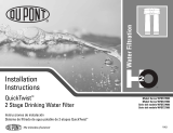
Package Contents
Installation Instructions
QuickTwist
™
1 Stage Drinking Water Filtration System
Parts & Hardware Included
A
Filter System Head with Built-in Bracket
B QuickTwist
™
Filter
C Mounting Screws
D Faucet for Filtered Water
E Black Rubber Gasket
F Metal Lock Washer
G Faucet Stem Nut
H Kitchen Faucet Adapter
I Insert
J Ferrule
K Compression Nut
L 1/4" Plastic Tubing
Tools & Materials Required
n Phillips Screwdriver
n 1/8" Drill Bit
n Center Punch
n Adjustable Wrench
n Utility Knife
n File
n Tape Measure
n Safety Glasses
n Masking Tape
n Newspaper or Towels
n Pencil
n Pan or Bucket
n Compression Cap (Optional-For Kitchen Faucet
Spray Hose Connector)
Optional Materials
n Drill with 1/4" & 9/16" or 5/8" Drill Bits
n Hollow-Wall Anchor Bolts or Toggle Bolts
n Hacksaw
n Plumber’s Tape
For installations in Massachusetts, the Commonwealth of Massachusetts Plumbing Code CMR248 shall be adhered to.
www.waterfiltration.DuPont.com
Protect Plus, LLC n Hickory, NC 28601 USA
866-709-2086 Toll Free
For Service Requests & Product Information
Hours of Operation: 24 Hours/Day, 7 Days/Week
800-441-7515
For Safety & Health Questions
Information & Assistance
A
B
CH
K
L
J
I
G
F
E
D
System Head with
Built-in Bracket
DuPont Part No. WFAH100
QuickTwist™
Filter
Faucet for
Filtered Water
Black
Rubber Gasket
Metal Lock Washer
Faucet Stem Nut
Insert
Ferrule
Compression Nut
Faucet Connector Set
DuPont Part No. WFAF600
1/4" Plastic Tubing
DuPont Part No. WFAF300 (6 Feet)
KFA-Kitchen Faucet Adapter
1/2" NPTF to 1/4" Tube
DuPont Part No. WFAF400
Mounting Screws
DuPont Part No. WFAS300
(Package of 2)

Package Contents
Installation Instructions
QuickTwist
™
Direct Flow 1 Stage Drinking Water Filtration System
Parts & Hardware Included
A
Filter System Head with Built-in Bracket
B QuickTwist
™
Filter
C Mounting Screws
D 3/8” Male OD Adapter
E 3/8” Female OD Adapter
F 1/4” Plastic Tubing
Tools & Materials Required
n Phillips Screwdriver
n 1/8" Drill Bit
n Center Punch
n Adjustable Wrench
n Utility Knife
n File
n Tape Measure
n Safety Glasses
n Masking Tape
n Newspaper or Towels
n Pencil
n Pan or Bucket
n Compression Cap (Optional-For Kitchen Faucet
Spray Hose Connector)
Optional Materials
n Drill with 1/4" & 9/16" or 5/8" Drill Bits
n Hollow-Wall Anchor Bolts or Toggle Bolts
n Hacksaw
n Plumber’s Tape
For installations in Massachusetts, the Commonwealth of Massachusetts Plumbing Code CMR248 shall be adhered to.
www.waterfiltration.DuPont.com
Protect Plus, LLC n Hickory, NC 28601 USA
866-709-2086 Toll Free
For Service Requests & Product Information
Hours of Operation: 24 Hours/Day, 7 Days/Week
800-441-7515
For Safety & Health Questions
Information & Assistance
A
B
C
F
1/4" Plastic Tubing
DuPont Part No. WFAF300 (6 Feet)
Mounting Screws
DuPont Part No. WFAS300
(Package of 2)
S
yst
e
m
H
e
a
d
wi
t
h
B
u
i
l
t
-i
n
B
ra
c
k
e
t
D
u
Po
n
t
Pa
rt
No
. WFA
H
100
Q
u
i
c
k
Twi
st
™
Fi
l
t
e
r
D
E
3/8" Male
OD Adapter
3/8" Female
OD Adapter

Proper Installation
Please read all instructions, specifications, and precautions before installing and using your water filter system.
Precautions:
For cold water use only.
After prolonged periods of non-use (such as during a vacation), it is recommended that the Filter System be flushed thoroughly. Let water
run for 10 minutes before using.
The QuickTwist™ Filter used with this Filter System has a limited service life. Changes in taste, odor, and/or flow of the water being
filtered indicate that the filter should be replaced.
Before You Begin
n Check under the sink to locate a solid wall surface to mount the Filter System.
NOTE: The Filter System must be mounted in a vertical position.
n Locate the cold water pipe under your sink and observe if it is a flexible hose or a rigid pipe (ex: plastic, metal, copper). Rigid pipes
may require cutting in order to make adequate space to install the Kitchen Faucet Adapter (see Step 2). Also determine if you have
all appropriate fasteners and adapters to fit your plumbing.
n Consult your local plumbing codes and install accordingly.
n If you plan to install your QuickTwist
TM
WFDW13000 Series direct to your kitchen faucet please skip to page 10.
n If you purchased a QuickTwist
TM
WFDW13500 Series and you plan to direct connect to your kitchen faucet please skip to page 10.
STEP 1
Turn Off the Main Water Supply Line
1 Locate the cold water shut-off valve under the sink. Turn off the cold water supply to the existing kitchen sink.
NOTE: If uncertain about which line supplies the cold water, turn on the hot water to the faucet. Allow the water to heat up and carefully
feel the pipes under the sink. The pipe that remains cool to the touch is the cold water supply.
2 Turn on the cold water faucet on the kitchen sink to release pressure and allow water to completely drain from the line.
This filter must be protected
from freezing, which can
cause cracking of the filter
and water leakage.
CAUTION
Because of the product’s limited service life and to prevent costly repairs or possible water damage, we strongly
recommend that the head of the filter be replaced every ten years. If the head of the filter has been in use for
longer than this period, it should be replaced immediately. Date the top of any new head to indicate the next
recommended replacement date.
CAUTION
RIGID PIPE INSTALLATION
FLEXIBLE HOSE INSTALLATION
KITCHEN FAUCET
F
AUCET FOR
F
ILTERED WATER
H
OT WATER
VALVE
C
OLD WATER
VALVE
KITCHEN FAUCET
FAUCET FOR
FILTERED WATER
HOT WATER
VALVE
COLD WATER
VALVE
1
COLD WATER
VALVE
4
WFQT13000 & WFQT13500 Series

STEP 2 Mount the Faucet for Filtered Water
NOTE: The Faucet for Filtered Water in this package is designed to fit a 9/16" hole. Most standard sinks come with 1-3/8" or 1-1/2" diameter
water sprayer holes that can be used for mounting the Faucet. If the pre-drilled holes cannot be used or are not in the desired position, a new
hole must be drilled using either a 9/16" or 5/8" drill bit to accommodate the Faucet. The Faucet for Filtered Water base should be positioned
securely on a flat surface with adequate space for proper function. Consider convenience and appearance of the faucet before installation.
IF YOUR SINK DOES NOT HAVE A WATER SPRAYER HOLE, GO TO
1. IF YOUR SINK DOES HAVE A WATER SPRAYER HOLE, GO TO 4.
1 In order to prevent parts and materials from falling down the drain, line the sink with newspaper or a towel.
2 Apply masking tape to the area to be drilled in order to prevent scratching the sink surface or countertop if the drill bit slips
during operation.
3 Using a center punch, mark the drill hole. Use the 1/4" drill bit to make a pilot hole. Then use the 9/16" or 5/8" drill bit to drill the final
hole. Drill completely through the sink or countertop and smooth the rough edges with a file.
NOTE: Make sure that the Faucet for Filtered Water is assembled. The Faucet for Filtered Water Spout should be inserted into the Faucet for
Filtered Water Body and the retaining nut should be tightened until snug.
4 Guide the Black Rubber Gasket E onto the threaded Faucet for Filtered Water Stem. Slip the threaded Faucet Stem into the sink or
countertop hole. Make sure the Faucet for Filtered Water sits flat on top of the sink or countertop surface.
5 From underneath the sink, slide the Metal Lock Washer F up the Faucet for Filtered Water Stem. Then screw the plastic Faucet
Stem Nut
G all the way up the Faucet Stem until it is flush with the Metal Lock Washer. Screw until it is slightly snug and check
to make sure the faucet spout is in the proper position. Using fingers, tighten the nut to secure the Faucet for Filtered Water to
the sink.
NOTE: Do not tighten the Faucet for Filtered Water Stem Nut with pliers as it may strip the Faucet Stem threads.
1
2
E
F
G
Safety glasses and a respirator are
recommended for this process, as it
may produce dust that can cause
severe irritation if it is inhaled or
comes in contact with eyes.
CAUTION
DO NOT DRILL THROUGH AN ALL-PORCELAIN OR CAST IRON SINK. If installing on an all-porcelain
or cast iron sink, the faucet must be mounted in a pre-drilled sprayer hole or through the countertop
next to the sink. If the countertop must be drilled, make certain that the area below the drilling
location is free of wiring and pipes. Also, make sure that there is sufficient room to make the proper
connections to the bottom of the faucet mount. DO NOT DRILL THROUGH COUNTER TOPS MORE
THAN 1" IN THICKNESS OR COUNTERTOPS MADE OF TILE, MARBLE, GRANITE OR SIMILAR
SUBSTANCE. Consult with a plumber or the countertop manufacturer for assistance.
CAUTION
FAUCET FOR
F
ILTERED WATER
S
POUT
BASE
V4.0
5
WFQT13000 & WFQT13500 Series

4
STEP 3
Install the Kitchen Faucet Adapter
NOTE: The Kitchen Faucet Adapter is designed to fit 1/2" NPTF supply threads.
1 Locate the cold water shut-off valve under the sink. Turn off the cold water supply to the sink.
NOTE: If uncertain about which line supplies the cold water, turn on the hot water to the faucet. Allow the water to heat up and carefully
feel the pipes under the sink. The pipe that remains cool to the touch is the cold water supply.
2 Turn on the kitchen faucet to release pressure and allow water to completely drain from the line.
3 Disconnect the cold water line from the 1/2" threaded stem on the bottom of the kitchen faucet.
NOTE: If rigid plumbing pipe (metal or plastic) is used, you may need to shorten the pipe using a hacksaw to accommodate the
Kitchen Faucet Adapter.
4 Holding the Kitchen Faucet Adapter H in an upright position (see diagram), screw onto the threaded faucet stem.
5 Screw the cold water supply line to the male threads of the Kitchen Faucet Adapter using the nut that was connecting the cold
water line to the kitchen faucet previously. For a secure fit, tighten the nut using an adjustable wrench.
6 If you have replaced your sprayer with the Faucet for Filtered Water be sure to cap off the sprayer outlet from the kitchen faucet.
Most faucets will require a compression cap to seal and prevent leaks.
STEP 4
Mount the System Head
1 Choose an easy-to-access area under the sink to mount the Filter System.
NOTE: To allow adequate space for filter changes, allow a minimum clearance of 4-6" below the QuickTwist
™
Filter. The Filter System
must be mounted in a vertical position.
NOTE: Mount the Filter System to a solid cabinet wall or wall. If a solid surface is not available, use hollow-wall anchor bolts or toggle
bolts (not included) to secure to the wall.
2 Remove the cap from the top of the System Head A. Using the Built-in Bracket on the back of the System Head or the template
provided on the back of this booklet, mark the holes for the Mounting Screws
C on the wall surface.
3 Using a 1/8" drill bit, drill two pilot holes for the Mounting Screws. Insert Mounting Screws into the wall with a Phillips screwdriver,
leaving approximately 3/8" of each Mounting Screw exposed.
4 Hang the System Head on the eyes of the bracket and replace the System Head cap.
3
X
X
H
2
1
4
3
5
3
2
Be sure that all electrical appliances and outlets are turned off at the
circuit breaker before working in cabinet area.
WARNING
Please wear safety glasses to protect
eyes when drilling.
CAUTION
A
RIGID PIPE INSTALLATION
4-6"
KITCHEN FAUCET
HOT WATER
VALVE
COLD WATER
VALVE
INLET OUTLET
6
WFQT13000 & WFQT13500 Series

STEP 5
Install 1/4" Plastic Tubing for Water Supply Line from
Kitchen Faucet Adapter to System Head Inlet
1 Determine the length of 1/4" Plastic Tubing L that will be necessary to connect the System Head Inlet to the Kitchen Faucet
Adapter
H. Make sure to allow enough Plastic Tubing to prevent kinking in the line.
2 Cut the 1/4" Plastic Tubing squarely on both ends.
3 Wet one end of the 1/4" Plastic Tubing with water and push it into the Kitchen Faucet Adapter approximately 5/8" until it stops.
NOTE: Do not bend or crimp 1/4" Plastic Tubing when inserting.
4 Wet the other end of the 1/4" Plastic Tubing with water and push it into the System Head Inlet approximately 5/8" until it stops.
NOTE: The 1/4" Plastic Tubing does not need to be disconnected for general routine maintenance and filter replacement. However,
Plastic Tubing may be easily disconnected if necessary. Simply turn off the water supply to the Filter System and press in the grey collar
around the fitting while pulling the Plastic Tubing out with the other hand.
STEP 6
Install 1/4" Plastic Tubing for Water Supply Line from
System Head Outlet to Faucet
1 Determine the length of 1/4" Plastic Tubing L that will be necessary to connect the System Head Outlet to the threaded Faucet
Stem. Make sure to allow enough Plastic Tubing to prevent kinking in the line.
2 Cut the 1/4" Plastic Tubing squarely on both ends.
3 Wet one end of the 1/4" Plastic Tubing with water and push it into the System Head Outlet until it stops.
4 Gently slide the plastic Compression Nut down G (thread side up) over the tubing. Follow with the plastic Ferrule J, making sure
that the Ferrule is in the proper position with the larger opening on the bottom (going into the nut). Place the plastic Insert
I into
the end of the 1/4" Plastic Tubing.
5 Firmly push the 1/4" Plastic Tubing into the end of the threaded Faucet Stem. Hand-tighten the plastic Compression Nut onto the
threads. Tighten with an adjustable wrench approximately 1/2 turn.
NOTE: Do not bend or crimp 1/4" Plastic Tubing when inserting. Do not over tighten the Compression Nut.
6
4
5
G
J
I
FAUCET FOR
FILTERED WATER
3
1/4" PLASTIC TUBING
INLET OUTLET
5
3
4
INLET OUTLET
HOT WATER
V
ALVE
1/4" PLASTIC TUBING
COLD WATER
V
ALVE
5/8"
V4.0
7
WFQT13000 & WFQT13500 Series

STEP 7
Install the QuickTwist
™
Filter
1 Hold the QuickTwist
™
Filter B with the label facing to the left slightly. The two nozzles on top of the QuickTwist
™
Filter should be
toward the back of the QuickTwist
™
Filter. If holding properly, the two extended flanges on top of the QuickTwist
™
Filter should be
out to each side. See Figure 6
1 at right.
2 Lift the QuickTwist
™
Filter straight up into the System Head A until the two nozzles seat into the ports and the two extended flanges
on top of the QuickTwist
™
Filter are fully engaged into the System Head.
3 Turn the QuickTwist
™
Filter counter-clockwise until it stops.
STEP 8
Test the Filter System for Proper Operation
1 Turn on the cold water shut-off valve under the sink.
2 Turn on the new Faucet for Filtered Water D. In order for the Filter System to flush out any air and carbon fines (fine black powder)
from the QuickTwist
™
Filter, allow the water to run for approximately 10 minutes.
3 Check for any leaks between the System Head assembly and Filter; around all fittings; on Kitchen Faucet Adapter H connection;
and on faucet/tubing connection.
If there are leaks between the System Head assembly and the QuickTwist
™
Filter:
n Turn off the cold water shut-off valve to the Filter System and turn on the Faucet for Filtered Water to drain the water and
release pressure.
n Remove the QuickTwist
™
Filter and inspect the O-Rings around the nozzles on top of it. Make sure they are in place and free
from dirt and particles.
n Turn off the Faucet for Filtered Water.
n Replace the QuickTwist
™
Filter by lifting it straight up into the System Head until the two nozzles seat into the ports and the
two extended flanges on top of the QuickTwist
™
Filter are fully engaged into the System Head. Turn the QuickTwist
™
Filter
counter-clockwise until it stops.
n Turn the cold water supply valve back on and turn on the Faucet for Filtered Water.
If there are leaks around the fittings:
n Turn off the cold water shut-off valve to the Filter System to release pressure in the System.
n While pulling the 1/4" Plastic Tubing
L with one hand, press in on the grey collar around the inlet and/or outlet fitting. Check
to make sure that the 1/4" Plastic Tubing is cut squarely and that it is not scratched. If the 1/4" Plastic Tubing is unevenly cut
or scratched, cut off 1/2" to 5/8" and re-install the Plastic Tubing (see Step 5 of Installation Instructions).
n Turn the cold water shut-off valve back on and turn on the Faucet for Filtered Water.
continued to next page
8
1
2
FLEXIBLE HOSE INSTALLATION
7
1
2
3
A
B
HOT WATER
VALVE
COLD WATER
VALVE
KITCHEN FAUCET
FAUCET FOR
FILTERED WATER
V4.0
8
WFQT13000 & WFQT13500 Series

STEP 8
Test the Filter System for Proper Operation (continued)
If there are leaks on the Kitchen Faucet Adapter connection:
n Turn off the cold water shut-off valve to the Filter System to release pressure in the System.
n Locate the Kitchen Faucet Adapter.
• If the 1/4" Plastic Tubing is leaking, follow the previous steps (“If there are leaks around the fittings”).
• If the thread between the Kitchen Faucet Adapter and the kitchen faucet stem is leaking, tighten more securely. If leaking
continues, disconnect the 1/4" Plastic Tubing and remove the Kitchen Faucet Adapter. Wrap the Kitchen Faucet Adapter
and the threaded faucet stem with plumber’s tape and re-install (see Step 2 of Installation Instructions).
• If the thread between the Kitchen Faucet Adapter and the cold water supply line is leaking, tighten more securely. If leaking
continues, disconnect the 1/4" Plastic Tubing and remove the Kitchen Faucet Adapter. Wrap the Kitchen Faucet Adapter
and the cold water supply line with plumber’s tape and re-install (see Step 2 of Installation Instructions).
n Turn the cold water shut-off valve back on and turn on the Faucet for Filtered Water.
If there are leaks on the Faucet for Filtered Water/1/4" Plastic Tubing connection:
n Turn off the cold water shut-off valve to the Filter System to release pressure in the System.
n Loosen and remove the Compression Nut
K on the Faucet for Filtered Water Stem. Check the 1/4" Plastic Tubing to see if it is
cut squarely. Make sure the 1/4" Plastic Tubing is placed firmly into the end of the Faucet Stem; retighten the Compression Nut
securely by hand; then tighten 1/2 turn with an adjustable wrench. If leaking continues, remove the Compression Nut and apply
plumber’s tape to the Faucet for Filtered Water Stem and re-install the Compression Nut.
n Turn the cold water shut-off valve back on and turn on the Faucet for Filtered Water.
‰ If leaks continue, turn off the water supply and call Customer Service or your local plumber.
‰ For Filter Replacement Instructions please see below
QuickTwist
™
Filter Replacement
1 Turn off the cold water shut-off valve to the Filter System A.
2 Turn the QuickTwist
™
Filter B clockwise until it releases. Gently pull down on the used QuickTwist
™
Filter to remove it from the
System Head. Discard the used QuickTwist
™
Filter.
NOTE: Place a pan or bucket under the Filter System to catch any water drips.
3 Hold the new QuickTwist
™
Filter with the label facing to the left slightly. The two nozzles on top of the QuickTwist
™
Filter should
be toward the back of the QuickTwist
™
Filter. If holding properly, the two extended flanges on top of the QuickTwist
™
Filter should
be out to each side.
4 Lift the QuickTwist
™
Filter straight up into the System Head until the two nozzles seat into the ports and the two extended
flanges on top of the QuickTwist
™
Filter are fully engaged into the System Head.
5 Turn the QuickTwist
™
Filter counter-clockwise until it stops.
6 Turn on the cold water shut-off valve and the Faucet for Filtered Water D and check for any leaks. If there are leaks, refer to the
troubleshooting information in Step 7 of the Installation Instructions.
7 Flush water through the Faucet for Filtered Water for approximately 10 minutes to flush out any air and carbon fines
(fine black powder) from the QuickTwist
™
Filter. Check for leaks once more before completion.
12
V4.0
9
WFQT13000 & WFQT13500 Series

STEP 1 -Optional Direct Connect
Turn Off the Main Water Supply Line
1 Locate the cold water shut-off valve under the sink. Turn off the cold water supply to the existing kitchen sink.
NOTE: If uncertain about which line supplies the cold water, turn on the hot water to the faucet. Allow the water to heat up and carefully
feel the pipes under the sink. The pipe that remains cool to the touch is the cold water supply.
2 Turn on the cold water faucet on the kitchen sink to release pressure and allow water to completely drain from the line.
STEP 2
-Optional Direct Connect
Mount the System Head
1 Choose an easy-to-access area under the sink to mount the Filter System.
NOTE: To allow adequate space for filter changes, allow a minimum clearance of 4-6" below the QuickTwist
™
Filter. The Filter System
must be mounted in a vertical position.
NOTE: Mount the Filter System to a solid cabinet wall or wall. If a solid surface is not available, use hollow-wall anchor bolts or toggle
bolts (not included) to secure to the wall.
2 Remove the cap from the top of the System Head A. Using the Built-in Bracket on the back of the System Head or the template
provided on the back of this booklet, mark the holes for the Mounting Screws
C on the wall surface.
3 Using a 1/8" drill bit, drill two pilot holes for the Mounting Screws. Insert Mounting Screws into the wall with a Phillips screwdriver,
leaving approximately 3/8" of each Mounting Screw exposed.
4 Hang the System Head on the eyes of the bracket and replace the System Head cap.
1
COLD WATER
VALVE
Optional Installment Method: Direct connect to Kitchen Faucet
NOTE: Undersink filters reduce water flow. If you wish to maintain unfiltered water flow for dishwashing, etc., we recommend
installing separate Faucet for Filtered Water (DuPont WFFT100 Series).
WFQT13000 & WFQT13500 Series
10
RIGID TUBING INSTALLATION
K
ITCHEN FAUCET
HOT WATER
VALVE
COLD WATER
VALVE
4-6”
FLEXIBLE TUBING INSTALLATION
K
ITCHEN FAUCET
HOT WATER
VALVE
COLD WATER
VALVE
2
Be sure that all electrical appliances and outlets are turned off at the
circuit breaker before working in cabinet area.
WARNING
Please wear safety glasses to protect
eyes when drilling.
CAUTION
V4.0
2
3
A
INLET OUTLET

STEP 3
-Optional Direct Connect
Connect Water Lines
FOR RIGID TUBING:
1 Disconnect the bottom of the cold water plumbing line from the shut-off valve and gently bend the plumbing line for access to the
lower line fitting.
2 Screw the 3/8" Male OD Adaptor D onto the compression fitting on the lower end of the plumbing line.
3 Screw the 3/8" Female OD Adaptor E onto the cold water shut-off valve outlet port.
FOR FLEXIBLE TUBING:
1 Disconnect the bottom of the cold water plumbing line from the shut-off valve.
2 Screw the 3/8" Male OD Adaptor D onto the existing nut on the lower end of the flexible hose.
3 Screw the 3/8" Female OD Adaptor E onto the cold water shut-off valve outlet port.
STEP 4
-Optional Direct Connect
Connect the 1/4" Plastic Tubing
ROM SYSTEM HEAD INLET TO 3/8" FEMALE OD ADAPTOR:
1 Determine the length of 1/4" Plastic Tubing F that will be necessary to connect the System Head Inlet to the 3/8" Female OD
Adaptor at the shut-off valve. Make sure to allow enough 1/4" Plastic Tubing to prevent kinking in the line.
2 Cut the 1/4" Plastic Tubing squarely on both ends.
3 Wet one end of the 1/4" Plastic Tubing with water and push it into the System Head Inlet until it stops.
NOTE: Do not bend or crimp 1/4" Plastic Tubing when inserting.
4 Wet the other end of the 1/4" Plastic Tubing with water and push it into the 3/8" Female OD Adaptor until it stops.
NOTE: Do not bend or crimp 1/4" Plastic Tubing when inserting.
FROM SYSTEM HEAD OUTLET TO 3/8" MALE OD ADAPTOR:
5 Determine the length of 1/4" Plastic Tubing F that will be necessary to connect the System Head Outlet to the 3/8" Male OD Adaptor
on the lower end of the plumbing line. Make sure to allow enough 1/4" Plastic Tubing to prevent kinking in the line.
6 Cut the 1/4" Plastic Tubing squarely on both ends.
7 Wet one end of the 1/4" Plastic Tubing with water and push it into the System Head Outlet until it stops.
NOTE: Do not bend or crimp 1/4" Plastic Tubing when inserting.
8 Wet the other end of the 1/4" Plastic Tubing with water and push it into the 3/8" Male OD Adaptor until it stops.
NOTE: Do not bend or crimp 1/4" Plastic Tubing when inserting.
WFQT13000 & WFQT13500 Series
11
V4.0
3
1
RIGID
T
UBING
D
F
A
E
COLD WATER
V
ALVE
2
3
INLET OUTLET
F
F
E
D
7
8
INLET OUTLET
A
3
4
FLEX
TUBING

STEP 6
-Optional Direct Connect
Test the Filter System for Proper Operation
1 Turn on the cold water shut-off valve under the sink.
2 Turn on the new Faucet for Filtered Water D. In order for the Filter System to flush out any air and carbon fines (fine black powder)
from the QuickTwist
™
Filter, allow the water to run for approximately 10 minutes.
3 Check for any leaks between the System Head assembly and Filter; around all fittings; on Kitchen Faucet Adapter H connection;
and on faucet/tubing connection.
If there are leaks between the System Head assembly and the QuickTwist
™
Filter:
n Turn off the cold water shut-off valve to the Filter System and turn on the Faucet for Filtered Water to drain the water and release pressure.
n Remove the QuickTwist
™
Filter and inspect the O-Rings around the nozzles on top of it. Make sure they are in place and free from dirt and particles.
n Turn off the Faucet for Filtered Water.
n Replace the QuickTwist
™
Filter by lifting it straight up into the System Head until the two nozzles seat into the ports and the two extended flanges on top of the QuickTwist
™
Filter are fully
engaged into the System Head. Turn the QuickTwist
™
Filter counter-clockwise until it stops.
n Turn the cold water supply valve back on and turn on the Faucet for Filtered Water.
If there are leaks around the fittings:
n Turn off the cold water shut-off valve to the Filter System to release pressure in the System.
n While pulling the 1/4" Plastic Tubing
L with one hand, press in on the grey collar around the inlet and/or outlet fitting. Check to make sure that the 1/4" Plastic Tubing is cut squarely and that it
is not scratched. If the 1/4" Plastic Tubing is unevenly cut or scratched, cut off 1/2" to 5/8" and re-install the Plastic Tubing (see Step 5 of Installation Instructions).
n Turn the cold water shut-off valve back on and turn on the Faucet for Filtered Water.
If there are leaks on the Kitchen Faucet Adapter connection:
n Turn off the cold water shut-off valve to the Filter System to release pressure in the System.
n Locate the Kitchen Faucet Adapter.
• If the 1/4" Plastic Tubing is leaking, follow the previous steps (“If there are leaks around the fittings”).
• If the thread between the Kitchen Faucet Adapter and the kitchen faucet stem is leaking, tighten more securely. If leaking continues, disconnect the 1/4" Plastic Tubing and remove the
Kitchen Faucet Adapter. Wrap the Kitchen Faucet Adapter and the threaded faucet stem with plumber’s tape and re-install (see Step 2 of Installation Instructions).
• If the thread between the Kitchen Faucet Adapter and the cold water supply line is leaking, tighten more securely. If leaking continues, disconnect the 1/4" Plastic Tubing and remove the
Kitchen Faucet Adapter. Wrap the Kitchen Faucet Adapter and the cold water supply line with plumber’s tape and re-install (see Step 2 of Installation Instructions).
n Turn the cold water shut-off valve back on and turn on the Faucet for Filtered Water.
‰ If leaks continue, turn off the water supply and call Customer Service or your local plumber.
‰ For Filter Replacement Instructions please see page 9.
STEP 5
-Optional Direct Connect
Install the QuickTwist
™
Filter
1 Hold the QuickTwist
™
Filter B with the label facing to the left slightly. The two nozzles on top of the QuickTwist
™
Filter should be
toward the back of the QuickTwist
™
Filter. If holding properly, the two extended flanges on top of the QuickTwist
™
Filter should be
out to each side. See Figure 6
1 at right.
2 Lift the QuickTwist
™
Filter straight up into the System Head A until the two nozzles seat into the ports and the two extended flanges
on top of the QuickTwist
™
Filter are fully engaged into the System Head.
3 Turn the QuickTwist
™
Filter from right to left until it stops.
1
2
3
A
B
5
WFQT13000 & WFQT13500 Series
12
V4.0

WFQT13000 & WFQT13500 Series
13
These units are intended for non-commercial use. They should be used only in
ambient air temperature of between 35 degrees F / 2 degrees C and 100 degrees
F / 38 degrees C. Placement of these units in direct sunlight or use of electrical
heating equipment on these units must be avoided. Replace filter cartridge when
and as directed in the installation/ operation instructions included with each
cartridge. Replacement filter cartridges are available at retail outlets.
Operation/Maintenance Data
Usage and quality of water in your incoming water line affect the life of filter cartridges
and determine when the cartridge should be changed. Cartridges should be replaced
sooner if water pressure at the faucet begins to drop noticeably or if the filter fails to
perform satisfactorily.
A filter cartridge’s stated reduction capacity is tied to the cartridge’s performance within
a specific filtration system for which is it has been tested and certified. Please see
the Performance Data Sheet for the certified performance of specific systems with
stated cartridges.
Replacement Filters
DuPont™ QuickTwist™
1 Stage Drinking Water Filtration System WFQT13000 Series and
Direct Flow 1 Stage Drinking Water Filtration System WFQT13500 Series
• These filters are not water purifiers. Do not use with water that is microbiologically
unsafe or of unknown quality without adequate disinfection before or after the
system. Systems certified for Cyst reduction may be used on disinfected waters
that may contain filterable Cysts.
• This unit is not designed to filter sulfur (rotten egg odor). Use of carbon filters to
treat sulfur may intensify taste/odor problems.
• Please comply with all state and local regulations regarding the installation of
water treatment devices.
• The contaminants or other substances reduced by the water filter device are not
necessarily in your water.
CAUTION
System Certification
Filter Model Number
________________________________________________________________________________________________
QuickTwist
™
WFQTC30001
1 Stage Drinking Water Filtration System WFQTC35001
WFQT13000 Series
________________________________________________________________________________________________
QuickTwist
™
WFQTC30001 or WFQTC35001
Direct Flow 1 Stage Drinking Water
Filtration System
WFQT13500 Series
________________________________________________________________________________________________
Replacement Parts
DuPont™ QuickTwist™
1 Stage Drinking Water Filtration System WFQT13000 Series and
Direct Flow 1 Stage Drinking Water Filtration System
WFQT13500 Series
Part Number
Description
________________________________________________________________________________________________
WFAS300 Mounting Screws (Package of 2)
________________________________________________________________________________________________
WFAF400 Kitchen Faucet Adapter
________________________________________________________________________________________________
WFAF300 1/4" Plastic Tubing (6 Feet)
________________________________________________________________________________________________
WFAH100 QuickTwist
™
1 Stage Head Assembly
________________________________________________________________________________________________
www.waterfiltration.DuPont.com
Protect Plus, LLC n Hickory, NC 28601 USA
866-709-2086 Toll Free
For Service Requests & Product Information
Hours of Operation: 24 Hours/Day, 7 Days/Week
Ordering Information:
V4.0

WFQT13000 & WFQT13500 Series V4.0
Smarter Choices for a Cleaner World
Creating better products for you and your family is what you can expect from DuPont.
The product inside this package was created adhering to high standards in quality and efficacy.
Independently Tested and Certified to Improve Taste and Water Quality
© 2009 Protect Plus, LLC. H2O Trademark is a trademark of Protect Plus.
The DuPont Oval Logo®, DuPont™, The miracles of science™ are trademarks or registered trademarks of E. I. du
Pont de Nemours and Company or it affiliates. All rights reserved.
/