Metabo WEQ 1400-125 User manual
- Category
- Angle grinders
- Type
- User manual
Page is loading ...
Page is loading ...
Page is loading ...
Page is loading ...
Page is loading ...
Page is loading ...
Page is loading ...
Page is loading ...
Page is loading ...
Page is loading ...
Page is loading ...
Page is loading ...

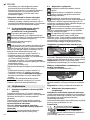
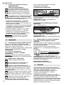
ENGLISH en
13
Original instructions
We, being solely responsible: Hereby declare that
these angle grinders, identified by type and serial
number *1), meet the requirements of all relevant
directives *2) and standards *3). Technical
documents for *4) - see page 3.
The angle grinders, when fitted with original Metabo
accessories, are suitable for grinding, sanding,
separating and wire brushing metal, concrete,
stone and similar materials without the use of water.
The user bears sole responsibility for any damage
caused by inappropriate use.
Generally accepted accident prevention
regulations and the enclosed safety information
must be observed.
For your own protection and for the
protection of your power tool, pay
attention to all parts of the text that are
marked with this symbol!
WARNING – Read the operating
instructions to reduce the risk of injury.
WARNING Read all safety warnings and
instructions. Failure to follow all safety
warnings and instructions may result in electric
shock, fire and/or serious injury.
Keep all safety instructions and information for
future reference.
Always include these documents when passing on
your power tool.
4.1 Safety Warnings Common for Grinding,
Sanding, Wire Brushing or Abrasive Cut-
ting-Off Operations:
Use
a) This power tool is intended to function as a
grinder, sander, wire brush or cut-off tool. Read
all
safety warnings,
instructions, illustrations
and specifications provided with this power
tool. Failure to follow all the instructions may result
in electric shock, fire and/or serious injury.
b) Operations such as polishing are not recom-
mended to be performed with this power tool.
Operations for which the power tool was not
designed may create a hazard and cause personal
injury.
c) Do not use accessories which are not specif-
ically designed and recommended by the tool
manufacturer. Just because the accessory can be
attached to your power tool, it does not assure safe
operation.
d) The rated speed of the accessory must be at
least equal to the maximum speed marked on
the power tool. Accessories running faster than
their rated speed can break and fly apart.
e) The outside diameter and the thickness of
your accessory must be within the capacity
rating of your power tool. Incorrectly sized acces-
sories cannot be adequately guarded or controlled.
f) Treaded mounting of accessories must
match the grinder spindle thread. For
accessories mounted by flanges, the arbour
hole of the accessory must fit the locating
diameter of the flange. Accessories that do not
match the mounting hardware of the power tool will
run out of balance, vibrate excessively and may
cause loss of control.
g) Do not use a damaged accessory. Before
each use, inspect accessories such as abra-
sive wheels for chips and cracks, backing pad
for cracks, tear or excess wear, wire brush for
loose or cracked wires. If a power tool or
accessory is dropped, check it for damage or
install an undamaged accessory. After
inspecting and installing an accessory, posi-
tion yourself and bystanders away from the
plane of the rotating accessory and run the
power tool at maximum no-load speed for one
minute. Damaged accessories will normally break
apart during this test time.
h) Wear personal protective equipment.
Depending on application, use a face shield,
safety goggles or safety glasses. As appro-
priate, wear dust mask, hearing protectors,
gloves and workshop apron capable of stop-
ping small abrasive or workpiece fragments.
The eye protection must be capable of stopping
flying debris generated by various operations. The
dust mask or respirator must be capable of filtering
particles generated by your operation. Prolonged
exposure to high intensity noise may cause hearing
loss.
i) Keep bystanders a safe distance away from
work area. Anyone entering the work area must
wear personal protective equipment. Fragments
of workpiece or of a broken accessory may fly away
and cause injury beyond immediate area of opera-
tion.
j) Hold the power tool by insulated gripping
surfaces only, when performing an operation
where the cutting accessory may contact
hidden wiring or its own cord. Cutting accessory
contacting a "live" wire may make exposed metal
parts of the power tool "live" and could give the
operator an electric shock.
k) Position the cord clear of the spinning acces-
sory. If you lose control, the cord may be cut or
snagged and your hand or arm may be pulled into
the spinning accessory.
1. Declaration of Conformity
2. Proper Use
3. General Safety Information
4. Special Safety Instructions

ENGLISHen
14
I) Never lay the power tool down until the
accessory has come to a complete stop. The
spinning accessory may grip the surface and pull
the power tool out of your control.
m) Do not run the power tool while carrying it at
your side. Accidental contact with the spinning
accessory could snag your clothing, pulling the
accessory into your body.
n) Regularly clean the power tool’s air vents.
The motor’s fan will draw the dust inside the housing
and excessive accumulation of powdered metal
may cause electrical hazards.
o) Do not operate the power tool near flam-
mable materials. Sparks could ignite these mate-
rials.
p) Do not use accessories that require liquid
coolants. Using water or other liquid coolants may
result in electrocution or shock.
4.2 Kickback and Related Warnings
Kickback is a sudden reaction to a pinched or
snagged rotating wheel, backing pad, brush or any
other accessory. Pinching or snagging causes rapid
stalling of the rotating accessory which in turn
causes the uncontrolled power tool to be forced in
the direction opposite to the accessory’s rotation at
the point of jamming.
For example, if an abrasive wheel is snagged or
pinched by the workpiece, the edge of the wheel
that is entering into the pinch point can dig into the
surface of the material causing the wheel to climb
out or kick out. The wheel may either jump toward or
away from the operator, depending on direction of
the wheel’s movement at the point of pinching.
Abrasive wheels may also break under these condi-
tions.
Kickback is the result of power tool misuse and/or
incorrect operating procedures or conditions and
can be avoided by taking proper precautions as
given below.
a) Maintain a firm grip on the power tool and
position your body and arm to allow you to
resist kickback forces. Always use the auxiliary
handle, if provided, for maximum control over
kickback or torque reaction during start-up.
The operator can control torque reactions or kick-
back forces, if proper precautions are taken.
b) Never place your hand near the rotating
accessory. Accessory may kickback over your
hand.
c) Do not position your body in the area
where power tool will move if kickback occurs.
Kickback will propel the tool in direction opposite to
the wheel’s movement at the point of snagging
d) Use special care when working around
corners, sharp edges etc. Avoid bouncing and
snagging the accessory. Corners, sharp edges or
bouncing have a tendency to snag the rotating
accessory and cause loss of control or kickback.
e) Do not attach a saw chain woodcarving
blade or toothed saw blade. Such blades create
frequent kickback and loss of control.
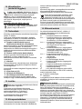
4.3 Safety Warnings Specific for Grinding
and Abrasive Cutting-Off Operations:
a) Use only wheel types that are recommended
for your power tool and the specific guard
designed for the selected wheel. Wheels for
which the power tool was not designed cannot be
adequately guarded and are unsafe.
b) The grinding surface of the centre depressed
wheels must be mounted below the plane of
the guard lip. An improperly mounted wheel that
projects through the plane of the guard lip cannot be
adequately protected.
c) The guard must be securely attached to the
power tool and positioned for maximum safety,
so the least amount of wheel is exposed
towards the operator. The guard helps to protect
the operator from broken fragments, accidental
contact with the wheel and sparks that could ignite
clothing.
d) Wheels must be used only for recommended
applications.
For example: do not grind with the side of the
cut-off wheel. Abrasive cut-off wheels are
intended for peripheral grinding, side forces applied
to these wheels may cause them to shatter.
e) Always use undamaged wheel flanges that
are of correct size and shape for your selected
wheel. Proper wheel flanges support the wheel
thus reducing the possibility of wheel breakage.
Flanges for cut-off wheels may be different from
grinding wheel flanges.
f) Do not use worn down wheels from larger
power tools. Wheels intended for larger power
tools are not suitable for the higher speed of a
smaller tool and may burst.
4.4 Additional Safety Warnings Specific for
Abrasive Cutting-Off Operations:
a) Do not “jam” the cut-off wheel or apply
excessive pressure. Do not attempt to make
excessively deep cuts. Overstressing the wheel
increases the loading and susceptibility to twisting
or binding of the wheel in the cut and the possibility
of kickback or wheel breakage.
b) Do not position your body in line with and
behind the rotating wheel. When the wheel, at the
point of operation, is moving away from your body,
the possible kickback may propel the spinning
wheel and the power tool directly at you.
c) If the wheel jams or if you interrupt a cut for
any reason, switch off the power tool and hold
the power tool motionless until the wheel
comes to a complete stop. Never attempt to
remove the cut-off wheel from the cut while the
wheel is in motion, otherwise kickback may
occur. Investigate and take corrective action to
eliminate the cause of the wheel jam.
d) Do not restart the cutting operation in the
workpiece. Let the wheel reach full speed and
carefully reenter the cut. The wheel may jam,
walk up or kickback if the power tool is restarted in
the workpiece.
e) Support panels or any oversized workpiece
to minimise the risk of wheel pinching and kick-

ENGLISH en
15
back. Large workpieces tend to sag under their own
weight. Supports must be placed under the work-
piece near the line of cut and near the edge of the
workpiece on both sides of the wheel.
f) Use extra caution when making a "pocket
cut" into existing walls or other blind areas. The
protruding wheel may cut gas or water pipes, elec-
trical wiring or objects that can cause kickback.
4.5 Safety Warnings Specific for Sanding
Operations:
a) Do not use oversized sanding disc paper.
Follow manufacturer's recommendations when
selecting sanding paper. Larger sanding paper
extending beyond the sanding pad presents a
laceration hazard and may cause snagging, tearing
of the disc or kickback.
4.6 Safety Warnings Specific for Wire Brush-
ing Operations:
a) Be aware that wire bristles are lost by the
brush even during ordinary operation. Do not
overstress the wires by applying excessive
load to the brush. The wire bristles can easily
penetrate light clothing and/or skin.
b) If the use of a safety guard is recommended
for wire brushing, do not allow any interference
of the wire wheel or brush with the guard. Wire
wheel or brush may expand in diameter due to work
load and centrifugal forces.
4.7 Additional Safety Instructions:
WARNING – Always wear protective
goggles.
Use elastic cushioning layers if they have been
supplied with the grinding media and if required.
Observe the specifications of the tool or accessory
manufacturer! Protect discs from grease or impact!
Grinding wheels must be stored and handled with
care in accordance with the manufacturer's
instructions.
Never use cut-off wheels for roughing work! Do not
apply pressure to the side of cut-off wheels.
The workpiece must lay flat and be secured against
slipping, e.g. using clamps. Large workpieces must
be sufficiently supported.
If accessories with threaded inserts are used, the
end of the spindle may not touch the base of the
hole on the sanding tool. Make sure that the thread
in the accessory is long enough to accommodate
the full length of the spindle. The thread in the
accessory must match the thread on the spindle.
See page 3 and the 14. Technical Specifications
chapter for more information on the spindle length
and thread.
It is recommended to use a stationary extraction
system and to place a ground fault circuit interrupter
(GFCI) downstream. If the angle grinder is shut
down via the GFCI, it must be checked and cleaned.
See the 9. Cleaning chapter for more information on
cleaning the motor.
Damaged, eccentric or vibrating tools must not be
used.
Avoid damage to gas or water pipes, electrical
cables and load-bearing walls (building structure).
Pull the plug out of the socket before making any
adjustments, converting or servicing the machine.
Metabo S-automatic safety clutch (WQ 1100-125,
WEQ 1400-125 only). When the safety clutch
activates, switch off the machine immediately!
A damaged or cracked additional handle must be
replaced. Never operate the machine with a
defective additional handle.
A damaged or cracked safety guard must be
replaced. Never operate a machine with a defective
safety guard.
This power tool is not suitable for polishing work.
Improper use of the machine will void the warranty!
The motor may overheat and damage the electric
power tool. We recommend using our angle
polisher for polishing work.
Secure small workpieces, for example by clamping
them in a vice.
Reducing dust exposure:
WARNING - Some dust created by power
sanding, sawing, grinding, drilling, and other
construction activities contains chemicals known to
cause cancer, birth defects or other reproductive
harm. Some examples of these chemicals are:
- Lead from lead-based paints,
- Crystalline silica from bricks and cement and
other masonry products, and
- Arsenic and chromium from chemically treated
lumber.
Your risk from these exposures varies, depending
on how often you do this type of work. To reduce
your exposure to these chemicals: work in a well
ventilated area, and work with approved safety
equipment, such as those dust masks that are
specially designed to filter out microscopic
particles.
This also applies to dust from other materials such
as some timber types (like oak or beech dust),
metals, asbestos. Other known diseases are e.g.
allergic reactions, respiratory diseases. Do not let
dust enter the body.
Observe the relevant guidelines and national
regulations for your material, staff, application and
place of application (e.g. occupational health and
safety regulations, disposal).
Collect the particles generated at the source, avoid
deposits in the surrounding area.
Use suitable accessories for special work. In this
way, fewer particles enter the environment in an
uncontrolled manner.
Use a suitable extraction unit.
Reduce dust exposure with the following measures:
- do not direct the escaping particles and the
exhaust air stream at yourself or nearby persons
or on dust deposits,
- use an extraction unit and/or air purifiers,

ENGLISHen
16
- ensure good ventilation of the workplace and keep
clean using a vacuum cleaner. Sweeping or
blowing stirs up dust.
- Vacuum or wash the protective clothing. Do not
blow, beat or brush.
See page 2.
1 M-Quick clamping nut*
2Support flange *
3Spindle
4 Spindle locking button
5 Sliding on/off switch *
6Handle
7 Speed adjustment wheel *
8Trigger*
9Switch-on lock*
10 Side handle
11 Safety cover
12 2-hole nut *
13 2-hole spanner *
14 Clamping nut (tool-free) *
15 Clip to tighten/release the (tool-free) clamping
nut manually *
16 Clamping screw*
17 Clamping ring*
18 Lever for safety guard attachment *
* depending on model / not in scope of delivery
Before commissioning, check that the rated
mains voltage and mains frequency stated on
the type plate match your power supply.
Always install an upstream GFCI with a
maximum trip current of 30 mA.
6.1 Attaching the additional handle
Always work with the additional handle (10)
attached! Attach the additional handle on the
left or right of the machine and secure.
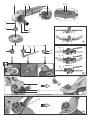
6.2 Attach the safety guard
For safety reasons, always use the safety
guard provided for the respective wheel! See
also chapter 11. Accessories!
Safety guard for grinding
Designed for work with roughing wheels, flap
sanding pads, diamond cutting discs.
W 850-100, W 850-115, W 850-125, WP 850-115,
WP 850-125, WEV 850-125, W 1100-115, W
1100-125 :
See illustration C on page 2.
- Loosen the clamping screw (16) until the clamping
ring (17) on the safety guard expands sufficiently.
- Place the safety guard (11) in the position
indicated.
- Turn the safety guard until the closed section is
facing the operator.
- Tighten the clamping screw (16) firmly. Make sure
that the guard is seated securely - you should not
be able to turn the safety guard (11).
WP 1100-115, WQ 1100-125, WEQ 1400-125:
See illustration D on page 2.
- Push and hold the lever (18). Place the safety
guard (11) in the position indicated.
- Release the lever and rotate the guard
until the lever latches.
- Push the lever and turn the safety guard until the
closed section is facing the operator.
- Make sure that the guard is attached securely:
The lever must engage and you should not be able
to turn the safety guard.
Use only accessories that
are covered by at least 3.4
mm by the safety guard.
Prior to any conversion work: pull the mains
plug out of the socket. The machine must be
switched off and the spindle at a standstill.
For reasons of safety, attach the cut-off
grinding guard before performing cut-off
grinding work (see Chapter 11. Accessories).
7.1 Locking the spindle
- Press in the spindle locking button (4) and
turn the spindle (3) by hand until the spindle
locking button engages.
7.2 Placing the grinding wheel in position
See illustration A on page 2.
- Fit the support flange (2) on the spindle. The
flange should not turn on the spindle when
properly attached.
Only W 850-100: Screw support flange with two-
hole spanner onto spindle so that the small collar
(with diameter 16 mm) is facing upwards.
- Place the grinding wheel on the support flange (2).
The grinding wheel must lay flat on the supporting
flange.
7.3 Securing/Releasing the "M-Quick"
clamping nut (depending on features)
Securing the "M-Quick" clamping nut (1):
Only for WQ1100-125; WEQ 1400-125.
Do not use the "M-Quick" clamping nut if the
accessory has a clamping shank thicker than
7,1 mm! In this case, use the 2-hole nut (12) with 2-
hole spanner (13).
- Lock the spindle (see chapter 7.1).
- Position the "M-Quick" clamping nut (1) on the
spindle (3) so that the 2 lugs engage in the 2
grooves on the spindle. See illustration on page 2.
- Tighten the "M-Quick"clamping nut by turning it
clockwise by hand.
5. Overview
6. Commissioning
7. Attaching the grinding wheel

ENGLISH en
17
- Turn the grinding wheel firmly clockwise to tighten
the "M-Quick"clamping nut.
Releasing the “M-Quick” clamping nut (1):
The "M-Quick” clamping nut (1) must be
attached before the spindle locking button (4)
can hold the spindle!
- The machine continues to run after switching off.
- Press in the spindle locking button (4) just before
the grinding wheel stops. The "M-Quick"clamping
nut (1) is released.
7.4 Securing/Releasing the 2-hole nut
(depending on features)
Securing the 2-hole nut (12):
The 2 sides of the two-hole nut are different.
Screw the two-hole nut onto the spindle as follows:
See illustration B on page 2.
- X) For thin grinding discs:
The edge of the 2-hole nut (12) faces upwards so
that the thin grinding disc can be attached
securely.
Y) For thick grinding discs:
The edge of the two-hole nut (12) faces
downwards so that the two-hole nut can be
attached securely to the spindle.
Z) Only for W 850-100:
The collar of the two-hole nut faces downwards
and/or the flat surface faces upwards.
- Lock the spindle. Turn the two-hole nut (12)
clockwise using the two-hole spanner (13) to
secure.
Releasing the 2-hole nut:
- Lock the spindle (see chapter 7.1). Turn the two-
hole nut (12) anticlockwise using the two-hole
spanner (13) to unscrew.
7.5 Securing/releasing the (tool-free)
clamping nut
(depending on features)
Only tighten the (tool-free) clamping nut (14)
by hand!
For the machine to operate, the clip (15) must
always lie flat on the clamping nut (1).
To secure the (tool-free) clamping nut (14):
Do not use the clamping nut (tool-free) if the
accessory has a clamping shank thicker than
6 mm! In this case, use the 2-hole nut (12) with 2-
hole spanner (13).
- Lock the spindle (see chapter 7.1).
- Flip up the clip (15) on the clamping nut.
- Fit the clamping nut (14) on the spindle (3). See
illustration on page 2.
-Tighten the clamping nut on the clip (15)
manually in a clockwise direction.
- Flip down the clip (15) again .
Release the (tool-free) clamping nut (14):
- Lock the spindle (see chapter 7.1).
- Flip up the clip (15) on the clamping nut.
- Unscrew the clamping nut (14), turning it
anticlockwise manually .
Note:
If the clamping nut is very tightly secured (14),
you can also use a two-hole spanner to unscrew it.
8.1 Setting the speed (WEV 850-125)
Set the recommended speed using the thumbwheel
(7). (Lower number = lower speed; higher number =
higher speed)
Cutting disc, roughing disc, cup wheel and diamond
cutting disc: high speed
Brush: medium speed
Sanding plate: low to medium speed
Note:
We recommend using our angle polisher for
polishing work.
8.2 Switching on and off
Always guide the machine with both hands.
Switch on first, then guide the accessory
towards the workpiece.
The machine must not be allowed to draw in
additional dust and shavings. When switching
the machine on and off and keep it away from dust
deposits. After switching off the machine, only set it
down when the motor has come to a standstill.
Avoid inadvertent starts: always switch the
tool off when the plug is removed from the
mains socket or if there has been a power cut.
In continuous operation, the machine
continues running if it is forced out of your
hands. Therefore, always hold the machine with
both hands using the handles provided, stand
securely and concentrate.
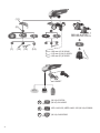
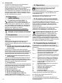
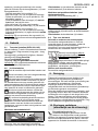
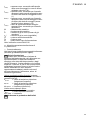
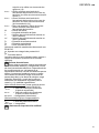
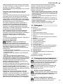
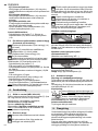
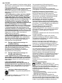
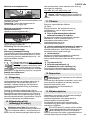
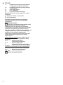
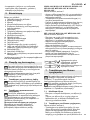
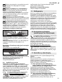
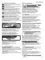
Machines with a slide switch:
Switching on: push the slide switch (5) forwards.
For continuous operation, tilt it downwards until it
engages.
Switching off: press the rear end of the slide switch
(5) and release it.
Machine with paddle switch (with deadman
function):
(Machines with the designation WP...)
Switching on: Slide the switch-on lock (9) in the
direction of the arrow and press the trigger (8).
Switching off: Release the trigger switch (8).
8. Use
0
I
5
0
I
88 989

ENGLISHen
18
8.3 Working Directions
Grinding and sanding operations:
Press down the machine evenly on the surface and
move it back and forth so that the surface of the
workpiece does not become too hot.
Rough grinding: position the machine at an angle of
30° - 40° for the best working results.
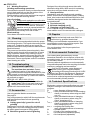
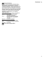
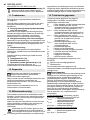
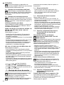
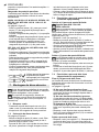
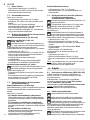
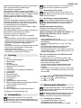
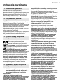
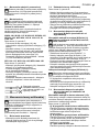
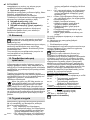
Cut-off grinding:
Always work against the run of the disc
(see illustration). Otherwise the
machine may kick back from the cut in
an out of control manner. Guide the
machine evenly at a speed suitable for
the material being processed. Do not tilt, apply
excessive force or sway from side to side.
Wire brushing:
Press down the machine evenly.
Particles may become deposited inside the power
tool during operation. This impairs the cooling of the
power tool. Conductive build-up can impair the
protective insulation of the power tool and create an
electrical hazard.
The power tool should be cleaned regularly, often
and thoroughly through all front and rear air vents
using a vacuum cleaner or by blowing in dry air.
Before doing so, separate the power tool from the
power source and wear protective goggles and a
dust mask. Ensure appropriate suction is available
when blowing out vents.
The machine does not start. Restart
protection is active. If the mains plug is
inserted with the machine switched on or if the
power supply is restored following an interruption,
the machine does not start up. Switch the machine
off and back on again.
WEV 850-125, WEQ 1400-125 only:
The speed drops while the machine is
under load. There is too much load on the
machine! Allow the machine to run at idle
speed until it has cooled down.
Use only genuine Metabo accessories.
See page 4.
Only use accessories which fulfil the requirements
and specifications listed in these operating
instructions.
A Cutting guard clip / guard for cut-off
grinding
Designed for work with cutting disc and diamond
cutting discs. Once the cutting guard clip is fitted,
the safety guard becomes a cutting guard.
B Extraction guard for cut-off grinding
Designed for cutting through stone slabs with
diamond cutting discs. With nozzle for extracting
stone dust using a suitable extraction unit.
C Hand protection
Intended for work with backing pads, sanding
plates, wire brushes and support plates, sanding
pads, wire brushes and diamond drill bits for tiles.
Install the hand guard under the additional side-
mounted handle.
D Two hole nut (12)
E M-Quick clamping nut (1)
F Clamping nut (tool-free) (14)
For a complete range of accessories, see
www.metabo.com or the accessories catalogue.
Repairs to electrical tools must ONLY be
carried out by qualified electricians!
Contact your local Metabo representative if you
have Metabo power tools requiring repairs. See
www.metabo.com for addresses.
You can download a list of spare parts from
www.metabo.com.
The sanding dust generated may contain
hazardous materials: do not dispose of dust with
household waste, but at a special collection point
for hazardous waste.
Observe national regulations on environmentally
compatible disposal and on the recycling of disused
machines, packaging and accessories.
Only for EU countries: never dispose of
power tools in your household waste!
According to European Directive 2012/19/EU
on Waste from Electric and Electronic Equipment
and implementation in national law, used power
tools must be collected separately and recycled in
an environmentally-friendly manner.
Explanatory notes on the specifications on page 3.
Subject to change in accordance with technical
progress.
Ø =max. diameter of the accessory
t
max,1
=max. permitted thickness of the clamping
shank on accessory when using two-hole
nut (12)
t
max,2
=max. permitted thickness of clamping
shank on accessory when using "M-
Quick" clamping nut (1)
t
max,3
=max. permitted thickness of clamping
shank on accessory when using (tool-
free) clamping nut (14)
t
max,4
=roughing disc/cutting disc:
max. permitted thickness of accessory
M=Spindle thread
l =Length of the sanding spindle
n* =No-load speed (maximum speed)
n
V
* =No-load speed (adjustable)
9. Cleaning
10. Troubleshooting
(equipment-specific)
11. Accessories
12. Repairs
13. Environmental Protection
14. Technical Specifications

ENGLISH en
19
P
1
=Rated input power
P
2
=Power output
m =Weight without mains cable
Measured values determined in conformity with
EN 60745.
Machine in protection class II
~ AC power
The technical specifications quoted are subject to
tolerances (in compliance with relevant valid
standards).
Emission values
These values make it possible to assess the
emissions from the power tool and to compare
different power tools. The actual load may be higher
or lower depending on operating conditions, the
condition of the power tool or the accessories used.
Please allow for breaks and periods when the load
is lower for assessment purposes. Arrange
protective measures for the user, such as
organisational measures based on the adjusted
estimates.
Total vibration value
(vector sum of three directions)
determined in accordance with EN 60745:
a
h, SG
= Vibration emission value
(surface grinding)
a
h, DS
= Vibration emission value
(sanding with sanding plate)
K
h,SG/DS
= Uncertainty (vibration)
Typical A-effective perceived sound levels
:
L
pa
= Sound-pressure level
L
WA
=Acoustic power level
K
pA
, K
WA
= Uncertainty
Wear ear protectors!
Page is loading ...
Page is loading ...
Page is loading ...
Page is loading ...
Page is loading ...
Page is loading ...
Page is loading ...
Page is loading ...
Page is loading ...
Page is loading ...
Page is loading ...
Page is loading ...
Page is loading ...
Page is loading ...
Page is loading ...
Page is loading ...
Page is loading ...
Page is loading ...
Page is loading ...
Page is loading ...
Page is loading ...
Page is loading ...
Page is loading ...
Page is loading ...
Page is loading ...
Page is loading ...
Page is loading ...
Page is loading ...
Page is loading ...
Page is loading ...
Page is loading ...
Page is loading ...
Page is loading ...
Page is loading ...
Page is loading ...
Page is loading ...
Page is loading ...
Page is loading ...
Page is loading ...
Page is loading ...
Page is loading ...
Page is loading ...
Page is loading ...
Page is loading ...
Page is loading ...
Page is loading ...
Page is loading ...
Page is loading ...
Page is loading ...
Page is loading ...
Page is loading ...
Page is loading ...
Page is loading ...
Page is loading ...
Page is loading ...
Page is loading ...
Page is loading ...
Page is loading ...
Page is loading ...
Page is loading ...
Page is loading ...
Page is loading ...
Page is loading ...
Page is loading ...
Page is loading ...
Page is loading ...
Page is loading ...
Page is loading ...
Page is loading ...
Page is loading ...
Page is loading ...
Page is loading ...
Page is loading ...
Page is loading ...
Page is loading ...
Page is loading ...
Page is loading ...
Page is loading ...
Page is loading ...
Page is loading ...
Page is loading ...
Page is loading ...
Page is loading ...
Page is loading ...
Page is loading ...
Page is loading ...
Page is loading ...
Page is loading ...
Page is loading ...
Page is loading ...
Page is loading ...
Page is loading ...
Page is loading ...
Page is loading ...
Page is loading ...
Page is loading ...
Page is loading ...
Page is loading ...
Page is loading ...
Page is loading ...

Metabowerke GmbH
Metabo-Allee 1
72622 Nuertingen
Germany
www.metabo.com
170 27 5850 - 0219
-
 1
1
-
 2
2
-
 3
3
-
 4
4
-
 5
5
-
 6
6
-
 7
7
-
 8
8
-
 9
9
-
 10
10
-
 11
11
-
 12
12
-
 13
13
-
 14
14
-
 15
15
-
 16
16
-
 17
17
-
 18
18
-
 19
19
-
 20
20
-
 21
21
-
 22
22
-
 23
23
-
 24
24
-
 25
25
-
 26
26
-
 27
27
-
 28
28
-
 29
29
-
 30
30
-
 31
31
-
 32
32
-
 33
33
-
 34
34
-
 35
35
-
 36
36
-
 37
37
-
 38
38
-
 39
39
-
 40
40
-
 41
41
-
 42
42
-
 43
43
-
 44
44
-
 45
45
-
 46
46
-
 47
47
-
 48
48
-
 49
49
-
 50
50
-
 51
51
-
 52
52
-
 53
53
-
 54
54
-
 55
55
-
 56
56
-
 57
57
-
 58
58
-
 59
59
-
 60
60
-
 61
61
-
 62
62
-
 63
63
-
 64
64
-
 65
65
-
 66
66
-
 67
67
-
 68
68
-
 69
69
-
 70
70
-
 71
71
-
 72
72
-
 73
73
-
 74
74
-
 75
75
-
 76
76
-
 77
77
-
 78
78
-
 79
79
-
 80
80
-
 81
81
-
 82
82
-
 83
83
-
 84
84
-
 85
85
-
 86
86
-
 87
87
-
 88
88
-
 89
89
-
 90
90
-
 91
91
-
 92
92
-
 93
93
-
 94
94
-
 95
95
-
 96
96
-
 97
97
-
 98
98
-
 99
99
-
 100
100
-
 101
101
-
 102
102
-
 103
103
-
 104
104
-
 105
105
-
 106
106
-
 107
107
-
 108
108
-
 109
109
-
 110
110
-
 111
111
-
 112
112
-
 113
113
-
 114
114
-
 115
115
-
 116
116
-
 117
117
-
 118
118
-
 119
119
-
 120
120


Metabo WEQ 1400-125 User manual
- Category
- Angle grinders
- Type
- User manual
Ask a question and I''ll find the answer in the document
Finding information in a document is now easier with AI
in other languages
- italiano: Metabo WEQ 1400-125 Manuale utente
- français: Metabo WEQ 1400-125 Manuel utilisateur
- español: Metabo WEQ 1400-125 Manual de usuario
- Deutsch: Metabo WEQ 1400-125 Benutzerhandbuch
- русский: Metabo WEQ 1400-125 Руководство пользователя
- Nederlands: Metabo WEQ 1400-125 Handleiding
- português: Metabo WEQ 1400-125 Manual do usuário
- dansk: Metabo WEQ 1400-125 Brugermanual
- polski: Metabo WEQ 1400-125 Instrukcja obsługi
- svenska: Metabo WEQ 1400-125 Användarmanual
- suomi: Metabo WEQ 1400-125 Ohjekirja
Related papers
-
Metabo W 17-150 Operating instructions
-
Metabo WX 2400-230 Operating instructions
-
Metabo W 780 Owner's manual
-
Metabo WQ 10-125 Plus Operating instructions
-
Metabo WP 2200-180 Operating instructions
-
Metabo WX 24-230 Operating instructions
-
Metabo W 780 Operating instructions
-
Metabo WX 21-180 Operating instructions
-
Metabo W 14-125 Ergo Operating instructions
-
Other documents
-
Skil 9781MA User manual
-
Skil 9345 AG User manual
-
Flex L 26-6 230 User manual
-
Flex L 14-11 125 Owner's manual
-
Bosch GWS 7-115 Specification
-
Parkside PWS 125 C3 Original Instructions Manual
-
-
-
Parkside PWS 125 A1 User manual
-
Parkside PWS 125 F5 Translation Of The Original Instructions