Bosch DWA061450/02 Owner's manual
- Category
- Baby night-lights
- Type
- Owner's manual

Montageanleitung
Installation Instructions
Notice de montage
Montagevoorschriften
Instrucciones de montaje
Instruções de montagem
Monteringsanvisning
Monteringsanvisning
Asennusohje
Montagevejledning
Instrukcja montażu
Montaj kilavuzu
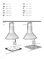
DE
EN
FR
PT
ES
NL
DA
SV
NO
FI
PL
TR
Page is loading ...
Page is loading ...
Page is loading ...
Page is loading ...
Page is loading ...
Page is loading ...
Page is loading ...

9
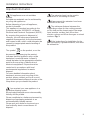
Installation Instructions:
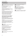
Important information
Old appliances are not worthless
rubbish.
Valuable raw materials can be reclaimed by
recycling old appliances.
Before disposing of your old appliance,
render it unusable.
This appliance is marked according to the
European directive 2002/96/EC on Waste
Electrical and Electronic Equipment (WEEE).
By ensuring this product is disposed of
correctly, you will help prevent potential
negative consequences for the environment
and human health, which could otherwise be
caused by inappropriate waste handling of
this product.
The symbol on the product, or on the
documents accompanying the product,
indicates that this appliance may not be
treated as household waste. Instead it
should be taken to the appropriate collection
point for the recycling of electrical and
electronic equipment. Disposal must be
carried out in accordance with local
environmental regulations for waste
disposal.
For more detailed information about
treatment, recovery and recycling of this
product, please contact your local council,
your household waste disposal service or the
shop where you purchased the product.
You received your new appliance in a
protective shipping carton.
All packaging materials are environmentally
friendly and recyclable.
Please contribute to a better environment by
disposing of packaging materials in an
environmentally-friendly manner.
Please ask your dealer or inquire at your
local authority about current means of
disposal.
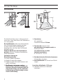
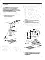
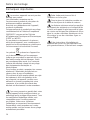
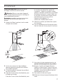
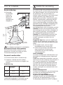
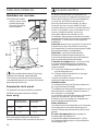
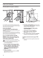
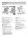
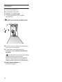
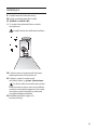
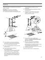
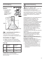
The extractor hood can be used in
exhaust air or circulating air mode.
Always mount the extractor hood over
the centre of the hob.
The minimum distance between the
supporting surface for the cooking vessels
on the hob and the lowest part of the range
hood must be not less than 60cm from
electric cookers and 65cm from gas or mixed
cookers. Fig. 1
If the instructions for installation for the
gas hob specify a greater distance, this must
be adhered to.

10
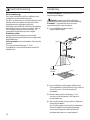
120
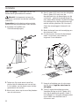
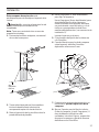
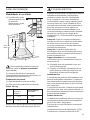
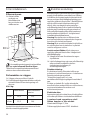
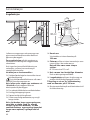
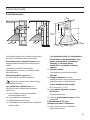
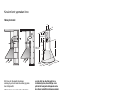
Prior to installation
❑ Round pipes:
We recommend Internal diameter:
120 mm
❑ Flat ducts must have an internal cross
section that equates to that of round
pipes.
There should be no sharp bends.
Ø 120 mm approx. 113 cm
2
.
❑ If pipes have different diameters:
Insert sealing strip.
❑ For exhaust-air mode, ensure that there
is an adequate supply of fresh air.
Connecting a Ø 120 mm exhaust-air pipe:
❑ Mount the pipe directly onto the air outlet
on the hood.
The exhaust air is discharged upwards
through a ventilation shaft or directly through
the outside wall into the open.
For operating in exhaust-air mode, a one-
way flap should be mounted inside the wall
ventilation box.
If no one-way flap was enclosed with the
hood, it can be obtained from a specialist
retailer.
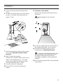
Installing the one-way flap:
❑ Snap the one-way flap into the air pipe.
The two lightly sprung flaps must be
able to move upwards.
If the exhaust air is going to be
discharged into the open, a telescopic wall
box should be fitted into the outside wall.
❑ For optimum extractor hood efficiency:
❑ Short, smooth air exhaust pipe.
❑ As few bends in the pipe as possible.
❑ Diameter of pipe to be as large as
possible and no tight bends in pipe.
If long, rough exhaust-air pipes, many
pipe bends or smaller pipe diameters
are used, the air extraction rate will no
longer be at an optimum level and
there will be an increase in noise.
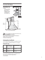
120
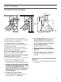
Exhaust-air mode
175
158
30
396
419
375
11
MAX. 1171
MIND. 887
598 - (898)
490
(522)
MIND. 95
MAX. 375
490

11
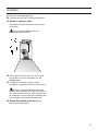
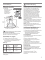
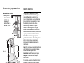
Circulating-air mode
❑ With activated
carbon filter if
exhaust-air mode
is not possible.
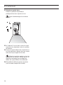
Electrical connection
Risk of electric shock!
The appliance features an EU safety plug. To
ensure protective earthing in a Danish
socket, the appliance must be connected to a
suitable plug adapter. This adapter
(permitted up to max. 13 amps) is available
from customer service (spare part no.
616581).
The mains power supply must correspond to
the rating indicated on the plate situated
inside the hood. If provided with a plug
connect the hood to a socket in compliance
with current regulations and positioned in an
accessible area. If it not fitted with a plug
(direct mains connection) or if the plug is not
located in an accessible area apply a bi-
polar switch in accordance with standards
which assures the complete disconnection of
the mains under conditions relating to over-
current category III, in accordance with
installation instructions.
Warning! Before re-connecting the hood
circuit to the mains supply and checking the
efficient function, always check that the
mains cable is correctly assembled.
Warning! Power cable replacement must be
undertaken by the authorized service
assistance centre or similar qualified person.
Connect the hood to a norm complying plug
only. The plug should be located in an
accessible zone.
❑ The plug must be equipped with a
protection circuit.
❑ If after installation the plug can not be
reached, a disconnecting device must be
envisaged.
Circulating-air
mode
60 cm
90 cm
Exhaust-air
mode
10,3
13,2
11,5
14,4
30
396
419
375
MAX. 1171
MIND. 887
598 - (898)
490
(522)
MIND. 95
MAX. 375
490
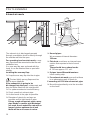
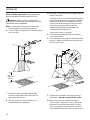
Prior to installation
The complete installation set can be
obtained from specialist outlets.
The corresponding accessory numbers can
be found at the end of these operating
instructions.
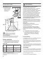
Preparing the wall
❑ The wall must be flat and perpendicular.
❑ Ensure that the wall is capable of
providing a firm hold for mounting screws
and plugs.
Weight in kg:
We reserve the right to construction changes
within the context of technical development.

12
Fixed installation:
The fixed installation can be carried out by a
qualified and authorized person only.
Envisage an omnipolar switch having a
contact opening of at least 3mm, including an
automatic circuit breaker.
The cable must be replaced by the
manufacturer, the assistance centre or a
qualified and authorized person only, in
order to avoid any dangers.
Electrical data:
The technical data of the device are on the
distinctive label inside the device behind the
grease filters.
In case of repair, disconnect the electric
supply from the cooker hood.
Length of the feeding cable: 1,30m.
The hood complies with the EMC directives.
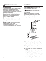
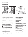
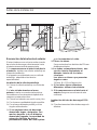
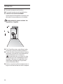
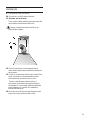
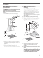
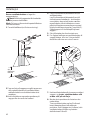
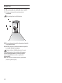
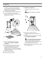
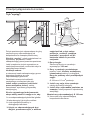
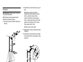
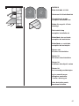
Installation
This extractor hood is intended to be
mounted onto the kitchen wall.
WARNING! Do not connect the
appliance to the mains until the installation is
fully complete.
Note: Take into account any special
accessories that are going to be fitted.
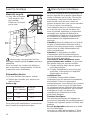
1. Remove the grease filter (refer to
Operating Instructions).
min.
600 Elektro
650 Gas
2. Draw a line on the wall from the ceiling to
the lower edge of the hood at the centre
of the location where the hood is going to
be mounted.
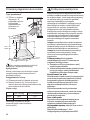
3. Using the template, mark positions on the
wall for the screws.
4. Drill 2 holes (dia. 8 mm) for the extractor
hood.
Drill 2 holes (dia. 8 mm) for the bracket for
fixing the flue ducts - use the bracket as a
template: this should be fit close to the
ceiling so that index printed on the bracket
matches with the line previously marked
(see step 2).
Insert wall plugs flush with the wall.
Electrical connection

13
5. Screw on the bracket for fixing the flue
ducts.
6. In order to help fix the hood onto the wall,
screw in 2 screws until it protrudes by
approx. 5 mm.
7. Hook the extractor hood over the screws
in the wall, align the extractor hood
properly.
8. Mark 2 lower fixing points.
Remove the hood and drill 2 holes (dia. 8
mm) on the marked points. Fit 2 wall
plugs, Hang again the hood and fix the
hood permanently with 2 screws.
9. Connect up the air outlet pipe.
10. Connect the hood to the electricity
supply.
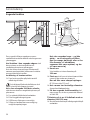
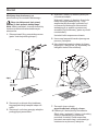
Installation
11. Stainless steel model:
Remove the protective film from the two
flue ducts.
Avoid damage to the sensitive
surface.
12. Screw the upper flue duct to the sides of
the fixing bracket with 2 short screws.
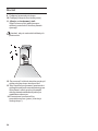
13. Position the lower flue duct on the
extractor hood, align the flue duct.
To prevent scratching the upper duct
when pushing on the lower duct, cover
the edge of the lower duct with the
installation template or other protective
material.
14. Re-insert the grease filter (see operating
instructions).
Page is loading ...
Page is loading ...
Page is loading ...
Page is loading ...
Page is loading ...
Page is loading ...
Page is loading ...
Page is loading ...
Page is loading ...
Page is loading ...
Page is loading ...
Page is loading ...
Page is loading ...
Page is loading ...
Page is loading ...
Page is loading ...
Page is loading ...
Page is loading ...
Page is loading ...
Page is loading ...
Page is loading ...
Page is loading ...
Page is loading ...
Page is loading ...
Page is loading ...
Page is loading ...
Page is loading ...
Page is loading ...
Page is loading ...
Page is loading ...
Page is loading ...
Page is loading ...
Page is loading ...
Page is loading ...
Page is loading ...
Page is loading ...
Page is loading ...
Page is loading ...
Page is loading ...
Page is loading ...
Page is loading ...
Page is loading ...
Page is loading ...
Page is loading ...
Page is loading ...
Page is loading ...
Page is loading ...
Page is loading ...
Page is loading ...
Page is loading ...
Page is loading ...
Page is loading ...
Page is loading ...

67
DHZ5215
EAN 4242 002 411 231
Starterset für Umluftbetrieb
Circulating-air mode -
complete installation set
Mode Air recyclé - Kit de
montage
Recirculatie kap
complete installatie set
Modalidad aire reciclada,
completo de instalacion
Modalidade ar reciclado,
completo de instalação.
Starter sæt
til intern recirkulation
Starter kit
För intern återcirkulation
Starter kit
sisäilman kierrätystä varten
Starter kit
for innvendig resirkulasjon
tryb z wewnêtrznym
obiegiem powietrza,
³¹cznie z monta¿em
Hava devir daim modu,
kurulumu ile birlikte
Page is loading ...
-
 1
1
-
 2
2
-
 3
3
-
 4
4
-
 5
5
-
 6
6
-
 7
7
-
 8
8
-
 9
9
-
 10
10
-
 11
11
-
 12
12
-
 13
13
-
 14
14
-
 15
15
-
 16
16
-
 17
17
-
 18
18
-
 19
19
-
 20
20
-
 21
21
-
 22
22
-
 23
23
-
 24
24
-
 25
25
-
 26
26
-
 27
27
-
 28
28
-
 29
29
-
 30
30
-
 31
31
-
 32
32
-
 33
33
-
 34
34
-
 35
35
-
 36
36
-
 37
37
-
 38
38
-
 39
39
-
 40
40
-
 41
41
-
 42
42
-
 43
43
-
 44
44
-
 45
45
-
 46
46
-
 47
47
-
 48
48
-
 49
49
-
 50
50
-
 51
51
-
 52
52
-
 53
53
-
 54
54
-
 55
55
-
 56
56
-
 57
57
-
 58
58
-
 59
59
-
 60
60
-
 61
61
-
 62
62
-
 63
63
-
 64
64
-
 65
65
-
 66
66
-
 67
67
-
 68
68


Bosch DWA061450/02 Owner's manual
- Category
- Baby night-lights
- Type
- Owner's manual
Ask a question and I''ll find the answer in the document
Finding information in a document is now easier with AI
in other languages
- français: Bosch DWA061450/02 Le manuel du propriétaire
- español: Bosch DWA061450/02 El manual del propietario
- Deutsch: Bosch DWA061450/02 Bedienungsanleitung
- Nederlands: Bosch DWA061450/02 de handleiding
- português: Bosch DWA061450/02 Manual do proprietário
- dansk: Bosch DWA061450/02 Brugervejledning
- polski: Bosch DWA061450/02 Instrukcja obsługi
- Türkçe: Bosch DWA061450/02 El kitabı
- svenska: Bosch DWA061450/02 Bruksanvisning
- suomi: Bosch DWA061450/02 Omistajan opas
Related papers
-
Bosch DKE745K/01 Operating instructions
-
Bosch DWA092550/01 Owner's manual
-
Bosch DKE 635 G Owner's manual
-
Bosch DWB 092750 Owner's manual
-
-
-
-
-
Bosch DKE735F/01 Owner's manual
-
Bosch DHZ1226 Owner's manual
Other documents
-
Siemens iQ300 LU29250 Owner's manual
-
Whirlpool AKR 749/1 IX Owner's manual
-
Siemens LC654DA10/01 User manual
-
-
BALAY 3BD791XP/01 User manual
-
-
-
-
Siemens LC756GA40/01 Owner's manual
-