Page is loading ...

Bienvenue dans le monde de Boston!
ENGLISH
FRANÇAIS
Description
Thank you for purchasing these new Voyager
®
speakers. Combining the famous Boston sound
with the latest and best weather resistance and manufacturing methods, the Voyagers are ideally
suited to anything you can throw at them. Try outdoor use – sun, rain, snow, heat, and cold – or
marine use. They are equally at home in your home, for background music, hi-fi, or home theater.
All models in the Voyager line are true two-way designs with all acoustic parts sealed and
gasketed against penetrating weather.
Drawing from over a decade of all-weather speaker expertise, Boston built the Voyager series to
minimize exposure of acoustic parts to weather and with materials proven to resist the elements:
polypropylene cabinets with UV light and impact resistance, all-aluminum grilles and brackets,
gold-plated speaker connectors. All drivers are manufactured from high-tech plastics, rubbers,
and other materials that have been extensively tested for durability. Versatile brackets simplify
installation in many situations (and the speakers’ shape makes corner placement easy). The
large, grippy knobs make adjustment to speaker angle easy.
Basic Hookup
1. Connect the speaker
terminals to the amplifier
speaker outputs.
2. When making all
connections, be sure to connect
+ to + (red) and – to – (black).
Note: The Voyager
®
Metro
requires connection of both left
and right speaker wires to the
one speaker.
Checking the Speaker Connections
It is important that your speakers are hooked up with similar polarity or “in phase.” A simple
listening test will tell you if your speakers are connected properly. Place the speakers face to face,
as closely together as possible. While listening to music with your amplifier set to MONO, reverse
the connections at one speaker only. You’ll hear a dramatic change in sound. The connection that
yields the fuller bass and louder sound is correct.
Listening Levels and Power Handling
The listed power recommendations assume you will operate your system in a way that will not
produce distortion. Even these rugged speakers can be damaged by a modest amplifier if it
produces distortion. If you
hear a harsh, gritty noise, turn down the volume. Prolonged or repeated
operation of your speaker with a distorted signal from the amplifier can cause damage that is not
covered by the warranty.
How to Place Your Speakers
Placement is one of the most important factors for sound quality. Taking a few minutes to place
your speakers correctly ensures that your speakers will sound best in any indoor or outdoor
environment. For best stereo effect, separate the speakers by at least 3-6 ft. (1-2m). Typically,
placement near a wall or other surface will increase the bass output of the speaker. Corner
placement will give still more bass. Outdoors, placement under the eaves of a roof reduces
exposure to constant direct sunlight and precipitation, which will extend the speaker’s life.
Placement under the eaves or on a wall near the ground will increase bass. In situations where you
need to avoid disturbing neighbors, you may wish to install the speakers on a post or railing facing
the house and listening area (the sound area will be more contained).
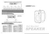
Mounting the speakers
Before running permanent wires and mounting the
speaker, you may wish to test the speaker
placement first for coverage and good stereo
sound.
Use the supplied bracket to mount the speaker
vertically or horizontally on walls or other surfaces.
The bracket includes keyhole sockets and other
holes to suit a variety of hardware. Consult a
knowledgeable person about the best hardware to
use for your particular wall surface.
For mounting, remove the bracket from the speaker.
If running wires, you may wish to route the wiring
through the bracket’s large middle hole; the
bracket will cover the hole in the wall. Mount the
bracket and attach the speaker. Adjust the speaker
to face the listening area.
Alternatively, you may use mounting brackets
made by other companies. The 1 ⁄4–20 threaded
inserts for the knob match various brackets and
mounting plates. The Voyager
®
7 includes two
more inserts on the rear of the cabinet. Consult
your dealer or the bracket manufacturer for more
information.
Public address installations
The Voyager models include internal screw holes for 70V matching transformers used in
professional PA installations. These holes are designed for transformers with two mounting points
spaced 2-3" (52-76mm) apart (Voyager 4,5, and 7) and for a transformer adaptor plate with four
holes (Voyager 6 and Metro). Use self-tapping #6 x 3/8" screws (metric equivalent: M3.5 x 10mm).
To mount a transformer, remove the speaker grille (see above), and then remove the recessed
screws holding the front baffle. Connect the transformer wires with wire nuts or solder. Test the
speaker and reattach the front baffle, making sure the sealing gasket is in place. Do not over-
tighten the recessed screws, or the plastic screw threads will strip.
Maintenance
Voyager speakers require no more than occasional dusting or wiping with a soft cloth. When the
speakers are installed in hard-to-reach locations, you may brush them with a soft broom. Avoid
directing a garden hose at the speaker—it can damage the drivers or dislodge the wiring.
If Service Seems Necessary
First, contact the dealer from whom you purchased the speakers. If that is not possible, write to:
Boston Acoustics, Inc. 300 Jubilee Drive Peabody, MA 01960 U.S.A.
We will promptly advise you of what action to take.
IMPORTANT: Typically, one side of the wire
is smooth. Connect this side to the – (black)
connection. The other side has a rib or
stripe or other marking. Connect this to the
+ (red) connection.
Using the five-way binding posts: The binding
posts permit easy connection to banana
plugs, spade lugs, and bare wire. Insert the
wire in the hole and tighten.
Enjoy your New Voyager speakers!
amplifier or receiver
How to Connect Your Speakers
You need to wire your speakers correctly to obtain the best sound quality and a proper stereo
image. Wiring should take a few minutes, but it’s important to do it carefully, since incorrect wiring
(such as reversed connections) can result in a poor stereo soundstage or poor bass. We
recommend 18 gauge (or heavier) lamp cord or speaker wire for runs of up to 25 feet (8m), and
thicker 16 gauge for longer runs. Strip 1 /2" (12mm) of insulation off the ends of each speaker cable
to expose the two conductors, and tightly twist the wire strands. In installations where wiring is run
on or through a building, use appropriate weatherproof wire that complies with local codes. See
your dealer or other knowledgeable person for recommendations on suitable wiring.
WARNING:
To prevent electrical shock hazard, always switch off the amplifier or receiver when making
connections to the speaker. When making all connections, be sure to connect the + (red) on the
speaker to the + (red) on the amplifier, and the - (black) on the speaker to the – (black) on the
amplifier.
Mounting Options Voyager
®
7 All other models
Insert Size 1/4–20 1/4–20
Insert Location Top, Bottom, Top and Bottom
and 2 on rear, 3" (76.2mm) apart
Voyager
®
7 mounting inserts
Frequency Response
(±3dB)
Recommended Amplifier
Power
Nominal Impedance
Sensitivity
[1 watt (2.83v) at 1m]
Bass Unit
copolymer cone with butyl
rubber surround
Tweeter
Crossover Frequency
Dimensions
without bracket (HxWxD)
Grille & Bracket
corrosion resistant
Housing
V
OYAGER
®
7
S
PECIFICATIONS
59Hz-20kHz
15-150 watts
8 ohms
90dB
7” (180mm)
1"
(25 mm)
Kortec
®
2500 Hz
14
1
/
2
x 9
7
/
8
x
8
3
/
4
Inches
368x251x212
mm
powder-coated
aluminum
polypropylene
80Hz-20kHz
15-100 watts
8 ohms
89dB
4
1
/
2
” (115mm)
3/4
" (19mm)
Kortec
®
3500 Hz
9
3
/
4
x
6
7
/
8
x
5
7
/
8
Inches
238x175x149
mm
powder-coated
aluminum
polypropylene
65Hz-20kHz
15-100 watts
(Per channel)
8 ohms x 2
(Per channel)
89dB
6
1
/
2
” (165mm)
(2) 1
"
(25mm)
Kortec
®
2500 Hz
9 x
13 x
7
3
/
4
Inches
229x330x197
mm
powder-coated
aluminum
polypropylene
65Hz-20kHz
15-125 watts
8 ohms
89dB
6
1
/
2
” (165mm)
1
" (25 mm)
Kortec
®
2500 Hz
13
x 9 x 7
3
/
4
Inches
330x229x197
mm
powder-coated
aluminum
polypropylene
70Hz-20kHz
15-100 watts
8 ohms
89dB
5
1
/
4
” (135mm)
3/4
" (19mm)
Kortec
®
3500 Hz
11
1
/
4
x
8
1
/
4
x 7
Inches
286x210x177
mm
powder-coated
aluminum
polypropylene
V
OYAGER
®
6
V
OYAGER
®
5
V
OYAGER
®
4
V
OYAGER
®
M
ETRO
Description
Nous vous remercions d’avoir acheté ces nouveaux haut-parleurs Voyager
®
. L’association de la
tradition Boston aux toutes dernières méthodes de fabrication, et leur résistance à toutes les
conditions météorologiques offrent des Voyagers parfaitement adaptés à toute utilisation. Que
ce soit en extérieur – sous le soleil, la pluie, la chaleur et le froid –, sur votre bateau, ou tout
simplement chez vous, leur qualité excellente est sans équivalent, et ceci aussi bien en musique
de fond, associé à du matériel haute fidélité, ou dans une installation home cinema. Tous les
modèles de la gamme Voyager ont une véritable conception à double sens, toutes les pièces
acoustiques étant scellées et rendues étanches contre les intempéries.
Avec plus de dix ans d’expérience dans le domaine des haut-parleurs tous temps, Boston a
conçu la série Voyager afin de réduire l’exposition des pièces acoustiques aux intempéries ,
pour résister aux éléments, en utilisant des matériaux adaptés:caissons en polypropylène
résistant aux rayons UV et aux chocs, grilles et support entièrement en aluminium, connecteurs
des haut-parleurs plaqué-or. Tous les transducteurs sont fabriqués à partir de plastiques,
caoutchoucs high-tech et autres matériaux dont la durabilité a été testée de manière intensive.
Des supports amovibles facilitent l’installation dans de nombreux emplacements (et la forme des
haut-parleurs leur permet d’être facilement installés dans un angle). Les grandes poignées,
facilement préhensibles, facilitent l’ajustement de l’orientation du haut-parleur.
Branchement de base
1. Branchez les terminaux du
haut-parleur aux sorties haut-
parleur de l’amplificateur.
2. Lorsque vous procédez à
tous les branchements, assurez-
vous de connecter le + (rouge)
au + (rouge) et le – (noir) au –
(noir) de l’amplificateur ou du
récepteur
Note : Le Voyager
®
Metro exige
le raccordement des deux fils
gauches et droits de haut-
parleur à l'un haut-parleur.
Installations de sonorisation
Les modèles Voyager comprennent des trous de fixation correspondant aux transformateurs 70 V
utilisés dans les installations de sonorisation professionnelles. Ces trous sont prévus pour des
transformateurs à deux points de fixation séparés de 52 à 76 mm (Voyager 4, 5 et 7) et pour une
platine adaptatrice de transformateur à quatre trous (Voyager 6 et Metro). Utilisez les vis M3.5 x
10mm. Pour monter un transformateur, ôtez la grille du haut-parleur (voir ci-dessus) puis ôtez les
vis à tête à empreinte maintenant le baffle frontal. Connectez les câbles du transformateur avec des
serre-fils ou points de soudure. Testez le haut-parleur et fixez de nouveau le baffle frontal, en vous
assurant que le joint d’étanchéité est en place. Ne serrez pas trop les vis à tête à empreinte, car le
fileté en plastique des vis risque de se détériorer.
Entretien
Les haut-parleurs Voyager ne nécessitent pas plus qu’un simple dépoussiérage ou nettoyage
occasionnel avec un chiffon doux. Lorsque les haut-parleurs sont installés dans des endroits
difficiles à atteindre, vous pouvez les brosser avec un balai doux. Evitez d’orienter un tuyau
d’arrosage vers les haut-parleurs – cela peut endommager les transducteurs ou déplacer les câbles.
Pour tout autre service
Contactez d’abord le revendeur chez qui vous avez achetez les haut-parleurs. Si cela est
impossible, écrivez à :
Boston Acoustics, Inc. 300 Jubilee Drive Peabody, MA 01960 U.S.A.
Nous vous indiquerons rapidement les mesures à prendre.
IMPORTANT : Généralement, un côté du
câble est lisse. Branchez ce côté à
l’extrémité – (noir). L’autre côté présente un
sillon ou une bande ou autre marque.
Branchez cette extrémité à la connexion +
(rouge).
Utilisation de bornes de connexion à cinq
points : Les bornes de connexion
permettent un raccordement facile aux
fiches bananes et fils dénudés. Insérez le fil
dans le trou et serrez.
amplificateur
Branchement de vos haut-parleurs
Vous devez brancher correctement vos haut-parleurs afin d’obtenir la meilleure qualité de son et
une parfaite image stéréo. Le branchement va prendre quelques minutes, mais il est important de
le faire soigneusement, car un mauvais branchement (à l’envers, par exemple) peut entraîner une
mauvaise qualité de son ou des basses étriquées.
Nous vous recommandons un câble électrique de calibre 18 (ou plus) ou un câble pour haut-
parleur d’une longueur maximale de 8 mètres. Otez la bande d’isolation sur 12 mm à chaque
extrémité du câble haut-parleur afin de dégager les deux conducteurs, et vissez à fond les torons
métalliques. Sur des installations où le câblage court le long ou à travers un bâtiment, utilisez les
câbles waterproof adéquats conformes aux normes locales. Pour de plus amples informations sur
les branchements, contactez votre revendeur local ou autre personne compétente.
ATTENTION :
Pour éviter tous risques de décharge électrique, éteignez toujours l’amplificateur
ou le récepteur lorsque vous procédez au branchement au haut-parleur.
Lorsque vous effectuez tous les branchements, assurez-vous de connecter le + (rouge) sur le haut-
parleur au + (rouge) de l’amplificateur et le – (noir) sur le haut-parleur au – (noir) de l’amplificateur.
Options de montage Voyager
®
7 Tous les autres modèles
Taille écrous 1/4–20 1/4–20
Emplacement écrous Haut, bas, et 2 à l’arrière Haut et bas
espacés de 76.2 mm
Voyager
®
7 a ajouté des inserts de montage
Fréquence Réponse
(±3dB)
Puissance de
l’amplificateur
recommandée
Impédance Nominale
Sensibilité
[1 watt (2.83v) à 1m]
Caisson de basse
cône en copolymère avec un
entourage en butyl caoutchouc
Haut-parleur d’aigus
Fréquence de coupure
Dimensions
sans le support
(HxWxD)
Grille & support
Résistant à la corrosion
Habillage
S
PÉCIFICATIONS
Grundlagen der
Befestigung
1. Die Lautsprecher-Terminale
an die Ausgänge des
Verstärkers anschließen.
2. Bei der Herstellung aller
Anschlüsse sichergehen, daß +
an (rot) und – an (schwarz)
angeschlossen wird.
Anmerkung: Das Voyager
®
Metro erfordert Anschluß der
linken und rechten
Lautsprecherleitungen zum
einem Lautsprecher.
Prüfung der Lautsprecheranschlüsse
Es ist wichtig, daß Ihre Lautsprecher mit gleicher Polung oder “in Phase” angeschlossen sind. Bei einem
einfachen Hörtest können Sie feststellen, ob Ihre Lautsprecher richtig angeschlossen sind. Die Lautsprecher
hierzu so nahe wie möglich gegenüber anordnen. Wenn Sie Musik mit Ihrem Verstärker auf MONO hören, die
Anschlüsse an nur einem Lautsprecher umkehren. Sie werden eine dramatische Tonänderung feststellen. Der
Anschluß für volleren Baß und lauteren Ton ist richtig.
Hörlautstärken und Leistungs-Management
Bei den aufgelisteten Leistungsempfehlungen wird vorausgesetzt, daß Sie Ihr System so betreiben, daß es zu
keiner Verzerrung führt.
Sogar diese robusten Lautsprecher können von einem bescheidenen Verstärker beschädigt werden, wenn er
Verzerrung erzeugt. Wenn Sie ein rauhes, knirschendes Geräusch hören, verringern Sie die Lautstärke. Längerer
oder wiederholter Betrieb Ihres Lautsprechers mit verzerrtem Signal vom Verstärker kann Schäden verursachen,
die von der Garantie nicht gedeckt werden.
Anordnung der Lautsprecher
Die Aufstellung ist einer der wichtigsten Faktoren der Klangqualität. Wenn Sie sich einige Minuten Zeit für die
richtige Plazierung der Lautsprecher nehmen, wird der beste Klang in jeder Umgebung drinnen und draußen
gewährleistet.
Für den besten Stereoeffekt die Lautsprecher in mindestens 1 bis 2 Meter Entfernung voneinander anbringen.
Typischerweise wird die Anordnung nahe an einer Wand oder einer anderen Fläche die Baßleistung des
Lautsprechers verstärken. Bei Anordnung in einer Ecke werden die Bässe noch verstärkt.
Im Freien wird bei Anordnung unter der Dachrinne die Lebensdauer des Lautsprechers verlängert, da er keinem
ständigen Sonnenlicht oder Niederschlägen ausgesetzt ist. Bei Anordnung unter der Dachrinne oder an einer
Wand in Bodennähe wird die Baßleistung verstärkt.
Wenn Sie vermeiden müssen, die Nachbarn zu stören, können Sie die Lautsprecher auf einem Ständer oder
einem Geländer mit der Vorderseite zum Haus und der Hörzone hin installieren (die Hörzone wird dann
eingeschlossen).
Montage der Lautsprecher
Vor der Kabelverlegung und der Montage des
Lautsprechers möchten Sie sicher zunächst den
Aufstellungsort auf Beschallung und bestmöglicher
Klangqualität prüfen.
Mit der mitgelieferten Halterung können die
Lautsprecher senkrecht oder waagrecht an Wänden oder
anderen Flächen montiert werden. Die Halterung weist
Bohrungen, passend für verschiedenes Material auf.
Befragen Sie einen Fachmann über das beste Material für
Ihre besondere Wandfläche.
Für die Montage die Halterung vom Lautsprecher
abnehmen. Bei der Verkabelung können Sie diese durch
das große Mittelloch der Halterung führen. Die Halterung
deckt das Loch in der Wand ab. Montieren Sie die
Halterung und befestigen Sie den Lautsprecher. Justieren
Sie den Lautsprecher mit der Vorderseite zur Hörzone. Sie
können auch Montage - Halterungen anderer Firmen
benutzen. Die Einsätze passen zu verschiedenen
Halterungen und Montageplatten. Der
Voyager
®
7
hat
noch zwei weitere Einsätze an der Rückseite. Fragen Sie
bei Ihrem Händler oder dem Halterung - Hersteller nach
mehr Informationen.
Lautsprecheranlagen
Die Voyager Modelle haben innere Schraubenlöcher für passende 70 V Trafos, die in
professionellen PA Anlagen eingesetzt werden. Diese Bohrungen sind für Transformatoren mit zwei
Installationspunkten in einem Abstand von 52-76 mm (Voyager 4, 5 und 7) und für eine
Trafoadapterplatte mit vier Bohrungen (Voyager 6 und Metro) vorgesehen. Selbstschneidende M
3,5 x 10 mm Schrauben verwenden. Für die Montage eines Trafos das Gitter vom Lautsprecher
abnehmen (siehe oben) und dann die eingelassenen Schrauben entfernen, die die vordere
Schallwand halten. Die Trafodrähte mit Drahtmuttern befestigen oder löten. Testen Sie den
Lautsprecher und befestigen Sie die vordere Schallwand wieder, wobei Sie prüfen, daß die
Dichtung vorhanden ist. Die eingelassenen Schrauben nicht zu fest anziehen, sonst reißt das
Gewinde der Kunststoffschraube aus.
Wartung
Voyager Lautsprecher müssen nur gelegentlich mit einem weichen Tuch abgestaubt oder
abgewischt werden. Wenn die Lautsprecher an schwer zugänglichen Stellen installiert sind, können
Sie sie mit einem weichen Besen abbürsten. Keinen Gartenschlauch auf den Lautsprecher richten
– dies kann die Chassis beschädigen oder die Kabel ausreißen.
Wenn der Kundendienst erforderlich erscheint
Wenden Sie sich zuerst an den Händler, bei dem Sie die Lautsprecher gekauft haben. Wenn dies
unmöglich ist, schreiben Sie an:
Boston Acoustics, Inc. 300 Jubilee Drive Peabody, MA 01960 U.S.A.
Wir teilen Ihnen dann schnell mit, wie zu verfahren ist.
WICHTIG: Typischerweise ist eine der
Kabellitzen glatt. Diese Seite an den –
(schwarz) Anschluß anschließen. Die
andere Seite hat eine Markierung. Diese an
den + (roten) Anschluß anschließen.
Die variable Anschlußterminals
ermöglichen den einfachen Anschluß in
unterschiedlichster Form: z.B.
Bananenstecker, sowie auch das blanke
Kabel. Das Kabel einfach in das Loch
einsetzen und anziehen.
Willkommen bei Boston!
Verstärker oder Receiver
Anschluß Ihrer Lautsprecher
Für die beste Tonqualität müssen Sie Ihre Lautsprecher richtig verkabeln. Für das Verkabeln brauchen Sie zwar
nur einige Minuten, Sie sollten es aber sorgfältig durchführen, da falsche Verkabelung (wie vertauschte
Anschlüsse) zu schlechtem Ton oder geringere Baßleistung führen kann. Wir empfehlen ein 2,5mm starkes
Lautsprecherkabel bei einer Länge von bis zu 8 m, und 4 mm für größere Längen.
Bei der Installation, in denen die Verkabelung auf einem oder durch ein Gebäude verläuft, ein angemessenes
beständiges Kabel verwenden, was den Anforderungen entspricht. Fragen Sie Ihren Händler nach
Empfehlungen zur angemessenen Verkabelung.
WARNUNG:
Zur Vermeidung eines Stromschlags beim Anschluß an den Lautsprecher immer den Verstärker oder den
Empfänger ausschalten.
Beim Anschließen aller Verbindungen sichergehen, daß + (rot) am Lautsprecher an + (rot) am Verstärker
angeschlossen wird und – (schwarz) an den Lautsprecher am – (schwarz) am Verstärker.
Montageoptionen
Voyager
®
7
Alle anderen Modelle
Einsatzgröße
1/4–20 1/4–20
Einsatzort Oben, unten und Oben und unten
2 an der Rückseite, 76,2 mm Abstand
Voyager
®
7 zugefügte Montageeinsätze
Frequenzbereich
(±3dB)
Empfohlene
Verstärkerleistung
Nennimpedanz
Empfindlichkeit
[1 watt (2.83v) à 1m]
Baßeinheit
Copolymer-Kegel mit
Butylgummi-Umgebung
Tweeter
Übergangsfrequenz
Abmessungen
ohne Klammer
(HxWxD)
Gitter und Klammer
korrosionsfestes
Gehäuse
S
PEZIFIKATIONEN
Descrizione
Grazie per aver scelto le nuove casse acustiche Voyager
®
. Unendo al famoso Boston sound i
metodi di produzione più innovativi e la resistenza ad ogni condizione atmosferica, le casse
acustiche Voyager non si rovinano neanche se lanciate qualcosa contro di loro. Provatele
all’esterno – con il sole, la pioggia, la neve, il caldo o il freddo – o andando in mare sulla vostra
barca. Sono adattissime anche in casa, per musica di sottofondo, stereo o home theater.
Tutti i modelli della linea Voyager sono caratterizzati da un design dedicato: i componenti
acustici sono sigillati e dotati di guarnizioni di protezione dalle intemperie.
Attingendo dall’esperienza più che decennale nella produzione di casse acustiche adatte a tutti
i climi, Boston ha realizzato la linea Voyager per minimizzare l’esposizione dei componenti alle
condizioni atmosferiche, utilizzando materiali testati per durare a lungo: struttura in polipropilene
resistente ai raggi ultravioletti e agli urti, griglie e supporti in alluminio, connettori dorati.
I driver sono in plastica, gomma e altri materiali ad alta tecnologia, sottoposti a numerosi test
per garantirne la durata. I supporti versatili rendono semplice l’installazione in molte situazioni
(e la forma delle casse permette l’installazione in angolo). Le grandi manopole facili da
manovrare rendono agevole la regolazione dell’angolatura delle casse.
Collegamenti base
1. Collegare i terminali della
cassa alle uscite
dell’amplificatore.
2. Nell’effettuare il collegamento,
assicurarsi di inserire + in +
(rosso) e – in – (nero).
Nota: Il Voyager
®
Metro richiede il
collegamento di entrambi i
legare destri e sinistri
dell'altoparlante all'un
altoparlante.
Controllo dei collegamenti delle casse
E’ importante che le casse siano collegate con la stessa polarità o che siano “in fase”. E’ possibile
verificare se le casse sono collegate in modo corretto con un semplice test. Posizionare le casse
una di fronte all’altra, il più vicino possibile. Ascoltando la musica con l’amplificatore, sintonizzare
su MONO, poi invertire le connessioni ad una sola cassa. Si sentirà un netto cambiamento di
suono. La connessione che riproduce la frequenza di bassi più piena e il suono più forte è quella
corretta.
Ascolto dei livelli e regolazione della potenza
Le raccomandazioni sulla potenza indicate presumono che il sistema venga utilizzato in modo da
non produrre distorsioni. Anche delle casse robuste possono essere rovinate da un piccolo
amplificatore che distorce. Se si sente un suono duro e graffiante, abbassare il volume. L’uso
prolungato o ripetuto delle casse con un segnale distorto proveniente dall’amplificatore può
provocare danni non coperti dalla garanzia.
Come posizionare le casse
La collocazione delle casse è uno dei fattori più importanti per la qualità del suono. Investire alcuni
minuti per posizionare le casse in modo corretto garantisce la riproduzione del suono migliore in
qualsiasi ambiente interno o esterno.
Per un migliore effetto stereo, separare le casse di almeno 1 o 2 metri. La collocazione vicino a un
muro o un’altra superficie aumenterà l’emissione dei bassi. Se posizionate in un angolo, le casse
riprodurranno i bassi con efficienza ancora maggiore.
All’esterno, la sistemazione sotto la grondaia di un tetto riduce l’esposizione costante alla luce del
sole e alla pioggia, aumentando la durata dell’apparecchio. Il posizionamento sotto il cornicione o
su un muro vicino al terreno aumenta i bassi.
Per evitare di disturbare i vicini, si potranno installare le casse su un palo o una staccionata di fronte
alla casa e all’area di ascolto (in questo modo l’area di ascolto sarà più limitata).
Montaggio delle casse
Prima di fissare in modo permanente fili e supporti,
è consigliabile provare la posizione delle casse per
verificarne la copertura e la qualità del suono.
Usare i supporti forniti per montare le casse
verticalmente oppure orizzontalmente su un muro
o un’altra superficie. I supporti sono dotati di
intagli e altri fori adatti a ferramenta di vario tipo.
Chiedete consiglio ad una persona esperta per
sapere quale sia la soluzione migliore per una
particolare parete.
Per il montaggio, rimuovere il supporto dalle
casse. Se si stendono dei fili, far passare il filo
attraverso il grande foro centrale dei supporti; i
supporti copriranno il buco del muro. Montare i
supporti e attaccare le casse. Attaccare le casse in
modo che siano rivolte di fronte all’area di ascolto.
In alternativa, si potranno usare supporti prodotti
da altre aziende. Gli inserti filettati ?-20 per la
manopola si adattano a vari tipi di supporti e
piastre di montaggio. Il Voyager
®
7 ha due ulteriori
inserti nella parte posteriore del cabinet. Per
maggiori informazioni consultare il proprio
negoziante o il produttore dei supporti.
Installazioni in strutture pubbliche
I modelli Voyager sono dotati di fori filettati interni per trasformatori da 70V usati nelle installazioni
professionali. Questi fori sono concepiti per trasformatori con due punti di montaggio posti a una
distanza di 52-76 mm (Voyager 4, 5 e 7) e per una piastra per adattatore trasformatore dotata di
quattro fori (Voyager 6 e Metro). Usare viti autofilettanti M3,5 x 10mm. Per montare un
trasformatore, rimuovere la griglia della cassa (vedere sopra), poi rimuovere le viti incassate che
sostengono il baffle anteriore. Collegare i fili del trasformatore con saldatura. Provare la cassa e
riattaccare il baffle anteriore, assicurandosi che la guarnizione sia a posto. Non stringere
eccessivamente le viti incassate, altrimenti la filettatura in plastica si rompe.
Manutenzione
Le casse acustiche Voyager devono essere soltanto spolverate o pulite occasionalmente con un
panno morbido. Se le casse vengono installate in una posizione difficile da raggiungere, possono
essere pulite con una spazzola morbida. Evitare di indirizzare il getto della pompa da giardino
direttamente sulle casse, in quanto si possono rovinare i driver o provocare spostamenti dei cavi.
Se occorre assistenza
Contattare il negozio in cui sono state acquistate le casse. Nel caso non fosse possibile, scrivere a:
Boston Acoustics Italia, Via Spezia 7 – 20142 MILANO
oppure alla Casa Madre:
Boston Acoustics, Inc. 300 Jubilee Drive Peabody, MA 01960 U.S.A.
Forniremo al più presto indicazioni su quali azioni intraprendere.
IMPORTANTE: Normalmente un estremo
del filo è liscio. Questo estremo va inserito
nella connessione – (nera).
L’altro estremo del filo ha una zigrinatura,
una costa o un altro segno. Questo
secondo estremo va inserito nella
connessione + (rossa).
Utilizzare un connettore a cinque vie:
questo tipo di morsetto serrafilo permette
la facile connessione di spine a banana,
forcelle e filo nudo. Inserire il filo nel foro e
stringer
e.
Benvenuti alla Boston!
Amplificatore o ricevitore
Collegamento delle casse
Per ottenere la migliore qualità del suono e un’adeguata immagine stereo occorre collegare le
casse correttamente.
La connessione richiede pochi minuti ma è importante eseguirla attentamente, in quanto eventuali
errori (come l’inserimento dei connettori al contrario) possono risultare in una cattiva immagine
acustica e in una scarsa precisione dei bassi.
Raccomandiamo l’uso di filo elettrico o per altoparlanti da 18 gauge (o più) per distanze fino a 8
metri, di 16 gauge per distanze maggiori. Togliere circa 12 mm di copertura isolante dagli estremi
di ogni cavo della cassa, in modo che fuoriescano i conduttori, poi attorcigliare i fili.
Nelle installazioni dove i cavi passano sopra o attraverso un edificio, usare il cavo resistente alle
intemperie più appropriato in base alla normativa locale. Consultare il proprio negoziante di fiducia
o un tecnico specializzato per ricevere consigli in merito al cavo più adatto.
ATTENZIONE
– Per evitare il rischio di scosse elettriche, spegnere sempre l’amplificatore o
il ricevitore quando si collegano le casse.
Nell’effettuare il collegamento, assicurarsi che il connettore + (rosso) della cassa sia collegato al
connettore + (rosso) dell’amplificatore, e che il connettore – (nero) della cassa sia collegato al
connettore – (nero dell’amplificatore).
Opzioni di montaggio Voyager
®
7 Altri modelli
Dimensioni inserto 1/4–20 1/4–20
Localizzazione inserto Sopra , sotto, 2 sul retro, Sopra e sotto
3” (76.2mm) di distanza
Ulteriori inserti di montaggio per il Voyager
®
7
Risposta in frequenza
(±3dB)
Potenza raccomandata
dell’amplificatore
Impedenza nominale
Sensibilità
[1 watt (2.83v) at 1m]
Unità bassi
Cono in copolimero con
sospensione in
Tweeter
Frequenza di Crossover
Dimensioni
senza supporto (HxLxP)
Griglia & Supporto
Resistente alla corrosione
Telaio
S
PECIFICHE TECNICHE
Vérification des branchements du haut-parleur
Il est important que vos haut-parleurs soient raccordés avec une polarité similaire ou « en phase ».
Un simple test d’écoute vous indiquera si vos haut-parleurs sont correctement branchés. Placez les
haut-parleurs face à face, aussi proches que possible. En écoutant la musique avec votre amplificateur
réglé sur MONO, inversez les branchements d’un seul des haut-parleurs. Vous entendrez un important
changement dans le son. Le branchement qui donne le son le plus bas et le plus grave est le bon.
Niveaux d’écoute et réglage de la puissance
Les recommandations électriques indiquées partent du principe que vous utiliserez votre système
de manière à ne pas provoquer de distorsion du son.
Même ces robustes haut-parleurs peuvent être endommagés par un amplificateur simple s’il produit
un haut niveau de distorsion. Si vous entendez un bruit aigu et de grésillement, baissez le volume.
Une utilisation prolongée ou répétée de votre haut-parleur avec un signal déformé de l’amplificateur
peut entraîner des dommages non couverts par la garantie.
Installation de vos haut-parleurs
L’emplacement joue un rôle essentiel pour la qualité du son. Prendre quelques minutes pour
installer vos haut-parleurs correctement vous garantit donc une meilleure qualité de son, que ce
soit en environnement extérieur ou intérieur.
Pour un meilleur effet stéréo, séparez les haut-parleurs d’au moins 1 à 2 mètres. En règle générale,
l’installation près d’un mur ou de toute autre surface augmentera l’effet de basse du haut-parleur.
L’installation dans un coin accentuera davantage cet effet.
En extérieur, l’installation sous un avant-toit réduit l’exposition à la lumière directe du soleil et aux
intempéries, ce qui prolongera ainsi la durée de vie du haut-parleur. L’installation sous un avant-
toit ou sur un mur, à proximité du sol, augmentera l’effet de basse. Dans des situations où vous
devez éviter de déranger vos voisins, vous pouvez souhaiter installer les haut-parleurs sur une
estrade ou une balustrade face à la maison et à la zone d’écoute (la zone de son sera ainsi davantage
confinée).
Montage des haut-parleurs
Avant d’installer les câbles définitifs et de monter
les haut-parleurs, vous pouvez vouloir tester
préalablement la portée et l’effet stéréo en
choisissant l’emplacement du haut-parleur.
Utilisez le support pour monter le haut-parleur
verticalement ou horizontalement sur des murs ou
autres surfaces. Le support présente des
trous/ouvertures pour les fiches ainsi que pour
divers autres équipements. Consultez une personne
compétente sur le meilleur matériel à utiliser pour
votre surface murale.
Pour le montage, ôtez le support du haut-parleur.
Si vous utilisez des câbles, vous pouvez vouloir faire
passer ceux-ci à travers la plus grande ouverture au
milieu du support ; celui-ci couvrira le trou dans le
mur. Montez le support et fixez le haut-parleur.
Ajustez ce dernier pour faire face à la zone d’écoute.
Vous pouvez également utiliser des supports de
montage d’autres marques. Les écrous filetés
1⁄4–20 pour la poignée correspondent à
divers supports et plateaux de montage. Le
Voyager
®
7 comprend deux écrous
supplémentaires à l’arrière de l’habitacle.
Consultez votre revendeur local ou le fabricant du
support pour de plus amples informations.
Beschreibung
Vielen Dank dafür, daß Sie diese neuen Voyager
®
Lautsprecher gekauft haben. Die Lautsprecher der Voyager Serie
kombinieren den berühmten Boston Sound mit der bestmögliche Wetterfestigkeit sowie modernster
Herstellungstechnik, und sind somit ideal für alle Umweltbedingungen geeignet. Die Boston Voyager eignen sich
für den Einsatz im Freien – bei Sonne, Regen, Schnee, Hitze und Kälte – sogar auf See bei der Installation auf Ihrer
Lieblings-Jacht. Sie entfalten ihre hervorragenden Klangeigenschaften auch in Ihrer Wohnung, wo sie für den Sound
von Hintergrundmusik, HiFi und Heimkino sorgen.
Alle Modelle der Voyager Linie sind richtige Zweiwege-Konstruktionen, bei denen alle Akustikbauteile gegen
Wetterbedingungen versiegelt und abgedichtet sind.
Mit der über jahrzehntelangen Erfahrung mit wetterfesten Lautsprechern baute Boston die Voyager Serie so, damit
Akustikbauteile dem Wetter möglichst wenig ausgesetzt sind, und hierzu werden spezielle wetterfeste Materiale
verwendet: z.B. UV-Licht unempfindliche Polypropylen-Gehäuse, Reinaluminiumgittern und Halter, vergoldete
Lautsprecheranschlüsse. Alle Chassis sind aus High-Tech Kunststoffen, Gummis oder anderem Material hergestellt,
die intensiv auf Dauerhaftigkeit getestet worden sind. Variable Halterungen vereinfachen den Einbau in vielen
Positionen (und die Form der Lautsprecher vereinfacht die Anordnung in einer Ecke). Gut greifbare Noppen
vereinfachen die Anpassung des Lautsprecherwinkels.
ITALIANO
GERMAN
V
OYAGER
®
7
V
OYAGER
®
6
V
OYAGER
®
5
V
OYAGER
®
4
V
OYAGER
®
M
ETRO
V
OYAGER
®
7
V
OYAGER
®
6
V
OYAGER
®
5
V
OYAGER
®
4
V
OYAGER
®
M
ETRO
V
OYAGER
®
7
V
OYAGER
®
6
V
OYAGER
®
5
V
OYAGER
®
4
V
OYAGER
®
M
ETRO
59Hz-20kHz
15-150 watts
8 ohms
90dB
7” (180mm)
1"
(25 mm)
Kortec
®
2500 Hz
14
1
/
2
x 9
7
/
8
x
8
3
/
4
Inches
368x251x212
mm
aluminium enduit
de poudre époxy
Polypropylène
80Hz-20kHz
15-100 watts
8 ohms
89dB
4
1
/
2
” (115mm)
3/4
"
(19mm)
Kortec
®
3500 Hz
9
3
/
4
x
6
7
/
8
x
5
7
/
8
Inches
238x175x149
mm
aluminium enduit
de poudre époxy
Polypropylène
65Hz-20kHz
15-100 watts
(Per channel)
8 ohms x 2
(Per channel)
89dB
6
1
/
2
” (165mm)
(2) 1
"
(25mm)
Kortec
®
2500 Hz
9 x
13 x
7
3
/
4
Inches
229x330x197
mm
aluminium enduit
de poudre époxy
Polypropylène
65Hz-20kHz
15-125 watts
8 ohms
89dB
6
1
/
2
” (165mm)
1
" (25 mm)
Kortec
®
2500 Hz
13
x 9 x 7
3
/
4
Inches
330x229x197
mm
aluminium enduit
de poudre époxy
Polypropylène
70Hz-20kHz
15-100 watts
8 ohms
89dB
5
1
/
4
” (135mm)
3/4
"
(19mm)
Kortec
®
3500 Hz
11
1
/
4
x
8
1
/
4
x 7
Inches
286x210x177
mm
aluminium enduit
de poudre époxy
Polypropylène
59Hz-20kHz
15-150 watts
8 ohms
90dB
7” (180mm)
1"
(25 mm)
Kortec
®
2500 Hz
14
1
/
2
x 9
7
/
8
x
8
3
/
4
Inches
368x251x212
mm
pulverbeschichtetes
Aluminium
Polypropylen
80Hz-20kHz
15-100 watts
8 ohms
89dB
4
1
/
2
” (115mm)
3/4
"
(19mm)
Kortec
®
3500 Hz
9
3
/
4
x
6
7
/
8
x
5
7
/
8
Inches
238x175x149
mm
pulverbeschichtetes
Aluminium
Polypropylen
65Hz-20kHz
15-100 watts
(Per channel)
8 ohms x 2
(Per channel)
89dB
6
1
/
2
” (165mm)
(2) 1
"
(25mm)
Kortec
®
2500 Hz
9 x
13 x
7
3
/
4
Inches
229x330x197
mm
pulverbeschichtetes
Aluminium
Polypropylen
65Hz-20kHz
15-125 watts
8 ohms
89dB
6
1
/
2
” (165mm)
1
" (25 mm)
Kortec
®
2500 Hz
13
x 9 x 7
3
/
4
Inches
330x229x197
mm
pulverbeschichtetes
Aluminium
Polypropylen
70Hz-20kHz
15-100 watts
8 ohms
89dB
5
1
/
4
” (135mm)
3/4
"
(19mm)
Kortec
®
3500 Hz
11
1
/
4
x
8
1
/
4
x 7
Inches
286x210x177
mm
pulverbeschichtetes
Aluminium
Polypropylen
59Hz-20kHz
15-150 watts
8 ohms
90dB
7” (180mm)
1"
(25 mm)
Kortec
®
2500 Hz
14
1
/
2
x 9
7
/
8
x
8
3
/
4
Inches
368x251x212
mm
in alluminio
verniciato
Polipropilene
80Hz-20kHz
15-100 watts
8 ohms
89dB
4
1
/
2
” (115mm)
3/4
"
(19mm)
Kortec
®
3500 Hz
9
3
/
4
x
6
7
/
8
x
5
7
/
8
Inches
238x175x149
mm
in alluminio
verniciato
Polipropilene
65Hz-20kHz
15-100 watts
(Per channel)
8 ohms x 2
(Per channel)
89dB
6
1
/
2
” (165mm)
(2) 1
"
(25mm)
Kortec
®
2500 Hz
9 x
13 x
7
3
/
4
Inches
229x330x197
mm
in alluminio
verniciato
Polipropilene
65Hz-20kHz
15-125 watts
8 ohms
89dB
6
1
/
2
” (165mm)
1
" (25 mm)
Kortec
®
2500 Hz
13
x 9 x 7
3
/
4
Inches
330x229x197
mm
in alluminio
verniciato
Polipropilene
70Hz-20kHz
15-100 watts
8 ohms
89dB
5
1
/
4
” (135mm)
3/4
"
(19mm)
Kortec
®
3500 Hz
11
1
/
4
x
8
1
/
4
x 7
Inches
286x210x177
mm
in alluminio
verniciato
Polipropilene
/