Page is loading ...

ETC
®
Programming Guide
Source Four
®
Dimmer/ES750/ES1
Source Four Dimmer Programming Guide Page 1 of 3 Electronic Theatre Controls, Inc.
Corporate Headquarters
3031 Pleasant View Road, P.O. Box 620979, Middleton, Wisconsin 53562-0979 USA
Tel +608 831 4116
Fax +608 836 1736
London, UK
Unit 26-28, Victoria Industrial Estate, Victoria Road, London W3 6UU, UK
Tel +44 (0)20 8896 1000
Fax +44 (0)20 8896 2000
Rome, IT
Via Pieve Torina, 48, 00156 Rome, Italy
Tel +39 (06) 32 111 683
Fax +44 (0) 20 8752 8486
Holzkirchen, DE
Ohmstrasse 3, 83607 Holzkirchen, Germany
Tel +49 (80 24) 47 00-0
Fax +49 (80 24) 47 00-3 00
Hong Kong
Rm 1801, 18/F, Tower 1 Phase 1, Enterprise Square, 9 Sheung Yuet Road, Kowloon Bay, Kowloon, Hong Kong
Tel +852 2799 1220
Fax +852 2799 9325
Service:
(Americas) service@etcconnect.com
(UK) servic[email protected]
(DE) techserv-hoki@etcconnect.com
(Asia) [email protected]
Web:
www.etcconnect.com
Copyright © 2013 ETC. All Rights Reserved.
Product information and specifications subject to change.
7145M2400
Rev E
Released 2013-02
ETC intends this document to be provided in its entirety.
Overview
The Source Four Dimmer, ES750 and ES1 are universal voltage input, 115V or 230V pulsed DC output,
single dimmers. As a companion to Source Four LED, the Source Four Dimmer, ES750 and ES1 help
to simplify the layout for systems where heavy use of LEDs, moving lights, and other self-dimming
fixtures are planned. They also give additional efficiency benefits for 230V markets. The dimmers
support the ANSI RDM E1.20 protocol (RDM) allowing remote configuration and monitoring of the
dimmer over DMX wiring infrastructure.
Programming
Introduction
At the time of initial power up the software version number will first be displayed. Once the dimmer has
booted, there is the option to either manually set the DMX address or adjust the light output intensity.
Both functions can be performed through the user interface on the dimmer. The dimmer is also capable
of RDM discovery and configuration. RDM functions include reporting status feedback, selecting the
output curve and setting the DMX start address.
Setting DMX address
The DMX address will appear on the user interface display on two occasions:
• At time of initial power up
• After initial power up if the display is blank and either the plus or minus button has been pressed.
To change the DMX address, push the plus or minus arrow button. The DMX address will increase or
decrease with acceleration based on length of time held down. This can also be done through the RDM
interface.
Note:
DMX is not self-terminating.
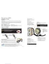
fixture with
dimmer attached
Dimmer retrofit kit
User interface
Three digit
display
DMX input
DMX thru
Status LED
Test
Plus
Minus
Lamp
burner

ETC Programming Guide
Source Four Dimmer/ES750/ES1
Source Four Dimmer Programming Guide Page 2 of 3 Electronic Theatre Controls, Inc.
Setting Intensity Level
• Pushing the test button will cause the fixture to enter test mode. This is true even if the current user
interface is showing the DMX channel on the display. The current 0-100% light output level will be
shown on the three digit screen. There is no time-out for test mode.
• Pressing and holding the test button will execute a test fade from 0-100%
• To exit test mode, press and release the test button. When exiting test mode the screen will go
blank, DMX control will be restored and the dimmer will return to the current DMX address.
RDM and User Interface Error Notifications
• Over Current Notification - Output wiring short
• No Load Notification - Lamp has burned out or has been removed
• Over-temp - Fixture has exceeded operating temperatures and will shut down
Switching Output Voltage
The dimmer can be configured to output 230V in place of the default 115V.
To view the current output voltage:
Step 1: Press and hold both the plus and minus buttons. The output voltage will be shown on the
three digit display.
To change the current output voltage:
Step 1: Press and hold both the plus and minus buttons.
Step 2: While holding the plus and minus buttons, hold down the test button. The voltage that you
will be changing to will appear blinking, then a 5-count, count down will be shown.
Once the countdown is complete, the new voltage will be applied and saved.
Note:
If data loss is detected, the lamp output will be held at the last level specified.
Note:
Dimmer will automatically re-enable when fixture is back within operational
temperature range. No user intervention is required to clear the error.
LED Status Indicator
LED Color Description
Solid Green Normal operation
Slow Blinking Green No DMX detected
Fast Blinking Green Invalid or incorrectly wired DMX
Solid Red Error condition exists
WARNING:
Make sure your lamp voltage matches your dimmer voltage. Default dimmer output
regulates to 115V at 100%. A dimmer set to 230V will damage a 115V lamp.

ETC Programming Guide
Source Four Dimmer/ES750/ES1
Source Four Dimmer Programming Guide Page 3 of 3 Electronic Theatre Controls, Inc.
Dimmer Curves
There are three available dimmer curves that can be set on the dimmer. These curves can only be set
through the RDM interface.
• ETC Modified Square - A more uniform response to control level changes. This is set as the
default curve.
• Preheat - Same as Modified Square but allows for a minimum level to be set to the curve to
maintain a warm lamp, reduce inrush and lengthen lamp life.
• Linear - matches control level increase to dimmer voltage 1:1.
Output Rating
Refer to the table below to determine the maximum wattage lamp you can use with your dimmer.
Input Voltage
Output Voltage
Setting
Maximum Wattage
115V 115V 750W
230V 115V 750W
230V 230V 1500W
WARNING:
The ES750 can ONLY be wired to tungsten lamps. Wiring to any other load type will
cause dimmer failure.
Note:
To maintain a correct dimmer curve, the dimmer must have a minimum load of 100W.
/