Page is loading ...

© Copyright 2006 Printed
Read the Operator’s manual entirely.
When you see this symbol, the
subsequent instructions and
warnings are serious - follow without
exception. Your life and the lives of
others depend on it!
!
Cover photo may show optional equipment not supplied
with standard unit.
Table of Contents
22195
311-252M
5/05/06
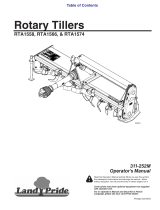
RTA10 & RTA15 Series
RTA1034, RTA1042, RTA1050 & RTA1058
RTA1542, RTA1550 & RTA1558
Rotary Tillers
Operator’s Manual

5/05/06
Land Pride
Table of Contents
© Copyright 2006 All rights Reserved
LandPride providesthispublication“asis”without warranty ofanykind,either expressed orimplied.Whileeveryprecaution has beentakeninthepreparation of thismanual,
Land Pride assumes no responsibility for errorsor omissions. Neither is any liability assumed for damages resulting fromthe use of the information contained herein. Land
Pride reserves the right to revise and improve its products as it sees fit. This publication describes the state of this product at the time of its publication, and may not reflect
the product in the future. The illustrations in this manual are not intended for safe and proper assembly or disassembly of equipment. The illustrations are intended for
ordering parts only.
Land Pride is a registered trademark.
All other brands and product names are trademarks or registered trademarks of their respective holders.
Printed in the United States of America.
RTA10 & RTA15 Series Rotary Tillers 311-252M
Important Safety Information . . . . . . . . . . .1
Safety at All Times . . . . . . . . . . . . . . . . . . . . . . . . . 1
Look For The Safety Alert Symbol . . . . . . . . . . . . .1
Safety Labels . . . . . . . . . . . . . . . . . . . . . . . . . . . . . 4
Introduction . . . . . . . . . . . . . . . . . . . . . . . .7
Application . . . . . . . . . . . . . . . . . . . . . . . . . . . . . . . 7
Using This Manual . . . . . . . . . . . . . . . . . . . . . . . . . 7
Terminology . . . . . . . . . . . . . . . . . . . . . . . . . . .7
Definitions . . . . . . . . . . . . . . . . . . . . . . . . . . . . . 7
Owner Assistance . . . . . . . . . . . . . . . . . . . . . . . . . 7
Serial Number Plate . . . . . . . . . . . . . . . . . . . . .7
Further Assistance . . . . . . . . . . . . . . . . . . . . . . 7
Section 1 Assembly and Set-Up . . . . . . . .8
Tractor Requirements . . . . . . . . . . . . . . . . . . . . . . 8
Hitch and Driveline Guard . . . . . . . . . . . . . . . . . . .9
Leg Stand Assembly . . . . . . . . . . . . . . . . . . . . . . . 9
Tractor Hook-Up . . . . . . . . . . . . . . . . . . . . . . . . . .9
Driveline Installation . . . . . . . . . . . . . . . . . . . . . . . 10
Checking Driveline Minimum Length . . . . . . . . 10
Checking Driveline Maximum Length . . . . . . . 11
Section 2 Operating . . . . . . . . . . . . . . . . .12
General Notes for Field Operations . . . . . . . . . . . 12
Operating Check List . . . . . . . . . . . . . . . . . . . . 12
Transporting . . . . . . . . . . . . . . . . . . . . . . . . . . . . 12
Parking . . . . . . . . . . . . . . . . . . . . . . . . . . . . . . . . 13
Operating Instructions . . . . . . . . . . . . . . . . . . . . . 13
Section 3 Adjustments . . . . . . . . . . . . . . .14
RTA10 Tiller Hitch Offset . . . . . . . . . . . . . . . . . . . 14
RTA15 Tiller Hitch Sideshift . . . . . . . . . . . . . . . . . 14
Drive Chain . . . . . . . . . . . . . . . . . . . . . . . . . . . . . 15
Rear Deflector . . . . . . . . . . . . . . . . . . . . . . . . . . . 15
Skid Shoe . . . . . . . . . . . . . . . . . . . . . . . . . . . . . . 16
Section 4 Maintenance and Lubrication .17
Maintenance . . . . . . . . . . . . . . . . . . . . . . . . . . . .17
Tine Replacement . . . . . . . . . . . . . . . . . . . . . . . .17
Driveline Protection . . . . . . . . . . . . . . . . . . . . . . .17
Clutch Run-In . . . . . . . . . . . . . . . . . . . . . . . . . . . .17
Clutches With 8-Hex Head Socket Bolts . . . . .17
Clutches With 4-Tightening Nuts . . . . . . . . . . .17
Clutch Disassembly & Reassembly . . . . . . . . . . .18
Clutches With 8-Hex Head Socket Bolts . . . . .18
Clutches With 4-Tightening Nuts . . . . . . . . . . .19
Storage . . . . . . . . . . . . . . . . . . . . . . . . . . . . . . . .20
Lubrication . . . . . . . . . . . . . . . . . . . . . . . . . . . . . .21
Driveline U-Joint . . . . . . . . . . . . . . . . . . . . . . .21
Driveline Shaft . . . . . . . . . . . . . . . . . . . . . . . . .21
Chaincase . . . . . . . . . . . . . . . . . . . . . . . . . . . .21
Bearing On Right End Of Rotor Shaft . . . . . . .22
Side Plug Gearbox . . . . . . . . . . . . . . . . . . . . .22
Top Plug Gearbox (10 Series) . . . . . . . . . . . . .22
Top Plug Gearbox (15 Series) . . . . . . . . . . . . .22
Section 5 Specifications and Capacities 23
RTA10 Series Rotary Tiller . . . . . . . . . . . . . . . . . .23
RTA15 Series Rotary Tiller . . . . . . . . . . . . . . . . . .23
Section 6 Features and Benefits . . . . . . .24
RTA10 Series Rotary Tiller . . . . . . . . . . . . . . . . . .24
RTA15 Series Rotary Tiller . . . . . . . . . . . . . . . . . .25
Section 7 Troubleshooting . . . . . . . . . . .26
Section 8 Appendix . . . . . . . . . . . . . . . . .27
Torque Values Chart . . . . . . . . . . . . . . . . . . . . . .27
Notes . . . . . . . . . . . . . . . . . . . . . . . . . . . . . . . . . .28
Warranty . . . . . . . . . . . . . . . . . . . . . . . . . . . . . . .29
Table of Contents

1
5/05/06
RTA10 & RTA15 Series Rotary Tillers 311-252M
Land Pride
Important Safety Information
Table of Contents
Important Safety Information
These are common practices that may or may not be applicable to the products described in
this manual.
▲
Safety at All Times
Thoroughly read and understand
the instructions given in this
manual before operation. Refer to
the “Safety Label” section, read
all instructions noted on them.
Do not allow anyone to operate
this equipment who has not fully
read and comprehended this
manual and who has not been
properly trained in the safe
operation of the equipment.
▲ Operator should be familiar with
all functions of the unit.
▲ Operate implement from the
driver’s seat only.
▲ Do not leave tractor or implement
unattended with engine running.
▲ Dismounting from a moving
tractor could cause serious injury
or death.
▲ Do not stand between the tractor
and implement during hitching.
▲ Keep hands, feet, and clothing
away from power-driven parts.
▲ Wear snug fitting clothing to avoid
entanglement with moving parts.
▲ Watch out for wires, trees, etc.,
when raising implement. Make
sure all persons are clear of
working area.
▲ Turning tractor too tight may
cause implement to ride up on
wheels. This could result in injury
or equipment damage.
!
Look For The Safety Alert Symbol
The SAFETY ALERT SYMBOL indicates there is a
potential hazard to personal safety involved and extra
safety precaution must be taken. When you see this
symbol, be alert and carefully read the message that
follows it. In addition to design and configuration of
equipment, hazard control and accident prevention
are dependent upon the awareness, concern,
prudence and proper training of personnel involved in
the operation, transport, maintenance and storage of
equipment.
Be Aware of
Signal Words
A Signal word designates a degree or
level of hazard seriousness. The
signal words are:
Indicates an imminently hazardous
situation which, if not avoided, will
result in death or serious injury. This
signal word is limited to the most
extreme situations, typically for
machine components that, for
functional purposes, cannot be
guarded.
!
DANGER
Indicates a potentially hazardous
situation which, if not avoided, could
result in death or serious injury, and
includes hazards that are exposed
when guards are removed. It may also
be used to alert against unsafe
practices.
Indicates a potentially hazardous
situation which, if not avoided, may
result in minor or moderate injury. It
may also be used to alert against
unsafe practices.
!
WARNING
!
CAUTION
For Your Protection
▲ Thoroughly read and understand
the “Safety Label” section, read all
instructions noted on them.
Shutdown and Storage
▲ Lower machine to ground, put
tractor in park, turn off engine, and
remove the key.
▲ Detach and store implements in a
area where children normally do
not play. Secure implement by
using blocks and supports.
OFF
REMO
VE

2
RTA10 & RTA15 Series Rotary Tillers 311-252M
5/05/06
Land Pride
Important Safety Information
Table of Contents
Transport
Machinery Safely
▲ Comply with state and local laws.
▲ Maximum transport speed for
implement is 20 mph. DO NOT
EXCEED. Never travel at a speed
which does not allow adequate
control of steering and stopping.
Some rough terrain require a
slower speed.
▲ Sudden braking can cause a
towed load to swerve and upset.
Reduce speed if towed load is not
equipped with brakes.
▲ Use the following maximum
speed - tow load weight ratios as
a guideline:
▲ 20 mph when weight is less than
or equal to the weight of tractor.
▲ 10 mph when weight is double
the weight of tractor.
▲ IMPORTANT: Do not tow a load
that is more than double the
weight of tractor.
Use Safety
Lights and Devices
▲ Slow moving tractors, self-
propelled equipment, and towed
implements can create a hazard
when drivenon publicroads. They
are difficult to see, especially at
night.
▲ Flashing warning lights and turn
signals are recommended
whenever driving on public roads.
Use lights and devices provided
with implement.
Practice Safe Maintenance
▲ Understand procedure before
doing work. Use proper tools and
equipment, refer to Operator’s
Manual for additional information.
▲ Work in a clean dry area.
▲ Lower the implement to the
ground, put tractor in park, turn off
engine, and remove key before
performing maintenance.
▲ Allow implement to cool
completely.
▲ Do not grease or oil implement
while it is in operation.
▲ Inspect all parts. Make sure parts
are in good condition & installed
properly.
▲ Remove buildup of grease, oil or
debris.
▲ Remove all tools and unused
parts from implement before
operation.
These are common practices that may or may not be applicable to the products described in
this manual.
Keep Riders
Off Machinery
▲ Riders obstruct the operator’s
view, they could be struck by
foreign objects or thrown from the
machine.
▲ Never allow children to operate
equipment.

3
5/05/06
RTA10 & RTA15 Series Rotary Tillers 311-252M
Land Pride
Important Safety Information
Table of Contents
Prepare for Emergencies
▲ Be prepared if a fire starts.
▲ Keep a first aid kit and fire
extinguisher handy.
▲ Keep emergency numbers for
doctor, ambulance, hospital and
fire department near phone.
911
Wear
Protective Equipment
▲ Protectiveclothingand equipment
should be worn.
▲ Wear clothing and equipment
appropriate for the job. Avoid
loose fitting clothing.
▲ Prolonged exposure to loud noise
can cause hearing impairment or
hearing loss. Wear suitable
hearing protection such as
earmuffs or earplugs.
▲ Operating equipment safely
requires the full attention of the
operator. Avoid wearing radio
headphones while operating
machinery.
Avoid High
Pressure Fluids Hazard
▲ Escaping fluidunderpressure can
penetratethe skincausingserious
injury.
▲ Avoid the hazard by relieving
pressure before disconnecting
hydraulic lines.
▲ Use a piece of paper or
cardboard, NOT BODY PARTS, to
check for suspected leaks.
▲ Wear protective gloves and safety
glasses or goggles when working
with hydraulic systems.
▲ If an accident occurs, see a
doctor immediately. Any fluid
injected into the skin must be
surgically removed within a few
hours or gangrene may result.
These are common practices that may or may not be applicable to the products described in
this manual.

4
RTA10 & RTA15 Series Rotary Tillers 311-252M
5/05/06
Land Pride
Important Safety Information
Table of Contents
Safety Labels
1. Your tiller comes equipped with all safety labels in place.
They were designed to help you safely operate your mower.
Read and follow their directions.
2. Keep all safety labels clean and legible.
3. Replace all damagedor missinglabels. To order new labels
go to your nearest Land Pride dealer.
4. Some new equipmentinstalledduring repair requiressafety
labels to be affixed to the replaced component as specified
by Land Pride. When ordering new components make sure
the correct safety labels are included in the request.
5. Refer to this section for proper label placement.
To install new labels:
a. Clean the area the label is to be placed.
b. Spray soapy water on the surface where the label is to
be placed.
c. Peel backing from label. Press firmly onto the surface.
d. Squeeze out air bubbles with the edge of a credit card.
818-130C
Operate only w/540 rpm PTO
22196
Model RTA10
Model RTA15
818-171C
Rotating Tines Hazard!
22195
Model RTA10
Model RTA15


7
5/05/06
RTA10 & RTA15 Series Rotary Tillers 311-252M
Land Pride
Introduction
Table of Contents
Introduction
The parts on your RTA10 or RTA15 Rotary Tiller have
been specially designed and should only be replaced
with genuine Land Pride parts. Therefore, should your
Rotary Tiller require replacement parts go to your Land
Pride Dealer.
Serial Number Plate
For prompt service always use the serial number and
modelnumberwhen ordering partsfromyour LandPride
dealer.Besuretoinclude yourserialandmodelnumbers
incorrespondencealso. Refer to Figure 1 forthelocation
of your serial number plate
.
Serial Number Plate Location
Figure 1
Further Assistance
Your dealer wants you to be satisfied with your Rotary
Tiller. If for any reason you do not understand any part of
thismanualorare not satisfied with theservicereceived,
the following actions are suggested:
1. Discuss the matter with your dealership service
manager making sure he is aware of any problems
you may have and that he has had the opportunity to
assist you.
2. If you are still not satisfied, seek out the owner or
general manager of the dealership, explain the
problem and request assistance.
3. For further assistance write to:
Land Pride
Service Department
P.O. Box 5060
Salina, KS 67402-5060
E-mail address
lpser[email protected]
Land Pride welcomes you to the growing family of new
product owners.
Thisrotary tiller has beendesignedwithcareand builtby
skilledworkersusing qualitymaterials.Properassembly,
maintenance, and safe operating practices will help you
get years of satisfactory use from the machine.
Application
The RTA10 and RTA15 Series Rotary Tillers are
designed and built by Land Pride to till the soil for
seedbed or planting preparation. Both models are
adapted for three-point hitch Category 1 mounting. The
RTA10 has a 17-25 horsepower tractor requirement,
while the RTA15 has a 17-35 horsepower requirement.
These Land Pride Tillers have uses and applications in
landscaping, nurseries, gardens, and light commercial
use. See “Features and Benefits”, “Section 6” for
additional information.
Using This Manual
• This Operator’s Manual is designed to help familiarize
you with safety, assembly, operation, adjustments,
troubleshooting, and maintenance. Read this manual
and follow the recommendations to help ensure safe
and efficient operation.
• The information contained within this manual was
current at the time of printing. Some parts may change
slightly to assure you of the best performance.
• To order a new Operator or Parts Manual contact your
authorized dealer. Manuals can also be downloaded,
free-of-charge from our website at www.landpride.com
or printed by your dealer from the Land Pride Service &
Support Center CD-Rom.
Terminology
“Right” or “Left” as used in this manual is determined by
facing the direction the machine will operate while in use
unless otherwise stated.
Definitions
Owner Assistance
The Warranty Registration card should be filled out by
the dealer at the time of purchase. This information is
necessary to provide you with quality customer service.
If customer service or repair parts are required contact a
LandPridedealer.A dealerhastrainedpersonnel,repair
parts and equipment needed to service the implement.
NOTE: Aspecialpointofinformationthattheoperator
must be aware of before continuing.
IMPORTANT: A specialpointofinformation related to
its preceding topic. Land Pride’s intention is that this
information should be read and noted before
continuing.

8
RTA10 & RTA15 Series Rotary Tillers 311-252M
5/05/06
Land Pride
Section 1 Assembly and Set-Up
Table of Contents
Section 1 Assembly and Set-Up
!
CAUTION
To avoid bodily injury caused by accidental falling of tiller,
securely support tiller on safe supporting stands or blocks!
This unit is shipped almost completely assembled.
Carefully follow instructions for final assembly.
Before attempting assembly check the following items.
Having all the needed parts and equipment readily at
hand will speed up your assembly task and will make the
job as safe as possible.
• Check for fasteners and pins that were shipped with the
tiller. All hardware coming from the factory has been
installed in the location where it will be used. If a part or
fastener is temporarily removed for assembly reasons,
remember where it goes. Keep the parts separated.
• Have a fork lift or loader along with chains and safety
stands that are sized for the job ready for the assembly
task.
• Have a minimum of 2 people at hand during assembly.
• Check to see that all nuts are tightened. Refer to the
Torque Values Chart in the “Appendix” section on
page 27.
Tractor Requirements
This tiller is designed with a 3-point category l hitch.
Horse power rating of the tractor should not exceed 25
PTO horsepower for the 10 Series Rotary Tiller and not
to exceed 35 PTO horsepower for the 15 Series.
!
CAUTION
Do not over speed PTO or machine damage may result. This
tiller is designed to be used with a tractor using a 540 rpm rear
PTO.
NOTE: In order to maintain steering control, ballast
may have to be added to your tractor. To determine
whether or not to add ballast, refer to your tractor
operator’s manual.
14163
Assembly Illustration
Figure 1-1

9
5/05/06
RTA10 & RTA15 Series Rotary Tillers 311-252M
Land Pride
Section 1 Assembly and Set-Up
Table of Contents
Hitch and Driveline Guard
Refer to Figure 1-1:
1. Install both top 3-point hitch plates (#6 and #7) to
outside of gearbox mounting frame with 5/8” x 1 1/2”
long bolts (#3), 5/8” lockwashers (#4), and 5/8” nuts
(#5). Do not tighten hardware at this time.
2. Install spacer (#9) between upper 3-point hitch plates
(#6 & #7) with 5/8” x 3 1/2” long bolt (#8).
3. Securely tighten all bolts. Refer to the Torque Values
Chart in the “Appendix” section on page 27.
4. Install driveline guard (#10) to the top of the 3-point
hitch plates with four 1/4” wing screws (#11).
Leg Stand Assembly
Refer to Figure 1-1:
1. Insert leg stand (#13) into leg stand holder on the end
of the tiller frame.
2. Adjust to the desired height and pin with 1/4” x 1 3/4”
long wire lock pin (#14).
NOTE: Remove driveline guard for easier access to
the driveline at the gearbox.
IMPORTANT: The three upper holes are used for
parking thetiller and the bottom hole is usedwhen the
tiller is in use.
Tractor Hook-Up
Refer to Figure 1-2:
1. When using tractors with multi-speedPTO, be certain
PTO is set for 540 rpm.
2. Back tractor up to tiller until lower 3-Point links are
aligned with hitch clevises on tiller.
3. Secure the tractor’s 3-Point lower links to the lower
hitch clevises using 7/8" diameter hitch pins.
4. Secure the tractor’s top link to the tiller top hitch using
a 3/4" diameter hitch pin (supplied by customer).
Adjust tractor top link in order to level the tiller.
5. Adjust the tractor’s 3-Point hitch lift height so that the
tiller tines are not lifted more than 14 inches off the
ground to prevent damage to the driveline u-joints.
!
WARNING
Lifting unit more than 14” high while PTO is engaged may
damage driveline components.
Tractor Hook-Up
Figure 1-2
10134
22191

10
RTA10 & RTA15 Series Rotary Tillers 311-252M
5/05/06
Land Pride
Section 1 Assembly and Set-Up
Table of Contents
Driveline Installation
Refer to Figure 1-3, Figure 1-4 and Figure 1-5
Thetillerdrivelineiscoupledtothetractorandimplement
shafts with either push pin couplers, pull collar couplers
or a combination of both and with either a shear bolt or
slip clutch on one end for protection from shock loads.
Always engage the PTO at low engine rpm to minimize
start-up torque on the driveline. Drivelines with friction
clutches must go through a “run-in” operation prior
to initial use and after long periods of inactivity. See
“Section 4 Maintenance and Lubrication” on page 17 for
a detailed description of maintaining the driveline.
!
CAUTION
Tractor PTO shield and all tiller guards must be in place at all
times during operation!
Checking Driveline Minimum Length
Refer to Figure 1-1 on page 8:
1. Start tractor and slowly engage tractor’s hydraulic
3-point to lift the lower arms until the Rotary Tiller’s
driveline shaft is approximately level with tractor's
PTO shaft.
2. Slide the slip clutch or shear bolt yoke end of driveline
(#12) over the splined input shaft of gearbox (#1).
Secure with driveline yoke locking device.
3. Slidetheoppositedrivelineyoke endoverthetractor’s
splined driveline shaft. Secure with driveline yoke
locking device. Skip to step 4 if driveline fits between
tractor and implement.
Refer to Figure 1-6 on page 11:
4. The driveline will require shortening if it is too long to
fit between the tractor and tiller gearbox. Shorten
driveline as follows:
a. Raise 3-point lower arms until tiller and tractor
PTO shafts are approximately level with each
other. Securely block Rotary Tiller frame in this
position. Set tractor in park, shut tractor engine
off, set park brake and remove switch key.
IMPORTANT: Always check driveline maximum and
minimum length during initial setup, when connecting
to a different tractor and when alternating between
using a quick hitch and a standard 3-point hitch. More
than one driveline may be required to fit all
applications.
IMPORTANT: Itis necessarytoaligningthe tractor’s
PTO shaftlevelwithtiller’sPTOshaftwhenchecking
to see if the driveline’s minimum length is correct.
Toolongadriveline candamagethetractor,gearbox
and driveline.
IMPORTANT: For easier access to gearbox input
shaft, remove driveline guard (#10).
Figure 1-3
Figure 1-4
Figure 1-5
Implement End
Tractor End
Push Pin Coupling
Push Pin Coupling
With
Shear Bolt Protection
22232
Implement End
Tractor End
Pull Collar Coupling
Push Pin Coupling
With
Shear Bolt Protection
22233
Implement End
Tractor End
Push Pin
Coupling
Pull Collar Coupling
With
Slip Clutch Protec-
22234

11
5/05/06
RTA10 & RTA15 Series Rotary Tillers 311-252M
Land Pride
Section 1 Assembly and Set-Up
Table of Contents
b. Pull driveline apart into two sections as shown in
Figure 1-6. Attach the outer driveline universal
joint to the tractor shaft and inner driveline
universal joint to the tiller gearbox shaft. Pull on
each driveline section to be sure the universal
joints are secured to the shafts.
c. Hold driveline sections parallel to each other to
determineiftheyaretoolong.Theinnerandouter
shieldsoneachsectionshouldendapproximately
1" short of reaching the universal joint shield on
the adjacent section (see “B” dimension). If they
are too long, measure 1" (“B” dimension) back
fromtheuniversaljointshieldand make a mark at
this location on the inner and outer driveline
shields.
d. Cut off inner shield at the mark (“X” dimension).
Cut the same amount off the inner shaft (“X1”
dimension). Repeat cut off procedure (“Y”&“Y1”
dimensions) to the outer driveline half.
e. Remove all burrs and cuttings.
Shortening the driveline
Figure 1-6
Checking Driveline Maximum Length
Make sure you have gone through the steps in
"Checking Driveline Minimum Length" on page 10
before checking maximum length.
Refer to Figure 1-7
The driveline maximum length must, when fully
extended,haveaminimumoverlapoftheprofiletubesby
notlessthan1/3the free length withbothinnerandouter
profile tubes being of equal length.
1. Apply multi-purpose grease to the inside of the outer
shaft and reassemble the driveline.
2. Assemble the two driveline profiles together with just
1/3overlappingof theprofiletubesasshownin Figure
1-7. Measure and record this overall length for
checking driveline length in step 9 below.
13588
3. Attach inner driveline yoke end to the tiller gearbox
input shaft.
4. Attach outer driveline yoke end to the tractor's PTO
shaft.
5. The driveline should now be moved back and forth to
insure that both ends are secured to the tractor and
Rotary Tiller PTO shafts. Reattach any end that is
loose.
Driveline Maximum Length
Figure 1-7
6. Hook driveline safety chain in the hole in the inner
drivelineguard.Attachtheotherendtothetiller’smain
frame.
7. Start tractor and raise tiller just enough to remove
blocks used to support the tiller frame in step 3a on
page 10.
8. Slowly engage tractor’s hydraulic 3-point to lower the
Rotary Tiller. Check for sufficient drawbar clearance.
Move drawbar ahead, aside or remove if required.
9. Raise and lower implement to find maximum
extended driveline length. Check to makecertain that
the driveline overall length does not extend beyond
the maximum recorded length in step 2.
24513
Outer Shielding has been removd for clarity.
IMPORTANT: A small chain is supplied with the
driveline. This chain must be attached to the inner
driveline shield and to the tiller to restrict shield
rotation.

12
RTA10 & RTA15 Series Rotary Tillers 311-252M
5/05/06
Land Pride
Section 2 Operating
Table of Contents
General Notes for Field Operations
Before beginning to till, the following inspection should
be performed:
1. Checkoillevel ingearboxandchaincase. Refertothe
Lubrication portion of the “Maintenance and
Lubrication” section on page 21.
10. Check that all plugs have been replaced properly in
the gearbox and chaincase.
11. Check drive chain tension. Refer to the Drive Chain
portion of the “Adjustments” section on page 15.
12. Be sure all tiller tines, bolts and nuts are tight.
13. Be certain all guards and shields are in place and
secure.
14. Grease PTO shaft and all other grease fittings. Refer
to the Lubrication portion of the “Maintenance and
Lubrication” section on page 21.
15. Cleartheareatobetilledofrocks,branchesandother
foreign objects.
16. Tall grass and weeds should be mowed before tilling.
17. Operate with 540 rpm PTO tractor.
18. At first begin tilling at a slow forward speed and shift
up as ground conditions warrant.
19. Tiller should be operated with the tiller deck level to
the ground.
20. Tiller tineswillcutbetter atafasterrotorspeedthan at
reduced throttle.
21. Do not engage PTO at full throttle.
22. Tilling should not be done in wet conditions as soil will
stick to tines.
23. After tilling the first 50 feet,stop and check to see that
the tiller is adjusted properly.
24. Do not make sharp turns or attempt to back up while
tiller is in the ground.
25. Do not engagePTO with machineinthefullyraised or
lowered position.
26. Periodicallycheckforforeignobjectswrappedaround
the rotor shaft and remove them after disengaging
PTO, turning off tractor, and removing ignition key.
Operating Check List
In addition to design and configuration of
equipment, hazard control and accident prevention
are dependent upon the awareness, concern,
prudence and proper training involved in its
operation, transport, maintenance and storage of
equipment.Beforebeginningoperationthe following
inspections should be performed.
Transporting
!
CAUTION
When traveling on public roads whether at night or during the
day, use accessory light and devices for adequate warning to
operators of other vehicles. Comply with all federal, state and
local laws.
1. When raising the tiller to the transport position, be
sure that the drivelinedoesnotcontacttractoror tiller.
Adjust the tractor’s 3-point hitch lift height so that the
tiller tines are not lifted more than 14 inches off the
ground to prevent damage to the driveline.
2. Be sure to reduce tractor groundspeed when turning,
and leave enough clearance so the tiller does not
contact obstacles such as buildings, trees or fences.
3. Select a safe ground travel speed when transporting
from one area to another. When traveling on
roadways, transport in such a way that faster moving
vehicles may pass you safely.
4. When traveling over rough or hilly terrain, shift tractor
to a lower gear.
Read and follow the “Important Safety Information” section
on starting on page 1 carefully.
ReadallofTractor Hookupin the“Assembly andSetup” section
on page 9.
Read all of the “Operating Instructions” section on page 12.
Lubricate the tiller as needed. Refer to the Lubrication portion of
the “Maintenance and Lubrication” section on page 17.
Check the tiller initially and periodically for loose bolts & pins,
using the Torque Values Chart in the “Appendix” section on
page 27.
Make sure all guards and shields are in place.
Check initially and periodically for loose bolts, pins, and chains.
IMPORTANT: Always disengage the driveline before
raising the tiller to transport position.
Section 2 Operating

13
5/05/06
RTA10 & RTA15 Series Rotary Tillers 311-252M
Land Pride
Section 2 Operating
Table of Contents
Parking
Thefollowingstepsshould bedonewhen preparing tostore
thetillerorunhitchitfromthetractor.SeealsoStorageinthe
“Maintenance and Lubrication” section on page 20 for
additional information on long term storage of your tiller.
1. Park the tiller on a level, solid area.
2. Shut off tractor engine and engage parking brake.
3. Setparking stand to desired heighttomaintaintillerin
proper height for re-hook-up and install pin to lock in
place.
4. Unhitch from tractor.
5. See Storage in the “Maintenance and Lubrication”
sectiononpage20iftillerisnotgoingtobeusedforan
extended period of time.
Operating Instructions
Before using your Land Pride RTA10 or RTA15 Series
Rotary Tiller, you should have completely read the
Operator’s Manual, properly attached the Tiller to the
tractor, cut the driveline to proper length, Run-in the
clutch, and gone through the Operating Checklist. If you
have missed any of these steps, please complete them
before proceeding.
Now that you have properly prepared yourself and your
tiller,it’stimetodo some tilling. Carefullydrivethe tractor
to the site where you intend to till. You should have
already cleaned this site of any large limbs, rocks,
trash, metal or other debris. Best results will be
achievedifyou have mounted yourtiller offset totheright
far enough to cover the tread of your right tractor wheel.
Linethetractorupjusttotheright ofcenter onyourtillage
plot. You will be working from the center out and always
turning to the right to line up for your next pass.
Lower the tiller half way to the ground and reduce your
tractor engine speed to about one quarter throttle.
Engage the PTO and gradually increase the engine
speed until you reach full PTO speed of 540 rpm. Lower
the Tiller to the ground and simultaneously commence
forward travel of approximately 2 mph.
Travel about 50 ft. and then stop to check your results.
When stopping, remember to lift the tiller out of the
ground, stop the tractor, reduce engine speed,
disengage the PTO, set the park brake, shut off the
tractor, and remove the keys. If youare tilling too shallow
or too deep, adjust the skid shoes accordingly. If the soil
texture is too coarse, lower the leveling door and reduce
your ground speed. If the soil texture is too fine, you will
need to raise your leveling door and increase your
groundspeed.Foranyotherproblemconditionsthatmay
arise,youwillwanttorefertotheTroubleshootingsection
on page 26.
When you are done tilling forthe day, make sure youuse
propertractorshut downprocedures beforeyouget offof
the tractor. If youaredetachingyourtiller,make sure you
park it on a dry and level surface leaving it clean and
ready for the next use. When you put your tiller up forthe
season,make sureyou refertotheStorageDirectionson
page 20.
With a little practiceandafew adjustments,you will soon
be achieving the results you want with your Land Pride
RotaryTiller.See“FeaturesandBenefits” Section6or
“Specifications and Capacities” Section 5 for
additional information and performance enhancing
options.

14
RTA10 & RTA15 Series Rotary Tillers 311-252M
5/05/06
Land Pride
Section 3 Adjustments
Table of Contents
Section 3 Adjustments
RTA10 Tiller Hitch Offset
Refer to Figure 3-1:
By shifting the lower hitch clevises (#1) to the side, a
limited amount of offset can be obtained.
!
CAUTION
After offsetting check to seethat the PTO shaft clears all shields
on the tiller, tractor and the tiller hitch. If not, decrease the
offset until clearance is obtained.
RTA Tiller Hitch Offset
Figure 3-1
15219
RTA15 Tiller Hitch Sideshift
Refer to Figure 3-2:
Thethreepoint and gearboxcan besideshiftedtothe left
of tiller center for various working conditions.
!
CAUTION
After sideshifting check to see that the PTO shaft clears all
shields on the tiller, tractor and the tiller hitch. If not, decrease
the sideshift until clearance is obtained.
6. Loosen the two u-bolts (#2) which hold the top
hitch/gearbox frame (#1) to the front tube.
7. Loosen the two bolts (#3) which hold the top
hitch/gearbox frame (#1) to the rear of the tiller.
8. Loosenthetwou-bolts (#4) which hold the lowerhitch
clevises (#5) to the front tube.
9. Slide the top hitch/gearbox assembly to the desired
location.
10. Re-center the lower hitch clevises with respect to the
gearbox.
Retighten all bolts and nuts referring to the Torque
Values Chart in the “Appendix” section on page 27.
NOTE: For maximum offset, the left lower hitch
clevis can be located on the left hand side of the left
end plate.
RTA15 Tiller Hitch Sideshift
Figure 3-2
22192

15
5/05/06
RTA10 & RTA15 Series Rotary Tillers 311-252M
Land Pride
Section 3 Adjustments
Table of Contents
Drive Chain
Refer to Figure 3-3:
The tension on the drive chain can be easily adjusted by
using the chain tightener stud. Should backlash occur,
loosen the nut and torque the stud clockwise to 20 - 30
foot pounds and tighten nut to 400 foot pounds.
Rear Deflector
Refer to Figure 3-4:
Thereardeflectorcanbeadjustedclosertothegroundto
produce a fine soil texture or can be raised to produce a
coarse soil texture by adjusting the chain length (#1) on
the rear deflector.
Chain Tightener
Figure 3-3
10135
Rear Deflector
Figure 3-4
22193

16
RTA10 & RTA15 Series Rotary Tillers 311-252M
5/05/06
Land Pride
Section 3 Adjustments
Table of Contents
Skid Shoe
Refer to Figure 3-5:
The skid shoes can be raised or lowered for the desired
tilling depth by:
1. Raise tiller off the ground and properly support.
2. Loosen pivot bolt (#1) on front of shoe.
3. Remove adjusting bolt (#2) on rear of shoe.
4. Adjust skid (#3) shoe to desired location.
5. Install adjusting bolt, and tighten both the adjusting
bolt and the pivot bolt.
IMPORTANT: Be sure both skid shoes are adjusted
the same.
Skid Shoe Adjustment
Figure 3-5
11021

17
5/05/06
RTA10 & RTA15 Series Rotary Tillers 311-252M
Land Pride
Section 4 Maintenance and Lubrication
Table of Contents
Section 4 Maintenance and Lubrication
Maintenance
!
CAUTION
For safety reasons, each maintenance operation must be
performed with the tractor’s PTO disengaged, the Tiller
lowered completely to the ground or on safely supported
blocking, tractor engine shut off and ignition key removed.
Properservicing andadjustmentis thekeytothelong life
of any farm implement. With careful and systematic
inspection, you can avoid costly maintenance, time and
repair.
After using your tiller for several hours, check all bolts to
be sure they are tight.
Replace any worn, damaged or illegible safety labels by
obtaining new labels form your Land Pride Dealer.
Tine Replacement
Refer to Figure 4-1:
TIne Replacement
Figure 4-1
6. Remove 2 cap screws and fasteners from tine to be
replaced. Remove tine.
7. Install new tine on side of attaching flange as shown.
8. Replace 2 cap screws and fasteners and tighten nuts
to proper torque. See The Torque Values Chart in the
“Appendix” section on page 27.
!
WARNING
Worn tines may be very sharp!
10136
IMPORTANT: Always install tine with cutting edge
facing direction of rotor shaft rotation. When ordering
replacement tines, be sure to order both right and left
hand tines.
IMPORTANT: Replace tines with genuine Land Pride
tines only.
Driveline Protection
Tiller drive components are protected from shock loads
by either a two plate friction clutch or a shear bolt. Avoid
shear bolt failure by engaging the PTO slowly at low
engine rpm. See your Land Pride Dealer when replacing
shear bolts. Torque shear bolt nuts to 7-9 ft. lbs.
Friction clutches should be “run-in” prior to initial
operation and after long periods of inactivity. You may
have one of twotypesoffriction clutches. Refer to Figure
4-2 and Figure 4-3 page 18 to determine which friction
clutch your Rotary Tiller has. Follow “Clutch Run-In”
instructions for your particular tiller.
To prevent driveline and gearbox damage, repeat
“Run-In” instructions at the beginning of each season
andwhenmoisture and/or condensationseizesthe inner
friction plates.
Clutch Run-In
Clutches With 8-Hex Head Socket Bolts
Refer to Figure 4-2 on page 18
1. Loosen counterclockwise all 8 hex head socket bolts
uniformly 6 full turns.
2. Cycle clutch on and off 5 or 6 times (15 seconds on
and 15 seconds off) with the engine operating at half
throttle. Disengage driveline, shut off tractor and
remove key. Wait for all components to stop before
dismounting from tractor.
3. Tighten hex head socket bolts fully back. Clutch is
ready for use
4. The clutch should be checked during the first hour of
cutting and periodically each week.
Clutches With 4-Tightening Nuts
Refer to Figure 4-3 on page 18 (View - A):
1. Using a pencil or other marker, scribe a line across the
exposed edges of the clutch plates and friction disks.
2. Tighten all 4 nuts uniformly until the spring load is low
enough that the clutch slips freely with the PTO
engaged.
3. Start the tractor and engage driveline drive for 2-3
seconds to permit slippage of the clutch surfaces.
Disengage the driveline, then re-engage a second
time for 2-3 seconds. Disengage driveline, shut off
tractor and remove key. Wait for all components to
stop before dismounting from tractor.
Shear Bolt and Lock Nut Part Numbers
Part No. Part Description
RTA10
802-267C M6 x 35 GR 8.8
803-154C M6 Lock Nut (Torque nut to 7-9 ft. lbs.)
RTA15
802-115C 5/16”-18 GR 5 bolt.
803-011C 5/16”-18 Lock Nut (Torque nut to 7-9 ft. lbs.)

18
RTA10 & RTA15 Series Rotary Tillers 311-252M
5/05/06
Land Pride
Section 4 Maintenance and Lubrication
Table of Contents
4. Inspect the clutch and ensure that the scribed
markings made on the clutch plates have changed
position. Slippage has not occurred if any two marks
on the friction disk and plate are still aligned. A clutch
that has not slipped must be disassembled to
separate the friction disk plates. See Clutch
Disassembly & Reassembly on page 19.
Refer to Figure 4-3 (View - B):
5. Turnall4nutsfullyback if no two marksonthefriction
disk and plate are still aligned. Clutch is ready for use.
6. The clutch should be checked during the first hour of
cutting and periodically each week. An additional set
of scribe marks can be added to check for slippage.
Clutch Run-In With 8- Hex Head Socket Bolts
Figure 4-2
Clutch Run-In With 4 Tightening Nuts
Figure 4-3
Clutch Disassembly & Reassembly
Clutches With 8-Hex Head Socket Bolts
Refer to Figure 4-4
If the clutch run-in procedure, see Clutches With 8-Hex
HeadSocketBolts,indicatedthatoneormoreofthefriction
disks did not slip, then the clutch must be disassembled to
separate the friction disks.
1. Rotate 8 hex head socket bolts (#4) all the way out to
free stop flange (#5).
2. Rotate stop flange (#5) and removefrom housing (#1)
3. Remove the following inner components:
a. Spring kit (#6)
b. Pressure flange (#7)
c. 1st Friction Disc (#8)
d. Hub with flange and pull collar (#2 & #3)
e. 2nd Friction disc (#8)
f. Bearing (#9)
4. Inspect all components and replace to their original
position. Make certain stop flange (#5) is replaced
with its flanges down as shown.
5. Fully tighten all 8 hex head socket bolts (#4).
Clutch Assembly
Figure 4-4
Hex Head
Socket Bolts
21270
22171
21302
/