Page is loading ...

1
INSTALLATION AND OPERATION MANUAL
1645 Lemonwood Dr.
Santa Paula, CA. 93060, USA
Toll Free 1-800-253-2363
Tel: 1-805-933-9970
Fax: 1-805-933-9160
wwwbendpak.com
IMPORTANT SAFETY INSTRUCTIONS
SAVE THESE INSTRUCTIONS
PLEASE READ THE ENTIRE CONTENTS OF THIS MANUAL PRIOR TO INSTALLATION
AND OPERATION. BY PROCEEDING WITH LIFT INSTALLATION AND OPERATION YOU
AGREE THAT YOU FULLY UNDERSTAND AND COMPREHEND THE FULL CONTENTS
OF THIS MANUAL. FORWARD THIS MANUAL TO ALL OPERATORS. FAILURE TO
OPERATE THIS EQUIPMENT AS DIRECTED MAY CAUSE INJURY OR DEATH.
MAN REV C 09/12/14
P/N 5900223
RECEIVING
The shipment should be thoroughly inspected as soon as it is
received. The signed Bill of Lading is acknowledgement by
the shipping carrier as receipt of this product as listed in your
invoice as being in a good condition of shipment. If any of
these goods listed on this Bill of Lading are missing or dam-
aged, do not accept goods until the shipping carrier makes a
notation on the freight bill of the missing or damaged goods.
Do this for your own protection.
BE SAFE
Your new lift was designed and built with safety in mind.
However, your overall safety can be increased with proper
training and thoughtful operation on the part of the operator.
DO NOT operate or repair this equipment without reading this
manual and the important safety instructions shown inside.
Keep this operation manual near the lift at all times. Make sure
that ALL USERS read and understand this manual.
AUTO STACKER
FOUR POST PARKING LIFTS
MODELS:
PL-14000 VER C
PL-14000XL VER B
PL-18000 VER C
ORIGINAL INSTRUCTIONS IN
ENGLISH LANGUAGE
Keep this operation manual near the
machine at all times. Make sure that
ALL USERS read this manual.
DRAFT COPY
DO NOT SEND

2
14,000 & 18,000 POUND CAPACITY AUTO STACKER PARKING LIFTS
This instruction manual has been prepared especially for you.
Your new lift is the product of over 40 years of continuous research, testing and development;
it is the most technically advanced lift on the market today.
READ THIS ENTIRE MANUAL BEFORE INSTALLATION & OPERATION BEGINS.
RECORD HERE THE LIFT AND
POWER UNIT INFORMATION WHICH IS LOCATED ON
THE SERIAL NUMBER
DATA PLATES ON THE LIFT AND
ON THE POWER UNIT
Power Unit Model # _____________________
Power Unit Date Of Mfg. _____________________
Power Unit Serial # _____________________
Max Operating Pressure PL-14,000 2,500 PSI
PL-14000XL 2,500 PSI
PL-18000 2,500 PSI
This information is required when
calling for parts or warranty issues.
PRODUCT WARRANTY
Our comprehensive product warranty means more than a commitment to you; it’s also a commitment to the value of your new
BendPak lift. For full warranty details and to register your new lift contact your nearest BendPak dealer or visit
http:/ / www.bendpak.com/ support/ warranty/
NOTE:
Every effort has been taken to ensure complete and accurate instructions have been included in this manual, however, possible product
updates, revisions and or changes may have occurred since this printing. BendPak Ranger reserves the right to change specifications
without incurring any obligation for equipment previously or subsequently sold. Not responsible for typographical errors.
WARRANTY VOID IF DATA PLATE IS REMOVED.
MADE IN CHINA
MT20
Model Number Lifting Capacity Serial Number
Date of Manufacture Power Unit Number Volt. / Ph. / Freq. / Amp.
Description Rolling Jack Max. Air Pressure Max.
Cable Dia. Conn. Dia. Cable Lengths
DANGER!
Disconnect Power
Before Servicing.
A C
B D
Santa Paula, CA USA
www.bendpak.com

3
IMPORTANT NOTICE
Do not attempt to install this lift if you have never been
trained on basic automotive lift installation procedures.
Never attempt to lift components without proper lifting
tools such as forklift or cranes. Stay clear of any moving
parts that can fall and cause injury. These instructions
must be followed to insure proper installation and
operation of your lift. Failure to comply with these
instructions can result in serious bodily harm and void
product warranty. Manufacturer will assume no liability
for loss or damage of any kind, expressed or implied
resulting from improper installation or use of this product.
PLEASE READ THE ENTIRE CONTENTS OF
THIS MANUAL PRIOR TO INSTALLATION AND
OPERATION. BY PROCEEDING YOU AGREE THAT
YOU FULLY UNDERSTAND AND COMPREHEND THE
FULL CONTENTS OF THIS MANUAL.
DEFINITIONS OF
HAZARD LEVELS
Identify the hazard levels used in this manual with the
following definitions and signal words:
DANGER
Watch for this symbol: It Means: Immediate hazards
which will result in severe personal injury or death.
WARNING
Watch for this symbol: It Means: Hazards or unsafe
practices which could result in severe personal injury or
death.
CAUTION
Watch for this symbol: It Means: Hazards or unsafe
practices which may result in minor personal injury or
product or property damage.
OWNER’S RESPONSIBILITY
To maintain the lift and user safety, the responsibility of
the owner is to read and follow these instructions:
t Follow all installation and operation instructions.
t Make sure installation conforms to all applicable Local,
State, and Federal Codes, Rules, and Regulations;
such as State and Federal OSHA Regulations and
Electrical Codes.
t Carefully check the lift for correct initial function.
t Read and follow the safety instructions. Keep them
readily available for machine operators.
t Make certain all operators are properly trained, know
how to safely and correctly operate the unit, and are
properly supervised.
t Allow unit operation only with all parts in place and
operating safely.
t Carefully inspect the unit on a regular basis and
perform all maintenance as required.
t Service and maintain the unit only with authorized or
approved replacement parts.
t Keep all instructions permanently with the unit and
all decal’s on the unit clean and visible.
BEFORE YOU BEGIN
Receiving:
The shipment should be thoroughly inspected as soon as it
is received. The signed bill of lading is acknowledgement by
the carrier of receipt in good condition of shipment covered
by your invoice. If any of the goods called for on this bill of
lading are shorted or damaged, do not accept them until the
carrier makes a notation on the freight bill of the shorted or
damaged goods. Do this for your own protection.
NOTIFY THE CARRIER AT ONCE if any hidden loss or
damage is discovered after receipt and request the carrier
to make an inspection. If the carrier will not do so, prepare
a signed statement to the effect that you have notified the
carrier (on a specific date) and that the carrier has failed to
comply with your request.
IT IS DIFFICULT TO COLLECT FOR LOSS OR DAMAGE
AFTER YOU HAVE GIVEN THE CARRIER A CLEAR
RECEIPT. File your claim with the carrier promptly. Support
your claim with copies of the bill of lading, freight bill,
invoice, and photographs, if available. Our willingness to
assist in helping you process your claim does not make
Ranger Products responsible for collection of claims or
replacement of lost or damaged materials.

4
TABLE OF CONTENTS
Contents Page No.
Warranty / Serial Number Information . . . . . . . . . . . . . . . . . . . . . . . . . . . . . . . . . . . . . . . . . . . . . . . . . . . . . . . . . . . . . . 2
Definitions of Hazard Levels . . . . . . . . . . . . . .. . . . . . . . . . . . . . . . . . . . . . . . . . . . . . . . . . . . . . . . . . . . . . . . . . . . . . . . 3
Owner’s Responsibility . . . . . . . . . . . . . . .. . . . . . . . . . . . . . . . . . . . . . . . . . . . . . . . . . . . . . . . . . . . . . . . . . . . . . . . . . . 3
Before You Begin . . . . . . . . . . . . . . . . . . . . . . . . . . . . . . . . . . . . . . . . . . . . . . . . . . . . . . . . . . . . . . . . . . . . . . . . . . . . . 3
Installer/Operator Agreement/ Protective Equipment . . . . . . . . . . . . . . . . . . . . . . . . . . . . . . . . . . . . . . . . . . . . . . . . . 5
Introduction . . . . . . . . . . . . . . . . . . . . . . . . . . . . . . . . . . . . . . . . . . . . . . . . . . . . . . . . . . . . . . . . . . . . . . . . . . . . . . . . . . 6
Safety / Warning Instructions . . . . . . . . . . . . . . . . . . . . . . . . . . . . . . . . . . . . . . . . . . . . . . . . . . . . . . . . . . . . . . . . . . . . . 6
Tools Required . . . . . . . . . . . . . . . . . . . . . . . . . . . . . . . . . . . . . . . . . . . . . . . . . . . . . . . . . . . . . . . . . . . . . . . . . . . . . . . 7
Step 1 / Selecting Site . . . . . . . . . . . . . . . . . . . . . . . . . . . . . . . . . . . . . . . . . . . . . . . . . . . . . . . . . . . . . . . . . . . . . . . . . . 7
Step 2 / Floor Requirements . . . . . . . . . . . . . . . . . . . . . . . . . . . . . . . . . . . . . . . . . . . . . . . . . . . . . . . . . . . . . . . . . . . 7
Concrete Specifications . . . . . . . . . . . . . . . . . . . . . . . . . . . . . . . . . . . . . . . . . . . . . . . . . . . . . . . . . . . . . . . . . . . . . . 7
Assembly View / Description of Parts . . . . . . . . . . . . . . . . . . . . . . . . . . . . . . . . . . . . . . . . . . . . . . . . . . . . . . . . . . . . . . 8
Floor Plan / General Specifications . . . . . . . . . . . . . . . . . . . . . . . . . . . . . . . . . . . . . . . . . . . . . . . . . . . . . . . . . . . . . . 9-11
Clearances . . . . . . . . . . . . . . . . . . . . . . . . . . . . . . . . . . . . . . . . . . . . . . . . . . . . . . . . . . . . . . . . . . . . . . . . . . . . . . . 12
Step 3 / Closeout Side Post Installation . . . . . . . . . . . . . . . . . . . . . . . . . . . . . . . . . . . . . . . . . . . . . . . . . . . . . . 13-14
Step 4 / Ramp Assembly . . . . . . . . . . . . . . . . . . . . . . . . . . . . . . . . . . . . . . . . . . . . . . . . . . . 15-16
Step 5 / Power Side Post Installation . . . . . . . . . . . . . . . . . . . . . . . . . . . . . . . . . . . . . . . . . . . . . . . . . . . . . . . . 16-18
Step 6 / Cable / Sheave Installation . . . . . . . . . . . . . . . . . . . . . . . . . . . . . . . . . . . . . . . . . . . . . . . . . . . . . . 18-23
Electrical Wiring . . . . . . . . . . . . . . . . . . . . . . . . . . . . . . . . . . . . . . . . . . . . . . . . . . . . . . . . . . . . . 24-25
Step 7 / Power Unit Electrical Connection / Mounting the Control Panel . . . . . . . . . . . . . . . . . . . . . . . . . . . 26
Step 8 / Hydraulic Fittings . . . . . . . . . . . . . . . . . . . . . . . . . . . . . . . . . . . . . . . . . . . . . . . . . . . . . . . . 26-27
Step 9 / Hydraulic Hose Routing . . . . . . . . . . . . . . . . . . . . . . . . . . . . . . . . . . . . . . . . . . . . . . . . . . . . . 27-29
Step 10 / Lift Start-Up / Final Adjustments . . . . . . . . . . . . . . . . . . . . . . . . . . . . . . . . . . . . . . . . . 30
Step 11 / Bleeding the Cylinder . . . . . . . . . . . . . . . . . . . . . . . . . . . . . . . . . . . . . . . . . . . . . . . . . 31
Post Installation Checklist . . . . . . . . . . . . . . . . . . . . . . . . . . . . . . . . . . . . . . . . . . . . . . . . . . . . . . . . . . . . 31
Step 12 / Operation . . . . . . . . . . . . . . . . . . . . . . . . . . . . . . . . . . . . . . . . . . . . . . . . . . 31
Wire Rope Inspection and Maintenance . . . . . . . . . . . . . . . . . . . . . . . . . . . . . . . . . . . . . . . . . . . . . 32
Safe Lift Operation . . . . . . . . . . . . . . . . . . . . . . . . . . . . . . . . . . . . . . . . . . . . . . . . . . . . . . . . . . . . 33-34
Troubleshooting Guide . . . . . . . . . . . . . . . . . . . . . . . . . . . . . . . . . . . . . . . . . . . . . . . . . . . . . . . . 37-41
Maintenance Records . . . . . . . . . . . . . . . . . . . . . . . . . . . . . . . . . . . . . . . . . . . . . . . . . . . . . 42
Installation Form . . . . . . . . . . . . . . . . . . . . . . . . . . . . . . . . . . . . . . . . . . . . . . . . . . . . . . . . . . . . . . . 43
Part Number Lists . . . . . . . . . . . . . . . . . . . . . . . . . . . . . . . . . . . . . . . . . . . . . . . . . . . . . . . . 44-63

5
INSTALLER / OPERATOR
PLEASE READ AND FULLY
UNDERSTAND. BY PROCEEDING
YOU AGREE TO THE FOLLOWING.
t I have visually inspected the site where the lift is to be
installed and verified the concrete to be in good condition
and free of cracks or other defects. I understand that install-
ing a lift on cracked or defective concrete could cause lift
failure resulting in personal injury or death.
t I understand that a level floor is required for proper
installation and level lifting.
t I understand that I am responsible if my floor is of ques-
tionable slope and that I will be responsible for all charges
related to pouring a new level concrete slab if required and
any charges.
t I understand that BendPak lifts are supplied with
concrete fasteners meeting the criteria of the American
National Standard “Automotive Lifts - Safety Requirements
for Construction, Testing, and Validation” ANSI/ALI ALCTV-
2011, and that I will be responsible for all charges related
to any special, regional, structural, and/or seismic anchor-
ing requirements specified by any other agencies and/or
codes such as the Uniform Building Code (UBC) and/or
International Building Code (IBC).
t I will assume full responsibility for the concrete floor and
condition thereof, now or later, where the above equipment
model is to be installed. Failure to follow Danger, Warning,
and Caution instructions may lead to serious personal injury
or death to operator or bystander or damage to property.
t I understand that BendPak lifts are designed to be
installed in indoor locations. Contact factory for outdoor
use requirements. Failure to follow installation instructions
may lead to serious personal injury or death to operator or
bystander or damage to property or lift.
Failure to follow
Danger, Warning, and Caution instructions may lead to
serious personal injury or death to operator or bystander
or damage to property.
Please read the entire manual prior to installation.
Do not operate this machine until you have read and
have understood all of the Danger, Warning and Caution
alerts in this manual. For additional copies
or further information, contact:
BendPak Inc.
1645 Lemonwood Dr.
Santa Paula, CA. 93060
1-805-933-9970
www.bendpak.com
INSTALLER / OPERATOR
PROTECTIVE EQUIPMENT
Personal protective equipment helps makes installation and
operation safer, however, it does not take the place of safe
operating practices. Always wear durable work clothing
during any installation and/or service activity. Shop aprons
or shop coats may also be worn, however loose-fitting
clothing should be avoided.
Tight-fitting leather gloves are recommended to protect
the technician’s hands when handling parts. Sturdy leather
steel-toe work shoes and oil resistant soles should be used
by all service personnel to help prevent injury during typical
installation and operation activities.
Eye protection is essential during installa-
tion and operation activities. Safety glasses
with side shields, goggles, or face shields
are acceptable. Back belts provide support
during lifting activities and are also helpful in
providing worker protection. Consideration
should also be given to the use of hearing protection if
service activity is performed in an enclosed area, or if noise
levels are high.
THIS SYMBOL POINTS OUT IMPORTANT SAFETY INSTRUCTIONS WHICH IF NOT FOLLOWED
COULD ENDANGER THE PERSONAL SAFETY AND/OR PROPERTY OR YOURSELF AND OTHERS
AND CAN CAUSE PERSONAL INJURY OR DEATH. READ AND FOLLOW ALL INSTRUCTIONS IN
THIS MANUAL BEFORE ATTEMPTING TO OPERATE THIS MACHINE.

6
1. Carefully remove the crating and packing materials.
CAUTION! Be careful when cutting steel banding material
as items may become loose and fall causing personal harm
or injury.
2. Check the voltage, phase, and proper amperage require-
ments for the motor shown on the motor plate. Electrical
work should be performed only by a certified electrician.
IMPORTANT SAFETY INSTRUCTIONS
Read these safety instructions entirely. Do not attempt to install this lift if you have never been trained on
basic automotive lift installation procedures. Never attempt to lift components without proper lifting tools such as
forklift or cranes. Stay clear of any moving parts that may fall and cause injury. When using your garage equipment, basic
safety precautions should always be followed, including the following:
INTRODUCTION
1. Read and understand all instructions and all safety warn-
ings before operating lift.
2. Care must be taken as burns can occur from touching hot
parts.
3. Do not operate equipment with a damaged cord or if the
equipment has been dropped or damaged until it has been
examined by a qualified service person.
4. If an extension cord is necessary, a cord with a current
rating equal to or more than that of the equipment should be
used. Cords rated for less current than the equipment may
overheat. Care should be taken to arrange the cord so that it
will not be tripped over or pulled.
5. Always unplug equipment from electrical outlet when not in
use. Never use the cord to pull the plug from the outlet. Grasp
plug and pull to disconnect.
6. To reduce the risk of fire, do not operate equipment in the
vicinity of open containers of flammable liquids (gasoline).
7. Adequate ventilation should be provided when working on
operating internal combustion engines.
8. Keep hair, loose clothing, fingers, and all parts of body
away from moving parts. Keep feet clear of lift when lowering.
Avoid pinch points.
9. DANGER! To reduce the risk of elec-
tric shock, do not use on wet surfaces or
expose to rain. The power unit used on
this lift contains high voltage. Disconnect
power at the receptacle or at the circuit
breaker switch before performing any elec-
trical repairs. Secure plug so that it cannot
be accidentally plugged in during service, or
mark circuit breaker switch so that it cannot
be accidentally switched on during service.
10. Use only as described in this manual. Use only manufac-
turer’s recommended attachments.
11. ALWAYS WEAR SAFETY GLASSES. Everyday eyeglasses
only have impact resistant lenses, they are not safety glasses.
12. Consider work environment. Keep work area clean.
Cluttered work areas invite injuries. Keep areas well lit.
13. Guard against electric shock. This lift must be grounded
while in use to protect operator from electric shock. Never
connect the green power cord wire to a live terminal. This is for
ground only.
14. Only trained operators should operate this lift. All non-
trained personnel should be kept away from the work area.
Never let non-trained personnel come in contact with, or oper-
ate lift.
15. DO NOT override self-closing lift controls.
16. Clear area if vehicle is in danger of falling.
17. ALWAYS make sure the safeties are engaged before
attempting to work on or near a vehicle.
18. WARNING! RISK OF EXPLOSION. This equipment has
internal arcing or sparking parts which should
not be exposed to flammable vapors. This
machine should not be located in a recessed
area or below floor level.
19. MAINTAIN WITH CARE. Keep lift clean
for better and safer performance. Follow manual for proper
lubrication and maintenance instructions. Keep control handles
and/or buttons dry, clean and free from grease and oil.
20. Check for damaged parts. Check for alignment of mov-
ing parts, breakage of parts or any condition that may affect
operation of lift. Do not use lift if any component is broken or
damaged.
21. NEVER remove safety related components from the lift. Do
not use lift if safety related components are missing or dam-
aged.
22. STAY ALERT. Use common sense and watch what you
are doing. Remember, SAFETY FIRST.
23. Installation of this lift requires lifting of very heavy com-
ponents. Be sure to use the correct lifting tools such as
forklifts or cranes to position components. Pay attention
to components position once components are lifted. Once
lifted, components are falling hazards. Failure to use the
correct lifting tools or to pay attention during lifting may
result in personal injury or death. A minimum of a two
person installation team is recommended for safe lifting
practices.
SAVE THESE INSTRUCTIONS

7
STEP 1
(Selecting Site)
Before installing your new lift, check the following.
1. LIFT LOCATION: Always use architectural plans when
available. Check the layout dimension against the floor plan
requirements making sure that adequate space if available.
2. OVERHEAD OBSTRUCTIONS: The area where the lift
will be located should be free of overhead obstructions such
as heaters, building supports, electrical lines etc.
3. DEFECTIVE FLOOR: Visually inspect the site where
the lift is to be installed and check for cracked or defective
concrete.
4. OPERATING TEMPERATURE. Operate lift only
between temperatures of 41° -104° F.
STEP 2
(Floor Requirements)
This lift must be installed on a solid level concrete floor with
no more than 3-degrees of slope. Failure to do so could
cause personal injury or death.
A level floor is suggested for proper use and installation
and level lifting. If a floor is of questionable slope, consider
a survey of the site and/or the possibility of pouring a new
level concrete slab.
t
DO NOT install or use this lift on any asphalt surface
or any surface other than concrete.
t DO NOT install or use this lift on expansion seams
or on cracked or defective concrete.
t DO NOT install or use this lift on a second / elevated
floor without first consulting building architect.
CONCRETE SPECIFICATIONS
LIFT MODEL CONCRETE REQUIREMENTS
PL-14000 7” Min. Thickness / 3,000 PSI
PL-14000XL 7” Min. Thickness / 3,000 PSI
PL-18000 7” Min. Thickness / 3,000 PSI
DANGER!
ALL MODELS MUST BE INSTALLED ON 3000 PSI
CONCRETE ONLY CONFORMING TO THE MINIMUM
REQUIREMENTS SHOWN ABOVE. NEW CONCRETE
MUST BE ADEQUATELY CURED FOR A MINIMUM OF 28
DAYS.
IMPORTANT NOTICE
THESE INSTRUCTIONS MUST BE FOLLOWED TO ENSURE PROPER INSTALLATION AND OPERATION OF YOUR LIFT.
FAILURE TO COMPLY WITH THESE INSTRUCTIONS CAN RESULT IN SERIOUS BODILY HARM AND VOID PRODUCT
WARRANTY. MANUFACTURER WILL ASSUME NO LIABILITY FOR LOSS OR DAMAGE OF ANY KIND, EXPRESSED OR
IMPLIED, RESULTING FROM IMPROPER INSTALLATION OR USE OF THIS PRODUCT.
PLEASE READ ENTIRE MANUAL PRIOR TO INSTALLATION
t Rotary Hammer Drill or Similar
t 3/4” Masonry Bit
t Hammer
t 4 Foot Level
t Open-End Wrench Set: SAE/Metric
t Socket And Ratchet Set: SAE/Metric
t Hex-Key / Allen Wrench Set
t Large Crescent Wrench
t Large Pipe Wrench
t Crow Bar
t Chalk Line
t Medium Phillips Screwdriver
t Tape Measure: 25 Foot Minimum
t Needle Nose Pliers
t Tall Forklift
t Tall Crane
t Tall man lift: 18 Foot minimum rise
TOOLS REQUIRED
IMPORTANT NOTE
BendPak lifts are supplied with installation instructions and concrete fasteners meeting the criteria as prescribed by the American
National Standard "Automotive Lifts - Safety Requirements for Construction, Testing, and Validation" ANSI/ALI ALCTV-2011.
Lift buyers are responsible for any special regional structural and/or seismic anchoring requirements specified by any other
agencies and/or codes such as the Uniform Building Code (UBC) and/or International Building Code (IBC).

8
When removing the lift from shipping angles, pay close attention as the ramps and posts can slide and can cause injury.
Prior to removing the bolts make sure the ramps and posts are held securely by a fork lift or some other heavy lifting
device.
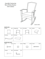
PARTS INVENTORY
Be sure to take a complete inventory of parts prior to beginning installation.
Description Qty Description Qty
Power Post 1 Parts Bag (Packaged in Part Box) 1
Front Post 1 Lifting Rod Assembly 4
Front Closeout Post 1 Long Angle 4
Rear Closeout Post 1 Short Angle 4
Top Ramp Weldment 1 Cable Break Safety Latch 4
Middle Ramp Weldment* 1
Bottom Ramp Weldment 1 Parts Box (Packing List Enclosed) 1
Rear Short Crosstube 1
Front Short Crosstube 1
Long Crosstube 1
Bottom Ramp
Weldment
Lifting Rod
Assembly
Top Ramp
Weldment
Middle Ramp
Weldment*
*Included with PL-18000 models only
Power
Post
Short
Angle
Long
Angle
Long
Crosstube
Rear Short
Crosstube
Front Short
Crosstube
Front Closeout
Post
Rear Closeout
Post
Cable Break
Safety Laatch
Front Post

9
FLOOR PLAN / GENERAL SPECIFICATIONS
PL-14000 GENERAL SPECIFICATIONS
Lifting Capacity 14,000 lbs / 6,350 Kg.
Max capacity / Top Ramp 7,000 lbs. / 3,175 kg
Max capacity / Top Ramp Front Axle 3,500 lbs. / 1,588 kg
Max capacity / Top Ramp Rear Axle 3,500 lbs. / 1,588 kg
Max capacity / Bottom Ramp 7,000 lbs. / 3,175 kg
Max capacity / Bottom Ramp Front Axle 3,500 lbs. / 1,588 kg
Max capacity / Bottom Ramp Rear Axle 3,500 lbs. / 1,588 kg
Ramp Locking Positions 2
Lock Spacing 80”/ 2032mm
Lifting Time 140 Seconds
Standard Motor (**) 220 VAC / 60Hz 1 Ph.
** Special Voltages Available upon Request.
The design, material and specications are subject to change without notice.
4797
2448
1921
2104
4590
4931
7121
2316
3883

10
FLOOR PLAN / GENERAL SPECIFICATIONS
5305
2448
2099
5098
1904
5439
7121
2317
4391
PL-14000XL GENERAL SPECIFICATIONS
Lifting Capacity 14,000 lbs / 6,350 Kg.
Max capacity / Top Ramp 7,000 lbs. / 3,175 kg
Max capacity / Top Ramp Front Axle 3,500 lbs. / 1,588 kg
Max capacity / Top Ramp Rear Axle 3,500 lbs. / 1,588 kg
Max capacity / Bottom Ramp 7,000 lbs. / 3,175 kg
Max capacity / Bottom Ramp Front Axle 3,500 lbs. / 1,588 kg
Max capacity / Bottom Ramp Rear Axle 3,500 lbs. / 1,588 kg
Ramp Locking Positions 2
Lock Spacing 80”/ 2032mm
Lifting Time 140 Seconds
Standard Motor (**) 220 VAC / 60Hz 1 Ph.
** Special Voltages Available upon Request.
The design, material and specications are subject to change without notice.

11
FLOOR PLAN / GENERAL SPECIFICATIONS
4797
4590
2484
1933
1954
1996
4931
9144
2313
3023
3883
PL-18000 GENERAL SPECIFICATIONS
Lifting Capacity 18,000 lbs / 8,164 Kg
Max capacity / Top Ramp 6,000 lbs / 2,721 kg
Max capacity / Top Ramp Front Axle 3,000 lbs / 1,360 kg
Max capacity / Top Ramp Rear Axle 3,000 lbs / 1,360 kg
Max capacity / Middle Ramp 6,000 lbs / 2,721 kg
Max capacity / Middle Ramp Front Axle 3,000 lbs / 1,360 kg
Max capacity / Middle Ramp Rear Axle 3,000 lbs / 1,360 kg
Max capacity / Bottom Ramp 6,000 lbs / 2,721 kg
Max capacity / Bottom Ramp Front Axle 3,000 lbs / 1,360 kg
Max capacity / Bottom Ramp Rear Axle 3,000 lbs / 1,360 kg
Ramp Locking Positions 3
Lock Spacing 80”/ 2032mm
Lifting Time 210 Seconds
Standard Motor (**) 220 VAC / 60Hz 1 Ph.
** Special Voltages Available upon Request.
The design, material and specications are subject to change without notice.

12
LIFT HEIGHT CLEARNACE NOTE: There must be a 3” MIN distance from the top of the parking lift to the near-
est obstruction or ceiling.
CLEARANCES
PL-14000/18000

13
STEP 3
(Closeout Side Post Installation)
1. Place a chalk lines on the floor according to the floor
plan layout. Be sure to take correct “Rear” clearance spacing
into consideration for the Hydraulic Power Unit. (See Fig 3.1)
2. Locate the Front and Rear Closeout Posts. Using a forklift
or crane lay them next to each other on the floor oriented so
that the base plates are on the same side and the Crosstube
Clevises are oriented inward. (See Fig 3.2)
NOTE: If sheaves were factory installed, it will be helpful to
remove the Cable Sheaves from each post prior to raising.
3. Using a forklift or crane, lift the Rear Closeout Post up-
right and place it into position on the “Rear - Closeout Side”
using the chalk lines that were marked earlier in this step.
DO NOT remove forklift or crane once post is upright. (See
Fig 3.3)
4. Using the baseplate as a guide, drill each anchor hole in
the concrete approximately 7” deep using a rotary hammer
drill and 3/4” concrete drill-bit. (See Fig 3.4)
5. After drilling the anchor holes, remove the dust thor-
oughly from each hole using compressed air and/or wire
brush.
6. Assemble the washers and nuts on the anchors then
tap into each hole with a hammer until the washer rests
against the base. Be sure that enough threads are left
exposed, if shimming is required. (See Fig. 3.5)
7. If shimming is required, insert the shims as necessary
around each anchor bolt. (See Fig. 3.6)
WARNING!
THIS STEP REQUIRES LIFTING OF VERY HEAVY
COMPONENTS. BE SURE TO USE THE CORRECT
LIFTING TOOLS SUCH AS FORKLIFTS OR CRANES
TO POSITION COMPONENTS. PAY ATTENTION TO
COMPONENTS POSITION ONCE COMPONENTS
ARE LIFTED. ONCE LIFTED, COMPONENTS
ARE FALLING HAZARDS. FAILURE TO USE THE
CORRECT LIFTING TOOLS OR TO PAY ATTENTION
DURING LIFTING MAY RESULT IN PERSONAL
INJURY OR DEATH. A MINIMUM OF A TWO PERSON
INSTALLATION TEAM IS RECOMMENDED FOR SAFE
LIFTING PRACTICES.
Fig 3.1
“Approach”
“Closeout
Side”
“Power Side”
“Rear”
Fig 3.3
7
Fig 3.4
Fig 3.5
Fig 3.2
Crosstube
Clevises
NOTE: Base
Plates are oriented
in same direction.

14
8. Using a three-foot level, make sure the Post is plumb.
9. With the shims and anchor bolts in place, and the post
determined to be level, tighten nut three to five turns past
finger tight. DO NOT use an impact wrench for this proce-
dure. (See Fig. 3.7)
10. The forklift or crane may now be removed.
11. Repeat Steps 3 - 10 for the Front Closeout Post.
12. Locate one of the Long Crosstubes and slide the
Crosstube Endplates in between the Crosstube Clevises
and align the thru holes. Make sure the Long Angle Bracket
faces towards the Base Plates. (See Fig. 3.8)
13. Install the supplied M18 bolts, washers, spring lock
washers, and nuts to securely fasten the Long Crosstube to
the Rear Closeout Post and Front Closeout Post. (See Fig.
3.9)
14. Place two Long Angles on to the Long Angle Brackets
of the Posts and the Crosstube and align the Long Angle
mounting holes with the Crosstube mounting holes and Post
mounting slots. (See Fig 3.10)
15. Install the supplied M18 bolts, spring lock washers, and
nuts to securely fasten the Long Angles to the Closeout Side
Posts and Long Crosstube. (See Fig. 3.11)
Fig 3.8
Long Angle
Bracket
Fig 3.10
Mounting
Brackets
Fig 3.9
M18 Nut
M18 Spring
Lock Washer
M18 Bolt
M18 Washer
Fig 3.11
M18 Nut
M18 Spring
Lock Washer
M18 Bolt
M18 Washer
Fig 3.6
NOTE:
THE MAXIMUM SHIM THICKNESS RECOMMENDED BY
THE FACTORY IS NO MORE THAN 1/2” PER COLUMN
USING SHIMS AND ANCHORS PROVIDED WITH THE
LIFT. A MAXIMUM SHIM THICKNESS OF 2” IS POSSIBLE
BY ORDERING OPTIONAL SHIM PLATES. CONTACT
YOUR AUTHORIZED BENDPAK DISTRIBUTOR FOR
ORDERING INFORMATION.
Fig 3.7

15
STEP 4
(Ramp Assembly)
NOTE: The PL-18000 model is depicted throughout
this step. Disregard any instruction regarding “Middle
Ramp” for PL-14000 installation.
1. Locate the Ramp Weldments. Using a forklift, lift the Top
Ramp Weldment and set the ramp down onto the Middle
Ramp Weldment and the Middle Ramp Weldment onto the
Bottom Ramp Weldment. It may be helpful to set the ramps
down on to wood blocks to help unload the ramps from the
forklift. Align the thru holes in the ramps as closely as pos-
sible. (See Fig 4.1)
2. Locate the Cable Break Safety Latches.
Align the mounting
holes of the Cable Break Safety Latches with the mount-
ing holes of the Top Ramp Weldment. Fasten the two com-
ponents together using the provided clevis pins, snap rings
and set screws. Repeat on all 4 corners. (See Fig 4.2)
3.
Locate the Lifting Rod Assemblies and disassemble the
Lifting Collars and the Cable Retainers. (See Fig
4.3)
4. Insert the Lifting Collar through the bottom of the Top
Ramp Weldment. Inset the Middle Lifting Collar through the
bottom of the Middle Ramp Weldment. (See Fig 4.4)
5. Take the Lifting Rod Assemblies that were disassem-
bled in Item 3 and align the rod and tubes with the thru holes
of the Cable Break Safety Assembly and the ramps. Ap-
ply loctite to the tube threads before assembling the collars.
Hold the Large Lifting Tube in place as the Lifting Collar is
threaded on. (See Fig 4.5)
Fig 4.2
Fig 4.1
Fig 4.3
Fig 4.4
Fig 4.5
Top Lifting
Collar
Lifting Collar
Middle
Lifting Collar
PL-14000
Lifting Rod
Assembly
PL-18000
Lifting Rod
Assembly
Cable
Retainer
Cable Break
Safety Latch
Set Screw
Clevis Pin
Snap Ring
Lifting Collar
Middle
Lifting Collar
Large Lifting
Tube
Middle
Lifting Tube
Cable Break
Safety Assembly
Lifting Collar
Middle
Lifting Collar
Lifting Rod

16
6. Attach the large and small Cable Break Safety Springs.
(See Fig 4.6)
7. When the Lifting Rod is through the Bottom Ramp
Weldment fasten a nylock nut and washer to the end of each
Lifting Rod. (See Fig 4.7)
9. Using a forklift, lift the Ramp Weldments and move them
so that the ends of the Ramp Weldments fit inside of the
posts. It may be helpful to set the ramps on wood blocks to
help unload the ramp from the forklift. (See Fig. 4.8)
STEP 5
(Power Side Post Installation)
1. Locate the Power Post, easily identified by the cylin-
der assembled in the post or the Sheave Pullbox mounted
inside of the post. Orient the Power Post so that the Sheave
Pullbox Glide Channel is easily accessible.
(See Fig. 5.1)
2. Inspect the ends of the Safety Spring inside the Sheave
Pullbox as shown. Make sure the spring ends are secure at
both ends. DO NOT ATTEMPT TO RAISE THE LIFT UNTIL
THE SAFETY SPRING IS ATTACHED AND THE ROLLER IS
PULLED TOWARDS THE SAFETY BAR BY THE SPRING.
(See Fig 5.2)
3. Locate the Safety Cable Connector, spacer and bolt in
the parts bag. Assemble them through the top hole of the
safety bar as shown in Figure 5.3.
4. Position the Power Post so that the post is laying on
its side with the cylinder side facing to the rear of the instal-
lation area. It may be helpful to position this post relatively
close to its final position to ease installation later. (See Fig.
5.4)
5. Position the Front Post so that the post is laying on its
side with the Control Box facing the Approach Side. It may
be helpful to position this post relatively close to its final posi-
tion to ease installation later. (See Fig. 5.5)
Fig 4.8
Fig 4.7
Bottom Ramp
Weldment
1-1/8” Washer
1-1/8” Nylock
Nut
Fig 5.1
Fig 5.2
Safety Bar
Roller
Safety Spring
Note: Cut-away view for clarification.
Fig 4.6
Large Cable
Break Safety
Spring
Small Cable Break
Safety Spring

17
6. Follow procedures of Step 3 (Closeout Side Post Instal-
lation) for the Power Side Posts then continue to the next
item. Remember to make sure ALL Cable Sheaves are re-
moved prior to raising Posts.
7. Locate the Front and Rear Short Crosstubes and slide
the Crosstube Endplates in between the Crosstube Clevises
and align the thru holes. Make sure the Short Angle Bracket
faces towards the Base Plates. (See Fig. 5.6-5.7)
8. Install the supplied M18 bolts, washers, spring lock
washers, and nuts to securely fasten the Short Crosstubes
to the Power Post and Front Post. (See Fig. 5.8)
Fig 5.4
Fig 5.5
Fig 5.6
Fig 5.3
M10 x 58mm Bolt
Spacer
Safety Cable
Connector
Note: Cut-away view for clarification.
Fig 5.7
Front Short
Crosstube
Rear Short
Crosstube
Front Post
Short Angle
Brackets
Fig 5.8
M18 Nut
M18 Spring
Lock Washer
M18 Bolt
M18 Washer

18
9. Place Short Angles on to the Short Angle Brackets
of the Posts and the Crosstube and align the Short Angle
mounting holes with the Crosstube mounting holes and Post
mounting slots. (See Fig 5.9)
NOTE: There are two Front Short Angles and two Longer
Rear Short Angles. Make sure that the Longer Short Angles
are installed at the REAR of the lift.
10. Install the supplied M18 bolts, spring lock washers, and
nuts to securely fasten the Short Angles to the Front Post,
Power Post, and Short Crosstubes. (See Fig. 5.10)
11. Make sure both ramp tabs are aligned inside both
posts. (See Fig 5.11)
14. Using a three-foot level, make sure the Power Side and
Front Posts are plumb.
15. Using the base of the frame as a guide, drill each anchor
hole and anchor the Power Side and Front Posts following
the procedures at the end of Step 3. Shim posts if necessary.
16. The forklift or crane may now be removed.
STEP 6
(Cable / Sheave Installation)
1. In order to install the cables, it is necessary to first
extend the Hydraulic Cylinder. Remove both cylinder port
plugs, then use an rubber tipped air gun or ratcheting pull-
strap to extend the cylinder. (See Fig 6.1)
2. Once cylinder is extended, attach cables by anchor-
ing the threaded end connectors through the Sheave Box
Bottom Plate along with the provided hardware. Use the
diagram to route the cables around the correct sheaves.
Route cables from outside of sheave to inside post.
(See Fig 6.2)
Fig 5.10
Fig 5.9
Rear Short
Angle
Front Short
Angle
Fig 5.11
M18 Nut
M18 Spring
Lock Washer
M18 Bolt
M18 Washer
Fig 6.1
Apply Air
Here
WARNING!
DO NOT EXCEED 50 PSI. IF CYLINDER DOES NOT MOVE
IMMEDIATELY STOP AND USE A COME-ALONG OR
OTHER PULLING DEVISE. KEEP HANDS CLEAR.
WARNING!
TAKE CARE TO NOT DAMAGE THE CHROME ROD
DURING THIS STEP. DAMAGING THE CHROME
ROD WILL VOID WARRANTY.
WARNING!
WHEN THE CABLE ADJUSTING NUTS BOTTOM
OUT ON THE THREADED END OF THE CABLE
CONNECTOR AND THERE IS STILL SLACK IN
THE CABLES, THE CABLES HAVE STRETCHED
BEYOND THE SAFE USEFUL LENGTH AND NEED
TO BE REPLACED WITH FACTORY APPROVED
CABLE ASSEMBLIES. DO NOT PLACE WASHERS,
SPACERS OR OTHER DEVICES TO “SHORTEN” THE
EFFECTIVE CABLE LENGTH AS DAMAGE TO THE
LIFT OR INJURY TO PERSONS MAY OCCUR.

19
3. Route the Cables around the sheaves as they are rein-
stalled. Insert 3 sheaves and 2 spacers into the bottom part
of the Power Post Sheave Box and secure the sheaves with
the Upper Sheave Stack Pin. Then insert 1 sheave and 2
spacers into the upper part of the Sheave Box and slide it
towards the interior of the lift. Secure the top sheave with
the Single Sheave Pin. Install the supplied M10 bolt and
nylock nut to securely fasten the pin.
(See Fig 6.3)
NOTE: Failure to install FRICTION SPACERS will result in prema-
ture sheave wear and void warranty.
4. To install the horizontally oriented sheave in the Front
Post Sheave Box tilt it at an angle as it is slid in and rotate
it once it is inside the Sheave Box. Then insert 2 sheave
spacers and install the Single Sheave Pin vertically and bolt
in place. Insert the lower sheave through the back of the
Sheave Box with 2 spacers and secure with Single Sheave
Pin and hardware. (See Fig 6.4-6.5)
5. In the Front Closeout Post insert a sheave and 2 spac-
ers into the lower part of the Sheave Box from the side of
the Sheave Box and secure with a Single Sheave Pin and
bolt in place. (See Fig 6.6)
6. In the Rear Closeout Post insert a sheave and 2 spac-
ers into the upper part of the Sheave Box from the outside
of the Sheave Box and slide it towards the interior of the lift.
Secure with a Single Sheave Pin and bolt in place. (See Fig
6.7)
NOTE:
THE CABLES ARE NAMED IN ORDER FROM THE
SHORTEST (A) TO THE LONGEST (D).
Fig 6.2
Cable “A”
Cable “B”
Cable “D”
Cable “C”
Sheave “A”
Sheave “C”
Sheave “D”
Sheave “B”
Sheave Box
Bottom Plate
Upper
Sheave
Stack Pin
Single
Sheave Pin
M10 Nylock
Nut
M10 Bolt
Fig 6.4
Fig 6.5
Fig 6.3
Washer
and Nylock
Nut

20
7. Once the Cables are anchored to the Power Post and
the sheaves are installed in the correct positions, route the
plug end of each cable through the hole in the bottom plate
of each Sheave Box. Refer to the Lifting Cable Routing
Diagram on the following pages.
Fig 6.6
Fig 6.7
/