

Your Local Agent/DealerYour Local Agent/Dealer
9-52 Ashihara-cho,9-52 Ashihara-cho,
Nishinomi
y
a, Ja
p
anNishinomi
y
a, Ja
p
an
Tele
p
hone :Tele
p
hone : 0798-65-21110798-65-2111
Telefax :Telefax : 0798-65-42000798-65-4200
FIRST EDITION :FIRST EDITION : SEP.SEP. 19951995
Printed in JapanPrinted in Japan
A
ll ri
g
hts reserved.
A
ll ri
g
hts reserved. U :U : JUN.JUN. 03,200203,2002
PUB.No.PUB.No. OME-43740OME-43740
*00080733901**00080733901*
*00080733901**00080733901*
(( DAMIDAMI )) GP-80GP-80 * 0 0 0 8 0 7 3 3 9 0 1 ** 0 0 0 8 0 7 3 3 9 0 1 *
*OME43740U00**OME43740U00*
*OME43740U00**OME43740U00*
* O M E 4 3 7 4 0 U 0 0 ** O M E 4 3 7 4 0 U 0 0 *

iiiiiiiiiiiii i
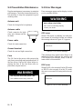
"DANGER", "WARNING" and "CAUTION" notices appear throughout this manual. It is the
responsibility of the operator and installer of the equipment to read, understand and follow
these notices. If you have any questions regarding these safety instructions, please con-
tact a FURUNO agent or dealer.
DANGER
This notice indicates a potentially
hazardous situation which, if not
avoided, will result in death or
serious injury.
This notice indicates a potentially
hazardous situation which, if not
avoided, could result in death or
serious injury.
This notice indicates a potentially
hazardous situation which, if not
avoided, could result in minor or
moderate injury, or property damage.
CAUTION
WARNING
SAFETY INSTRUCTIONS

ii
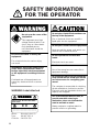
SAFETY INFORMATION
FOR THE OPERATOR
WARNING Label attached
Name : Warning Label (1)
Type : 86-003-1011-0
Code No. : 100-236-230
WARNING
To avoid electrical shock, do not
remove cover. No user-serviceable
parts inside.
- -
- - - - - - - - - - - - - - - - - - - - - - - - - - - - -
- - - - - - - - - - - - - - - - - - - - - - - - - - - - -
- - - - - - - - - - - - - - - - - - - - - - - - - - - - -
Do not open the cover of the
equipment.
This equipment uses high
voltage electricity which can
shock, burn or cause death.
Only qualified person-
nel should work inside the
equipment.
WARNING
Do not dissasemble or modify the
equipment.
Fire, electrical shock or serious injury
can result.
Immediately turn off the power at the
ship's mains switchboard if water or
foreign object falls into the equipment
or the equipment is emitting smoke or
fire.
Continued use of the equipment can
cause fire, electrical shock or serious
injury.
CAUTION
Do not place liquid-filled containers on
the top of the equipment.
Fire or electrical shock can result if a
liquid spills into the equipmtnt.
Do not place heater neat the equipment.
Heat can melt the power cord, which can
result in fire or electrical shock.
Do not operate the unit with wet
hands.
Electrical shock can result.
Use the correct fuse.
Use of the wrong fuse can cause fire or
equipment damage.
No single navigation aid (including this
unit) should ever be relied upon as the
exclusive means for navigating your
vessel.
The navigator is responsible for checking
all aids available to confirm his position.
Electronic aids are intended to assist, not
replace, the navigator.
Use of an autopilot with this unit, to
provide automatic steering to
destination, does not eliminate the
need to maintain a watch.
Always maintains a vigilant watch to
prevent collision or grounding.

iii
TABLE OF
CONTENTS
FOREWORD............................iii
SYSTEM OVERVIEW ...............1
1. OPERATIONAL OVERVIEW
1.1 Control Description .......................... 1-1
1.2 Turning On and Off the Power ......... 1-2
1.3 Adjusting Display Contrast and
Brilliance .......................................... 1-3
1.4 Selecting the Display Mode.............. 1-3
1.5 Chart Icons........................................ 1-6
2. TRACK5
2.1 Enlarging/Shrinking the Display ...... 2-1
2.2 Selecting Display Orientation........... 2-1
2.3 Shifting the Cursor............................ 2-1
2.4 Shifting the Display .......................... 2-2
2.5 Centering Cursor Position.................2-3
2.6 Centering Own Ship's Position .........2-3
2.7 Stopping/Starting Plotting and
Recording of Track ........................... 2-3
2.8 Erasing Track.................................... 2-4
2.9 Selecting Track Plotting Interval ...... 2-4
2.10 Apportioning the Memory .............. 2-5
2.11 Selecting Bearing Reference........... 2-6
3. MARKS
3.1 Entering/Erasing Marks .................... 3-1
3.2 Selecting Mark Shape....................... 3-2
3.3 Connecting Marks (selecting mark
connection line) ................................ 3-2
3.4 Entering Event Marks....................... 3-3
3.5 Selecting Event Mark Shape............. 3-3
3.6 Entering the MOB Mark................... 3-4
4. NAVIGATION PLANNING
4.1 Registering Waypoints ...................... 4-1
4.2 Editing Waypoints............................. 4-4
4.3 Deleting Waypoints........................... 4-5
4.4 Registering Routes............................ 4-5
4.5 Deleting Route Waypoints................ 4-6
4.6 Replacing Route Waypoints.............. 4-7
4.7 Deleting Routes ................................ 4-7
5. STARTING FOR
DESTINATION
5.1 Setting Destination ........................... 5-1
5.2 Cancelling Destination...................... 5-5
5.3 Erasing Route Waypoints (flags) ...... 5-6
5.4 Finding Range and Bearing Between
Two Points ........................................ 5-7
6. SETTING UP VARIOUS
DISPLAYS
6.1 Selecting Data to Display on the
Data Display ..................................... 6-1
6.2 Selecting Position Format................. 6-2
6.3 Demo Display ................................... 6-4
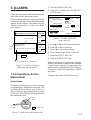
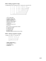
7. ALARMS
7.1 Arrival Alarm, Anchor Watch
Alarm ................................................ 7-1
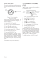
7.2 Cross Track Error (XTE) Alarm ....... 7-2
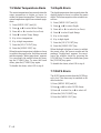
7.3 Ship’s Speed Alarm .......................... 7-3
7.4 Trip Alarm......................................... 7-3
7.5 Water Temperature Alarm................. 7-4
7.6 Depth Alarm ..................................... 7-4
7.7 DGPS Alarm ..................................... 7-4
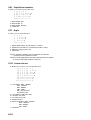
8. MENU SETTINGS
8.1 GPS Menu......................................... 8-1
8.2 Selecting Units of Measurement....... 8-3
8.3 Mark, Character Size and
Brilliance .......................................... 8-4
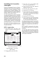
8.4 Settings for Connection of
Navigator .......................................... 8-6

iv
8.5 Receiving Data from Personal
Computer .......................................... 8-8
8.6 DGPS Settings ................................ 8-10
8.7 Displaying GPS Monitor Displays . 8-12
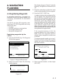
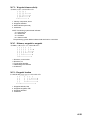
9. MAINTENANCE &
TROUBLESHOOTING
9.1 Clearing the Memory........................ 9-1
9.2 Preventative Maintenance................. 9-2
9.3 Error Messages ................................. 9-2
9.4 Troubleshooting ................................ 9-4
9.5 Self Tests........................................... 9-5
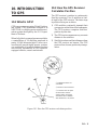
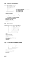
10. INTRODUCTION TO GPS
10.1 What is GPS?................................ 10-1
10.2 How the GPS Receiver
Calculates Position........................ 10-1
10.3 Position-fixing Accuracy
(HDOP)......................................... 10-2
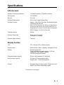
APPENDIX
Specifications......................................... A-1
Digital Interface ..................................... A-3
Time Differences ................................. A-17
Geodetic Chart List.............................. A-18
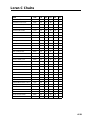
Loran C Chains.................................... A-19
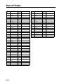
Decca Chains ....................................... A-20
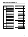
DGPS Reference Station List .............. A-21
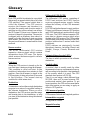
Glossary ............................................... A-24
INDEX............................................. Index-1
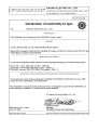
Declaration of conformity to type

v
FOREWORD
A Word to GP-80 Owners
Congratulations on your choice of the
FURUNO GP-80 GPS Navigator. We are con-
fident you will see why the FURUNO name
has become synonymous with quality and re-
liability.
For over 40 years FURUNO Electric Com-
pany has enjoyed an enviable reputation for
innovative and dependable marine electron-
ics equipment. This dedication to excellence
is furthered by our extensive global network
of agents and dealers.
Your navigator is designed and constructed
to meet the rigorous demands of the marine
environment. However, no machine can per-
form its intended function unless operated and
maintained properly. Please carefully read and
follow the recommended procedures for op-
eration and maintenance.
We would appreciate hearing from you, the
end-user, about whether we are achieving our
purposes.
Thank you for considering and purchasing
FURUNO equipment.
Features
The GP-80 GPS Navigator is a totally inte-
grated GPS receiver and video plotter con-
sisting of a display unit and an antenna unit.
The high sensitivity receiver tracks up to eight
satellites simultaneously. An 8-state Kalman
filter ensure optimum accuracy in determina-
tion of vessel position, course and speed.
In most cases the operator need do no more
than turn on the power to find position.
The main features of the GP-80 are
• Comprehensive navigation data displays
• Storage for 999 waypoints and 30 routes
• Alarms: Arrival, Anchor Watch, Cross-
track Error, Ship's Speed, Water Tempera-
ture, Depth, and Trip
• Man overboard feature records latitude and
longitude coordinates at time of man over-
board and provides continuous updates of
range and bearing to that point
• DGPS capability—with built-in DGPS
beacon kit, or accepts DGPS correction
data from external DGPS beacon receiver
• Menu-driven operation
• Bright 122 x 92 mm LCD with tempera-
ture compensated tone and brilliance ad-
justment
• Power consumption is a low 10 W.
• Provision for connection of autopilot (op-
tion)—steering data output to autopilot
• Digital display of water temperature and
depth with connection of video sounder
(with NMEA input)
• Memory stores 2,000 points of track and
marks
• "Highway" display provides perspective
view
• Position may be shown in latitude and lon-
gitude or LOP (Loran or Decca)
• Four connectors for optional equipment
two IEC 61162-1/NMEA 0183 I/O, one
IEC 61162-1/NMEA 0183 (or log) output
and one DGPS for personal computer) I/O
Program No.
2051011-017 (Apr. 2002)

This page is intentionally left blank.

1
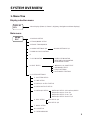
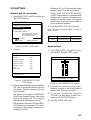
DISPLAY
SEL Select Display (Plotter 1, Plotter 2, Highway, Navigation and Data displays)
Display selection menu
Main menu
MENU
ESC 1. DISPLAY SETUP
2. TRACK/MARK SETUP
3. ERASE TRACK/MARK
4. ALARM SETTINGS 1/2 ALARM SETTINGS 2/2
5. MANUAL CALCULATION
6.
7. GPS MONITOR SATELLITE MONITOR
BEACON RCVR MONITOR
STATION MESSAGE
8. SELF TESTS 1. MEMORY, I/O PORT TEST
2. KEYBOARD TEST
3. TEST PATTERN
4. AUTOMATIC TESTING
1. PLOTTER SETUP
2. UNIT SETUP
4. DATA2 OUTPUT SETUP
5. DATA4 I/O SETUP
6. GPS SETUP
9. SYSTEM SETTINGS
DATA4 I/O SETUP "Out" 2/2
DATA4 I/O SETUP "Com." 2/2
GPS SETUP 2/2
7. DGPS SETUP
8. LOP SETUP
9. CLEAR MEMORY
3. DATA1, 3 OUTPUT SETUP
DATA4 I/O SETUP "DGPS" 2/2
GPS SETUP 1/2
DATA4 I/O SETUP 1/2 Out/Com./DGPS
SYSTEM OVERVIEW
1. Menu Tree

2
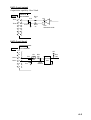
Waypoint, route menu
WPT
RTE
1. Cursor
2. MOB/Event Position
3. Own Ship Position
4. Waypoint List WAYPOINT LIST
5. Route Planning ROUTE LIST
GOTO menu
GOTO
1. Cursor
2. MOB/Event Position
3. Waypoint List GOTO "Waypoint List"
5. Cancel
4. Route List GOTO "Route List"

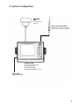
3
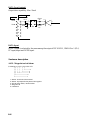
2. System Configuration
ANTENNA
UNIT
Receives GPS
signals.
DISPLAY UNIT
Receives and processes
GPS signals to fix
position and display
it in latitude/longitude or LOP.
BEACON ANTENNA UNIT
Receives GPS correction data
from DGPS reference station.
Ship's Mains
10.2 to 31.2 VDC

4
• Plotter 1 (own ship's track and data)
• Plotter 2 (own ship's track)
• Highway (ship's track overlaid on
navigation lane)
• Navigation (graphic navigation data
display for steering)
• Data (alphanumeric navigation data)
Select display
mode
Set destination temporarily
Set
destination
Display steering data
• By latitude and longitude
• By LOP
Register
waypoints
Register
routes
Set alarms
Perform other operations as required.
(Position correction, geodetic chart to use,
enter smoothing, calculate range and
bearing to a point, etc.)
3. Operation Flow Chart

1–1
1. OPERATIONAL
OVERVIEW
1.1 Control Description
Figure 1-1 Control panel
Cursor keys
Shift display and
cursor.
Adjusts display contrast;
changes latitude/longitude
coordinate.
Turns power on/off.
Sets destination.
Deletes waypoints and marks;
clears wrong data; silences
audible alarm.
Expands display
range.
Selects display orientation;
registers selections on menus.
Turns recording and plotting
of ship's track on/off.
Inscribes mark on
the display.
MENU
ESC NU/CU
ENT
EVENT
MOB
WPT
RTE GOTO
MARK PLOT
ON/OFF
ZOOM
OUT
CENTER CURSOR
ON/OFF
TONE CLEAR
Inscribes event mark at
ship's position; marks man
overboard position
Decreases display range.
Turns cursor on/off.
Centers ship's position/cursor
position.
Registers waypoints
and routes.
Selects display mode.
Opens/closes menu;
quits current operation.
DISPLAY
SEL
ZOOM
IN
1
2
3
4
50
9
8
7
6
POWER

1–2
1.2 Turning On and Off the
Power
The GP-80 takes about two minutes to find
position when turned on for the very first time.
Thereafter it takes about 20 seconds to find
position each time the power is turned on.
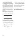
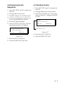
Turning on the power
Press the [POWER] key.
The unit tests the PROGRAM MEMORY,
SRAM and battery for proper operation and
shows the results on the display. If equipped
with the internal beacon receiver, "BEACON
RCVR INSTALLED" appears at the bottom
of the display. The unit starts up with the last
used display mode.
*: This indication is only when beacon re-
ceiver is installed.
Figure 1-2 Appearnace of display when
turning on the power
When turning on the power the following oc-
curs:
20 seconds after turning on the power, accu-
rate position (in latitude and longitude) ap-
pears on the display.
When turning on the power the following oc-
curs:
20 seconds after turning on the power, accu-
rate position (in latitude and longitude) ap-
pears on the display.
If position could not be found, "NO FIX" ap-
pears at the GPS receiver condition window.
When PDOP value exceeds 6 in the 3D mode
or HDOP value exceeds 4 in the 2D mode,
"DOP" appears to indicate abnormal fixing
and the position indication could not be up-
dated.
When the satellite signal is being received nor-
mally, one of the indications shown in Table
1-1 appears depending on equipment setting
and GPS receiver state.
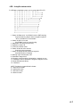
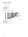
Table 1-1 GPS receiver indication
PROGRAM MEMORY = OK
SRAM = OK
Internal Battery = OK
---°
7°
GPS 3D
34° 23.456´ N 135° 45.678´ E
BRG
RNG
123
12.3
SPD
kt
CSE
[01]
30
40
20
50
H
2nm
BEACON RCVR INSTALLED*
DATA #3 : LOG PULSE OUTPUT
GPS receiving
condition
Several seconds
later
A
WGS84
nm
tnempiuqE gnittes etatsreviecerSPG noitacidni
D2)lamron(D2SPG
D3)lamron(D3SPG
laitnereffiD
D2 )lamron(D2SPGD
laitnereffiD
D3 )lamron(D3SPGD
Figure 1-2 Appearnace of display when
turning on the power

1–3
Note 1: When PDOP value exceeds 6 in the
3D mode, the position fixing method is
automatically changed to 2D.
Note 2: The "DEMO" icon appears when the
display is in the demonstration mode. To return
to normal mode, turn off the power and turn it
on while pressing and holding down the [NU/
CU ENT] key.
Note 3: Refer to page 10-2 about HDOP and
PDOP.
Turning the power off
Press the [POWER] key.
The next time you turn on the power the unit
starts up with the last used display mode.
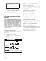
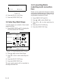
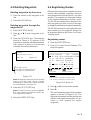
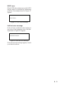
1.3 Adjusting Display
Contrast and Brilliance
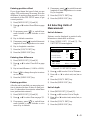
1) Press the [TONE] key. The display shown
in Figure 1-3 appears.
Figure 1-3 Screen for adjustment of display
contrast and brilliance
2) To adjust contrast, press t or s. Cur-
rent setting and setting range (0–31) are
shown to the right of "s".
3) To adjust brilliance, press ▲ or ▼. Cur-
rent setting and setting range (0–4) are
shown to the right of "▲".
Note: Operate cursor keys within 10 seconds
after pressing the [TONE] key. Otherwise, the
screen for adjustment of contrast and brilliance
will be cleared.
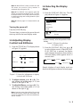
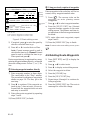
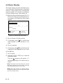
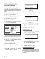
1.4 Selecting the Display
Mode
1) Press the [DISPLAY SEL] key. The dis-
play shown in Figure 1-4 appears.
* Shows currently selected geodetic chart
datum.
Figure 1-4 Screen for selection
of display mode
2) Press the [DISPLAY SEL] key, ▲ or ▼
to select display mode. (When the [DIS-
PLAY SEL] key is pressed, the display
mode changes in sequence shown below.)
Selected display mode appears about 15
seconds later.
Sample displays of each display mode are
shown in the figures on the next several pages.
Plotter 1 Plotter 2 Highway
Navigation
Data
Tone:
Brilliance:
[–] [+]
MENU : Escape
8 (0~31)
4 (0~4)
Plotter 1
Plotter 2
Highway
Navigation
Data
Select Display
Plotter 1
MENU : Escape
: Select
(DATUM: WGS-84)*

1–4
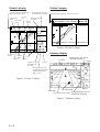
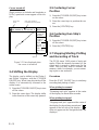
Plotter 1 display
Figure 1-5 Plotter 1 display
44°
DGPS 3D
34° 23.456´ N 135° 45.678´ E
BRG
32°
BRG TO +
11.5
RNG TO +
nm
123°
CSE
[01]
30
40
20
50
H
2.00 nm
Cursor position or lighthouse
data, when cursor is on
Own ship's
track Own ship
mark
Course
bar
Bearing from own ship
to destination waypoint
GPS receiving
condition
Alarm
range
Range from own ship
to destination waypoint,
or bearing from own
ship to cursor
Course
Grid
Cursor
Speed, or range
from own ship
to cursor
Course
width
Course
Horizontal
range
WGS84
Plotter 2 display
Figure 1-6 Plotter 2 display
Highway display
Figure 1-7 Highway display
[01]
30
40
20
50
H
2.00 nm
Ship's position appears when cursor is off
DGPS 3D
34° 23.456´ N 135° 45.678´ E
WGS84
Course
Bearing from own ship to
detination waypoint
Position
Speed
Range from own ship to
destination waypoint
Own ship mark
Cross track error scale
North mak
WGS84

1–5
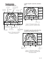
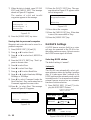
Navigation display
1) No autopilot connection
Figure 1-9 Navigation display,
no autopilot connection
2) With autopilot connection, automatic
mode
Figure 1-9 Navigation display, with
autopilot connection, automatic mode
3) Autopilot connection, modes other than
automatic mode (manual, nav, etc.)
Figure 1-10 Navigation display, with
autopilot connection, modes other than
the automatic mode
E
N
S
12.3
DGPS 3D
SPD
10.3
123
RNG
789
TRIP
nm
kt
VTD
kt
nm
BRG:
Auto
123°
TO;
012
0.1nm 0.1nm
63°
123°
CSE:
Auto Pilot Hdg
Auto mode
P 23°
Str
Heading
Rudder angleRudder angle
E
N
S
12.3
DGPS 3D
SPD
10.3
123°
AP CSE
789
TRIP
nm
kt
VTD
kt
BRG:
Man
123°
TO;
- - -
0.1nm 0.1nm
63°
123°
CSE:
Auto Pilot Hdg
P 23°
Str
Autopilot-set
course
Man: Manual mode
Nav: Nav mode
Other:---
Heading Rudder angle
E
3D
N
S
12.3
DGPS 3D
SPD
10.3
123
RNG
789
TRIP
nm
kt
VTD
kt
nm
BRG
23:45'
17H 45M
TO;
012
0.1nm 0.1nm
15
63°
123°
CSE
ETA TTG
Bearing from own
ship to destination
waypoint
Time To Go
(3days17hrs45min)
Cross track
error scale
Cross track
error indication
Cross track
error meter
Destination
waypoint no. Speed
Bearing
scale Velocity To
Destination
Range from own
ship to destination
waypoint
Trip
distance
Estimated Time of
Arrival (15th23:45)

1–6
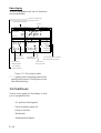
Data display
(Window assignment and size of characters
are user-definable)
Figure 1-11 Data display mode
*:"- -" appears until calculating position after
turning on the power. If fixing error occurs
this indication stops.
1.5 Chart Icons
Various icons appear on the display to alert
you to equipment status.
: L/L position offset applied.
: Track recording tunned off.
: Alarm is violated.
: North mark.
: Demonstration display.
SEP 12, 1995 23:59'59" U DGPS 3D
12° 23.456' N
123° 23.456' E
POSITION
RNG
31.23 nm
SPD
12.3 kt
BRG
223.4°
CSE
123.4°
TO : 001
MARINE
POINT1
NEXT : 002
MARINE
POINT2
Position in latitude and
longitude or LOPs
Fixing date and time* Cursor
User-defined
display window
User-defined
display data #1 User-defined
display data #4
User-defined
display data #3
User-defined
display data #2
Current destination waypoint
Next destination waypoint
WGS84

2–1
2. TRACK
2.1 Enlarging/Shrinking the
Display
You may enlarge and shrink the display on
the Plotter 1 and Plotter 2 displays, with the
[ZOOM IN] and [ZOOM OUT] keys. The
horizontal range is available among 0.25, 0.5,
1, 2, 4, 8, 16, 32, 64, 128 and 192 nautical
miles for plotter 1 and 0.36, 0.71, 1.42, 2.84,
5.69, 11.38, 22.76, 45.51, 91.02, 182.04,
273.07 nautical miles for plotter 2 display.
The [ZOOM IN] key enlarges the display and
the [ZOOM OUT] key shrinks it. Each time a
zoom key is pressed the display range appears
at the center of the display for about three sec-
onds.
2.2 Selecting Display
Orientation
Display orientation can be selected on the
Plotter 1, Plotter 2 and Highway displays, with
the [NU/CU ENT] key. Two display orienta-
tions are available: north-up and course-up.
North-up display
In the north-up display, true north (0 ) is at
the top of the display. Own ship moves on the
display in accordance with true speed and true
motion. Land is stationary.
Course-up display
Destination set
The destination is at the top of the display and
the north mark ( ) appears at the left side of
the display.
Destination not set
Ship's heading or course is at the top of the
display. The north mark appears at the left side
of the display.
2.3 Shifting the Cursor
The cursor can be shifted with the cursor keys.
1) Press the [CURSOR ON/OFF] key to turn
on the cursor.
2) Press the cursor keys.
The cursor moves in the direction of the cur-
sor key pressed. When the cursor reaches the
edge of the display, the display shifts in the
direction opposite.
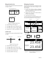
Data and cursor state
Cursor state determines what data are shown
on the display.
Cursor turned on, cursor data
Cursor position is displayed in latitude and
longitude or LOPs (depending on menu set-
ting) at the top of the display. The range and
bearing from own ship to the cursor appear at
the right hand side of the display, when in the
Plotter 1 display.
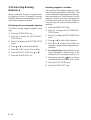
Cursor turned off
234°
BRG
345°
BRG To +
123°
11.5
RNG To +
nm
CSE
2.0 nm
Cursor mark Cursor position in
latitude and longitude
Cursor Range from own
ship to cursor
Bearing from own
ship to cursor
Figure 2-1 Data displayed when
the cursor in on
DGPS 3D
34° 23.456´ N 135° 45.678´ E
WGS84

2–2
Cursor turned off
Ship's position (in latitude and longitude or
LOPs), speed and course appear on the dis-
play.
Figure 2-2 Data displayed when
the cursor is turned off
2.4 Shifting the Display
The display can be shifted on the Plotter 1
and Plotter 2 displays, with the [CURSOR
ON/OFF] key. When own ship tracks off the
display it is automatically returned to the
screen center.
1) Press the [CURSOR ON/OFF] key to turn
off the cursor.
2) Press the cursor keys. The display shifts
in the direction of the cursor key pressed.
2.5 Centering Cursor
Position
1) Press the [CURSOR ON/OFF] key to turn
on the cursor.
2) Press the cursor keys to position the cur-
sor.
3) Press the [CENTER] key.
2.6 Centering Own Ship's
Position
1) Press the [CURSOR ON/OFF] key to turn
off the cursor.
2) Press the [CENTER] key.
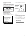
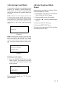
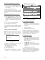
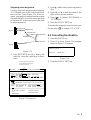
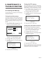
2.7 Stopping/Starting Plotting
and Recording of Track
The GP-80 stores 2,000 points of track and
marks. When the memory becomes full the
oldest track is erased to make room for the
latest. Thus you may want to conserve the
memory when, for example, you are return-
ing to port or are anchored.
Procedure
Press the [PLOT ON/OFF] key to start/stop
recording and plotting of track.
When plotting is resumed
"Resuming track plot" appears at the center
of the display for about three seconds.
When plotting is stopped
"Stopping track plot" appears at the center of
the display for about three seconds and "
H
"
appears at the left side of the display. ("
H
"
does not appear on the Navigation and Data
displays.)
234°
DGPS 3D
34° 23.456´ N 135° 45.678´ E
BRG
345°
RNG
123
12.3
SPD
nm
kt
CSE
Own ship
mark Own ship position
in latitude and longitude
Course
Speed
Page is loading ...
Page is loading ...
Page is loading ...
Page is loading ...
Page is loading ...
Page is loading ...
Page is loading ...
Page is loading ...
Page is loading ...
Page is loading ...
Page is loading ...
Page is loading ...
Page is loading ...
Page is loading ...
Page is loading ...
Page is loading ...
Page is loading ...
Page is loading ...
Page is loading ...
Page is loading ...
Page is loading ...
Page is loading ...
Page is loading ...
Page is loading ...
Page is loading ...
Page is loading ...
Page is loading ...
Page is loading ...
Page is loading ...
Page is loading ...
Page is loading ...
Page is loading ...
Page is loading ...
Page is loading ...
Page is loading ...
Page is loading ...
Page is loading ...
Page is loading ...
Page is loading ...
Page is loading ...
Page is loading ...
Page is loading ...
Page is loading ...
Page is loading ...
Page is loading ...
Page is loading ...
Page is loading ...
Page is loading ...
Page is loading ...
Page is loading ...
Page is loading ...
Page is loading ...
Page is loading ...
Page is loading ...
Page is loading ...
Page is loading ...
Page is loading ...
Page is loading ...
Page is loading ...
Page is loading ...
Page is loading ...
Page is loading ...
Page is loading ...
Page is loading ...
Page is loading ...
Page is loading ...
Page is loading ...
Page is loading ...
Page is loading ...
Page is loading ...
Page is loading ...
Page is loading ...
Page is loading ...
Page is loading ...
Page is loading ...
Page is loading ...
Page is loading ...
Page is loading ...
Page is loading ...
Page is loading ...
Page is loading ...
-
 1
1
-
 2
2
-
 3
3
-
 4
4
-
 5
5
-
 6
6
-
 7
7
-
 8
8
-
 9
9
-
 10
10
-
 11
11
-
 12
12
-
 13
13
-
 14
14
-
 15
15
-
 16
16
-
 17
17
-
 18
18
-
 19
19
-
 20
20
-
 21
21
-
 22
22
-
 23
23
-
 24
24
-
 25
25
-
 26
26
-
 27
27
-
 28
28
-
 29
29
-
 30
30
-
 31
31
-
 32
32
-
 33
33
-
 34
34
-
 35
35
-
 36
36
-
 37
37
-
 38
38
-
 39
39
-
 40
40
-
 41
41
-
 42
42
-
 43
43
-
 44
44
-
 45
45
-
 46
46
-
 47
47
-
 48
48
-
 49
49
-
 50
50
-
 51
51
-
 52
52
-
 53
53
-
 54
54
-
 55
55
-
 56
56
-
 57
57
-
 58
58
-
 59
59
-
 60
60
-
 61
61
-
 62
62
-
 63
63
-
 64
64
-
 65
65
-
 66
66
-
 67
67
-
 68
68
-
 69
69
-
 70
70
-
 71
71
-
 72
72
-
 73
73
-
 74
74
-
 75
75
-
 76
76
-
 77
77
-
 78
78
-
 79
79
-
 80
80
-
 81
81
-
 82
82
-
 83
83
-
 84
84
-
 85
85
-
 86
86
-
 87
87
-
 88
88
-
 89
89
-
 90
90
-
 91
91
-
 92
92
-
 93
93
-
 94
94
-
 95
95
-
 96
96
-
 97
97
-
 98
98
-
 99
99
-
 100
100
-
 101
101


Ask a question and I''ll find the answer in the document
Finding information in a document is now easier with AI
Related papers
-
Furuno GP-80 User manual
-
-
-
-
-
-
-
-
-
Other documents
-
Samyung SPR/DSPR-1400 Owner's manual
-
Si-tex HG7 User manual
-
Leica MK9 Technical Manual
-
Raymarine Raynav 300 Owner's Handbook Manual
-
 Seiwa Seahorse Series Owner's manual
-
JRC JMA-5300Mk2 PROLINE Owner's manual
-
-
-
-
Artsound Lighthouse Owner's manual
