Page is loading ...

Dalis Pro
Models
200DHWI5 / 260DHWI5 / 200DHW5 / 260DHW5
INSTRUCTIONS MANUAL
Information, operation & information
EN

2
IMPORTANT: When using electrical appliances, precautions should be taken to reduce
the risk of fire, electrical shock and injury to persons.
IMPORTANT: It is important the tundish is positioned away from any electrical components.
It should terminate in a safe place where there is no risk to persons in the vicinity of the
discharge. The discharge will consist of scalding water and steam. Asphalt, roofing felt
and non-metallic rainwater goods may be damaged by such discharges.
IMPORTANT: To disconnect the product from the main power supply, remove the plug
from the socket. Do not pull the cable.
WARNING: If the power cable is damaged, it must be replaced by ROINTE or its authorized
personnel in order to avoid any damage.
WARNING: Do not switch on the elecricity supply until instructed to do so in the
commissioning procedure and once the product is full of water.
WARNING: Servicing and product repairs should only be undertaken by ROINTE or its
authorized personnel using only exact manufacturer-approved spare parts.
WARNING: The product is IPX4 rated and must never be installed where itself or the
switches/control panel is within the reach of persons in water. Never use the product with
wet hands. Do not place any water containers (glasses, vases etc.) on or near the product.
WARNING: To avoid overheating do not cover the product. This includes furniture, curtains,
clothes and any other items. Do not insert any kind of object in the product. Obstructions
should not be placed in front, above or directly next to the product. Do not use insecticides,
paints, chemicals or aerosols on or near the product. Do not sit on the product. Failure to
comply with the above will render your guarantee invalid.
WARNING: This product can be used by children aged over 8 years
and by persons with reduced physical, sensory or mental capabilities, or
lack of experience and knowledge if they have been given supervision or
instruction concerning use of the product in a safe way and understand
the hazards involved. Children should not plug in, regulate, clean, play
with or perform maintenance on this product. Children aged less than 3
years should be kept away from the product unless supervised.
WARNING: If the cylinder is not being installed immediately, it should remain in its original
box with all pipe end protective caps in situ to prevent damage. We recommend that the
cylinder be transported to its installation position with the outer box in place.
WARNING: This product must be installed using a Rointe Installation Kit (sold separately).

3
DALIS PRO DOMESTIC HOT WATER HEAT PUMP
EN
CONTENTS
1. Introduction ................................................................................................................... 3
2. Disclaimer ..................................................................................................................... 4
3. Regulations ................................................................................................................... 4
4.
Principal function .......................................................................................................... 5
5. Mandatory installation kits ........................................................................................... 6
6. Safety information and warnings .................................................................................. 6
7. Technical information .................................................................................................... 8
8. Before installation ....................................................................................................... 12
9. Installation ................................................................................................................... 18
10.
Controller adjustment/Parameters ............................................................................. 27
11. External connectivity .................................................................................................. 30
12. Filling, start up and operation of the product ............................................................. 36
13. Functions .................................................................................................................... 40
14.
Troubleshooting .......................................................................................................... 41
15. Maintenance and cleaning .......................................................................................... 44
16. Product disposal ......................................................................................................... 46
17. Product guarantee ...................................................................................................... 46
18. Commissioning record ............................................................................................... 50
19. Service record ............................................................................................................ 51
1. INTRODUCTION
Thanks for choosing the Rointe Dalis heat pump, designed to produce sanitary domestic
hot water, through the use of heat pump technology. A liquid / refrigerant gas flows inside
this product.
This model consists of a compressor, evaporator, condenser and a throttle valve.
The product is manufactured from high quality components and meets all health and safe-
ty requirements. Before installing and / or using this product, carefully read this manual.
This manual must be kept with the product at all times, even if the ownership of the product
changes.
If you have any questions, please contact our Technical Support department by phoning
0203 321 5929 or send an email to suppor[email protected].uk.

4
IMPORTANT
This product has been manufactured for domestic hot water as part of a pressurised water heating
system. Rointe will not take responsibility for safe operation of this product outside of the scope
of intended use.
Please read this manual carefully, including all warnings and important information.
2. DISCLAIMER
This manual has been thoroughly verified, however in some instances non-compliance can
occur. Therefore we (Rointe) accept no liability for complete conformity.
We reserve the right to carry out modifications to the product’s construction, character-
istics or its data at any time. Therefore, we do not accept any liability claims attributable
to instructions, figures, drawings or descriptions, without prejudice to errors of any kind.
We will not be held responsible for damages attributable to incorrect installation, product
misuse or improper use, or as a consequence of unauthorised repairs, modifications or
replacement.
3. REGULATIONS
The equipment can only be installed and commissioned for use within domestic water
closed heating systems, according to the BS EN 12828 standard. It adheres to the following
directives:
• Directive 2011/65/UE on use of hazardous substances in electronic equipment (RoHS).
• Directive 2014/30/UE Electromagnetic compatibility (EMC).
• Directive 2014/35/EU Low Voltage Directive (LVD).
• Directive 2009/125/CE Ecodesign requirements.
• Directive 2010/30/UE Energy labelling.
• Directive 2012/19/UE on waste electrical and electronic equipment (WEEE).
3.1. Protection degree
The product has a Protection Degree of IPX4.
3.2. Refrigerant/coolant used
The type of refrigerant used is: HFC-R134a. This device contains fluorinated greenhouse
gases included in the Kyoto protocol. Do not discard these gases into the environment.
Maintenance and disposal operations must be carried out by qualified personnel only.

5
DALIS PRO DOMESTIC HOT WATER HEAT PUMP
EN
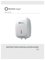
4. PRINCIPAL FUNCTION
A heat pump is capable of transferring thermal energy from a low temperature source to
another with a higher temperature and vice versa. It uses circuit consisting of a compressor,
an evaporator, a condenser and a throttle valve. A liquid/gas coolant flows inside this circuit.
The compressor creates a difference in pressure inside the circuit that allows a thermodynamic
cycle to be obtained. This sucks the coolant fluid in through an evaporator, where the fluid
itself evaporates at a low pressure by absorbing heat; it is compressed and driven towards
the condenser where the fluid condenses at a high pressure releasing the absorbed heat.
After the condenser, the fluid passes through the so-called “throttle valve” and by losing
pressure and the temperature starts to vaporize, it re-enters the evaporator and the cycle
starts all over again.
I-II: The coolant fluid sucked in by
the compressor, flows inside the
evaporator and while it evaporates,
it absorbs the “ecological” heat
given by the air. At the same time,
the ambient air is sucked in by the
equipment by a fan; the air loses
its heat by passing over the finned-
tube battery of the evaporator;
II-III: The coolant gas passes inside
the compressor and it undergoes
an increase in pressure that causes
a rise in temperature; transforming
this into superheated steam;
III-IV: Inside the condenser, the
coolant gas releases its heat to
the water inside the tank (boiler).
This exchange process makes it possible for the coolant to pass from superheated steam to a
liquid state by condensing at a constant pressure and undergoing a reduction in temperature;
IV-I: The liquid coolant passes through the throttle valve. It undergoes a sudden drop in
both pressure and temperature and it partially vaporizes bringing pressure and temperature
back to the initial conditions. The thermodynamic cycle can begin.
Fig 1 - Principal function of a heat pump

6
5. MANDATORY INSTALLATION KITS
IMPORTANT
As this product is an unvented domestic hot water heater, it is mandatory that it be installed
using a Rointe installation kit and by a professional with a valid Unvented Water Heater Installer
certification. The installation kits are NOT supplied with this product. They must be purchased
separately. They comply with Building Regulations Section G3.
Please contact us on 0203 321 5929 if you have not purchased an appropriate installation kit for
this product BEFORE installation. The T/P valve is factory fitted with the product as standard.
Fittings supplied with installation kit (sold separately) KITW03
Expansion vessel
18 litres
(0.1 Mpa)
Tundish
15 - 22 mm
Pressure reducing valve
0.35 Mpa
Safety relief valve 0.60 Mpa
EAN CODE 8436045914354
6. SAFETY INFORMATION AND WARNINGS
Please read this information carefully. If you have any questions, please contact us.
This symbol indicates a safety warning or a hazard of an electrical nature.
This symbol indicates general warnings of actions that could result in damage to the product
or injury to the installer/user/person.
This symbol indicates information or advice for operation of the product.

7
DALIS PRO DOMESTIC HOT WATER HEAT PUMP
EN
Do not open or disassemble the product when it is connected to a power supply. Isolate all
electrical supplies from the product before commencing work. Danger of electric shock.
The maintenance of this appliance must be carried out by suitable qualified persons
only. It is recommended to maintain the product on an annual basis. Isolate all power
supplies from the product before commencing work. Danger of electric shock.
It is important that the tundish is positioned away from any electrical components.
Means for electrical disconnection must be incorporated in the fixed wiring in
accordance with wiring rules.
Before removing the cover from the product isolate the appliance using the isolating
switch. Danger of electrical shock. Only use suitable electrically insulated equipment
when working inside product housing.
Do not touch the equipment when barefoot or with wet or damp body parts.
This product must only be installed and operated by competent adults. Children must
not play with the product. The product must not be cleaned, nor any maintenance made
by children.
No isolating device may be fitted between the inlet group and the cold water inlet on the
cylinder, as by doing so important safety devices could be isolated.
Do not sit on, rest anything on, move from an upright position or place anything inside the
product.
The cylinder must be filled with water before switching on. Failure to do so will damage the
heating element and the guarantee will be invalid.
The appliance should be installed in a place where it is not exposed to damp, frost or ice
and is not at risk of being splashed with water. Do not spray or pour water into the product.
This product has not been designed, nor is it intended for use within hazardous
environments (due to the presence of potentially explosive atmospheres – according to
ATEX standards or with a requested IP level exceeding that of the product) or in
applications that require (fault-tolerant, fail-safe) safety characteristics such as in
circuit-breaking systems and/or technologies or in any other context in which the
malfunctioning of an application could cause death or injury to people or animals or seri-
ous damage could be caused to objects or the environment.
If the product fails, it could cause damage to people or animals, or cause damage to
objects or the environment. If necessary, please provide an independent monitoring
system with alarm functions to avoid such damages.
We (Rointe) are not responsible, under any circumstances, if the product is used for
purposes other than those for which it is intended, or improper use of the product.

8
7. TECHNICAL INFORMATION
7.1. Available versions
Version Description
DWI200DHW5 / DWI260DHW5 Air source heat pump for production of domestic hot water.
DWI200DHWI5 / DWI260DHWI5
Air source heat pump for production of domestic hot water
suitable for use with a solar power system or additional heating
unit.
7.2. Specification
Models with heat exchanger Models without heat exhanger
Models DWI200DHWI5 DWI260DHWI5 DWI200DHW5 DWI260DHW5
Volume (L) 200 260 200 260
Load Profile L XL L XL
Power supply (V [Hz]) 1 / N / 230 (50) 1 / N / 230 (50) 1 / N / 230 (50) 1 / N / 230 (50)
Nominal power (W) 1,500 1,500 1,500 1,500
Maximum absorption (kW) 2,000 2,000 2,000 2,000
Average heat pump
consumption (kW)
0.43 0.466 0.43 0.466
Thermal power yield; prated
(kW)
1.1 1.2 1.1 1.2
Coefficient of Performance
(COP)
2.8 3.0 2.8 3.0
Heating time (hrs:min) 08:59 10:15 08:59 10:15
Heating time Boost mode
(hrs:min)
03:47 04:21 03:47 04:21
Maximum settable temperature 70ºC 70ºC 70ºC 70ºC
Established temperature 55ºC 55ºC 55ºC 55ºC
Annual electricity consumption
(kWh)
867 1,355 867 1,355
Dimensions
Diameter x height (mm) 630 x 1,720 630 x 2,010 630 x 1,720 630 x 2,010
Characteristics
Empty weight (kg) 121 128 105 110
Weight when water filled (kg) 321 388 305 370
Heat exchanger for auxillary
power source
Y Y N N
Interal solar coil (m
2
) 1 1.2 - -
Finish Grey Grey Grey Grey

9
DALIS PRO DOMESTIC HOT WATER HEAT PUMP
EN
7.3. Characteristics
1
Heat pump
22
Condensates drain (G 3/4”)
2
Control panel
23
Solar coil (G 1”)
3
External PVC jacket
24
Cold water inlet connection (G1”)
4
Enameled storage tank
25
50 mm polyurethane insulation
5
Upper storage tank probe. “T3”
26
High pressure switch – automatic reset
6
Lower storage tank probe. “T2”
27
Safety thermostat, manual reset
7
Refrigerant recharge needles
28
Controller box
8
Ambient air recirculation fan
29
Probe for solar coil thermosensor
9
Electronically regulated expansion valve
30
Low pressure switch – automatic reset
10
High-efficiency finned evaporator
31
4-way defrosting valve
11
Air inlet (Ø160 mm)
32
Upper decorative panel
12
Air outlet (Ø160 mm)
33
Back decorative panel
13
Hermetically-sealed rotary compressor
34
Front decorative panel
14
Compressor’s accumulator
35
Lower decorative panel (condense trap)
15
(1.5 kW – 230 W) heating element
36
Condenser
16
Condenser outlet line - liquid
37
Protective fan grid
17
Condenser inlet line – hot gas
38
Return gas temperature “T5”
18
Replaceable magnesium anode
39
Coil temperature “T4”
19
Hot water outlet connection (G 1”)
40
Bolts M6x60
20
Recirculation fitting (G ¾”)
41
Ambient temperature “T1”
21
Evaporator’s distributor
Fig 2 - Heat pump characteristics

10
Fig 2 - Heat pump characteristics
Description -
Dalis
200DHW5
Dalis
200DHWI5
Dalis
260DHW5
Dalis
260DHWI5
Heating time (1)
• EN 16147:2017 - A7/W55)
h:m 08:59 10:15
Heating time in BOOST mode (1)
• (A7/W10-55)
h:m 03:47 04:21
Average heat pump power consumption at
initial heat up Weh-HP / t
h
• (EN 16147:2017 - A7/W55)
kW 0.426 0.420
Power consumption, standby period; P
es
• (EN 16147:2017 - A7)
kW 0.42 0.51
Daily electrical energy consumption; Q
elec
• (EN 16147:2017 - A7)
kWh 4.184 6.499
COPDHW;
• (EN 16147:2017 - A7/W55)
- 2.8 3.0
Water heating energy efficiency;
ηŋ
WH
/ ErP class
• (EN 16147:2017 - A7/W55)
% 118 / A+ 124 / A+
Annual electrical energy consumption; AEC
• (EN 16147:2017 - A7/W55)
kWh/a 867 1354
Maximum volume of mixed water at 40ºC
• (EN 16147:2017 - A7/W55)
I 272 262 338.1 350.8
Reference hot water temperature; η0’
WH
ºC 53.6 53.7

11
DALIS PRO DOMESTIC HOT WATER HEAT PUMP
EN
Description
Dalis
200DHW5
Dalis
200DHWI5
Dalis
260DHW5
Dalis
260DHWI5
Rated heat output; Prated
• (EN 16147:2017 - A7/W55)
kW 1.05 1.20
Maximal heat output (Summer condition) kW 2.305 2.305
Dimensions (diameter x height x depth)
mm 630 x 1,720 x 600 630 x 2,010 x 600
Electrical data
Power supply V 1/N/230
Frequency Hz 50
Degree of protection - IPX4
Max. absorption kW 0.50
Average power absorption kW 0.37
Heating element + max. absorption kW 2
Power kW 1.5
Max. current A 2.3
Overload protection A
16A T fuse / 16A automatic switch, characteristic C
(to be expected during installation on power supply
systems
Internal protection - Single safety thermostat with manual reset
Functions
Min.÷ max temperature heat pump air intake
(90% R.H.)
°C -10 ÷ 43
Min. ÷ max temperature installation site °C 4 ÷ 40
Working temperature
Max. programmable temperature - ECO °C 56
Max. programmable temperature - AUTO °C 70
Compressor (rotary) & fan (centrifugal)
Compressor protection - Thermal circuit breaker with automatic reset
Ejection outlet diameter mm 160
Available external pressure of heat pump fan Pa 77
Nominal air capacity m
3
/h 315 (98 Pa)
Max. pressure head available Pa 100
Motor protection - Internal thermal circuit breaker with automatic reset
Condenser
Aluminium, wrapped externally, not in contact with water
Refrigerant R134a (charge)
g 880
Water storage
Capacity litres 200 260
Actual water storage capacity Vm litres 202 194 251 260
Max. volume hot water Vmax (3) litres 276 342
Connection coil solar thermal power system m2 n/a 1 m
2
n/a 1.2 m
2
Cathodic protection mm 2 x Mg anode Ø33 x 250; G1 1/4”
Insulation
- 50mm rigid PU
Defrosting
- Active with “4-way valve”
Sound power indoors Lw(A) (4) dB (A) 53
Automatic anti-legionella cycle (5) - YES
Maximum working pressure
bar 7

12
(1) temperature of incoming air supply 20°C (max.15°C), temperature of water heater storage environment 20°C,
water heated from 10°C to 55°C, (according to EN 16147-2011). (2) measurements carried out according to EN
12897-2006. (3) measurements carried out according to EN 16147-2011. (4) measurements carried out according
to EN 12102-2013. (5) Automatic activation - 30 day cycle.
8. BEFORE INSTALLATION
IMPORTANT
Failure to observe these instructions will invalidate the guarantee. Installation of this product is
subject to the H&S At Work act. This product must be installed by qualified professionals, cer-
tified for Unvented Water Heaters. Do not attempt to install this product if you are not qualified.
8.1. Handling and transport
• Do not put any pressure on the upper part as it is not structural in nature. The product
must be transported and handled in the upright position only. The screen should be
facing the upper side. If tipped, the centre of gravity will shift. Handle with care.
• For transport over short distances (provided it is done with care), an inclination angle
up to 30 degrees is permitted. It is advised that the maximum permissible inclination
angle of 45 degree is not exceeded. If transport in an inclined position cannot be
avoided, the unit should be left in its final, upright position for at least 1 hour before it
is installed or switched on.
Positions allowed Positions not allowed

13
DALIS PRO DOMESTIC HOT WATER HEAT PUMP
EN
8.2. Packaging
• If the product is not installed immediately, it should remain in its protective packaging
with all pipe/end caps in place to prevent damage or dirt deposits.
• Use a forklift or pallet truck to unload the equipment: these should have a load capacity
of at least 400 kg. Do not drop or lower the product suddenly.
• Unpacking the product must be carried out with care so the product does not become
damaged. Ensure all the supplied fittings have been removed from the packaging.
• Keep packaging out of reach of children. Make sure that the appliance is intact and not
damaged. If in doubt, do not use or install the product and contact us.
• The equipment is supplied in a cardboard box, fixed to a pallet with screws. Please
follow the described steps bellow in order to mount three supports. You will need 2
people in order to do this safely:
1. Incline the
appliance.
2. Unscrew the 3
bolts which hold the
heat pump to the
water heater.
3. Mount the
adjustable feet to
the heat pump.
4. Move the heat
pump to its final
vertical position
and adjust the level
using the feet.
If the adjustment feet are delivered in separate parts, assemble them as follows:
1. Put part 1 on bolt 2 (which is removed from
the pallet).
2. Put washer 3 over part 1 (which is removed
from the pallet).
3. Screw nuts 4 over washer 3 (which are
delivered with the heat pump).

14
The heat pump must be (in compliance with
Article 20 of Standard EN 60335-1) fixed to the
ground using the bracket provided.
8.3. Location
Please adhere to the following conditions when choosing a location to install the product:
• Must be installed in a dry, frost-free environment, with containment systems in case
of serious water leaks.
• Not measure less than 20 m
3
.
• Must have structural integrity that is sufficiently robust to support the product weight
when full of water, plus a flat and level surface on which to install the product.
• Must allow access to water mains supply, hot and cold water pipework and a suitable
electrical supply.
• Be readily available for connection to condensation discharge pipe.
• Be sufficiently ventilated and illuminated (if necessary) and in a space of at least 20m
3
.
• Care must be taken when installing the product in a garage or outbuilding. All exposed
pipework must be sufficiently insulated to avoid frost or ice damage.
• When installing the product, ensure that all labels are visible and pipework does not
restrict any work that needs to be carried out on the various components
• It’s important to allow the necessary working space by referring to the dimensions
show in Fig 3 below.
Fig 3 - Location conditions

15
DALIS PRO DOMESTIC HOT WATER HEAT PUMP
EN
X1 X2 X3 Y1
650 mm 650 mm 200 mm 300 m
The product MUST NOT be installed in locations where:
• The air intake contains solvents, explosive matter, grease, dirt or dust / aerosol
particles.
• It is outdoors/in rooms exposed to frost, ice or damp, or in rooms where there is a lot
of steam/vapour (e.g. a bathroom).
• It is sat on floor slabs containing wooden beams e.g. attics, to avoid vibrations.
• It is prohibited to connect vented exhaust hoods to ventilation systems.
8.4. Ventilation
When carrying out the installation of each air duct take care that:
• The weight of the ducts does not adversely affect the equipment itself.
• Maintenance operations can be carried out.
• They are adequately protected to prevent the intrusion of material inside the equipment.
• The maximum allowable total pressure drop for all components, including through
holes for external wall mounting, within the piping system must not exceed 77 Pa.
Fig 4a - Example of an air outlet duct
An alternative solution is indicated in Fig 4b. This consists of a second duct that draws air
in from outside instead of directly from inside the premises.

16
Fig 4b - Example of a dual duct connection
• During operation, the heat pump tends to lower the room temperature if the exhaust
air is not ducted externally.
• An appropriate protection filter must be installed at the external air outlet to the outside,
in order to prevent foreign bodies from entering the equipment. In order to guarantee
maximum device performance, the grid chosen must ensure low pressure loss.
• To prevent condensation, it is advisable to insulate the air discharge pipes and the air
duct cover connections with an airtight thermal lining of a suitable thickness.
• If deemed necessary to prevent flow noise, silencers can be fitted. It is advisable to
equip pipes, walls and connections to the heat pump with vibration damping systems.
WARNING
The simultaneous operation of an open flue firebox (e.g. an open flue fireplace) or combustion
chamber together with the product will cause a dangerous drop in ambient pressure. This could
cause blackflow of exhaust gas into the environment. Do not use the product with an open flue
firebox or combustion chamber. Use only sealed (approved) chamber fireboxes or combustion
chambers with a separate duct for combustion air. Keep room doors closed and hermetically
sealed if they don’t have a supply of combustion air in common with inhabited areas.
To avoid mixing of air at different temperatures between the inlet and outlet, always use two el-
bows mounted in opposite directions when ductless installation is carried out.

17
DALIS PRO DOMESTIC HOT WATER HEAT PUMP
EN
WARNING
All technical parameters stated above are guaranteed for an air flow rate of 315 m3/h at a pres-
sure of 98 Pa. For this purpose, please follow the recommendations below:
1. Use a pipe system with a diameter of Ø 160mm.
2. The maximum length of the straight inlet and outlet pipes must not exceed 12 m.
3. Each 90° elbow is equivalent to 2 m of straight pipe.
4. Each 45° elbow is equivalent to 1.5 m of straight pipe.
Suitable examples:
Four 90º elbows + 4m of straight pipe, or two 90º elbows + 8m of straight pipe, four 45º elbows
+ 6m of straight pipe.
8.5. Special installation conditions
One of the unique features of heat pump heating systems is that they create a considerable
drop in air temperature usually expelled outdoors. The expelled air, in addition to being
colder than the air in the environment, is also fully dehumidified. This means that the flow
of air can be fed back inside the building again to cool rooms or spaces during warmer
months, such as the summer. The discharge pipe should be split to which 2 valves should
be installed, so that the expelled air flow can be directed either indoors or outdoors.
Fig 5b - Installation in summerFig 5a - Installation in winter

18
9. INSTALLATION
9.1. Installation diagram
INSTALLATION ITEMS
1
Mains cold water supply
2
Stop cock (not supplied)
3
Pressure reducing valve (in
mandatory installation kit sold
separately)
4-5
Check valve & expansion relief
valve (in mandatory installation kit
sold separately)
6
Discharge pipe 22 mm
7
Drain valve (not supplied)
8
Tundish (in mandatory installation
kit sold separately)
9
Expansion vessel (in mandatory
installation kit sold separately)
10 T/P relief valve (included)
11 Electrolytic fittings (included)
Water flow
Cold water inlet
CW
to tap
Hot water outlet
1
2
5
3
4
9
8
7
10
300 mm MIN
100 mm MAX
6
11
11
Fig. 1 - Operation
Ecological heat
Fi
Click
IP 24C
TCOD: RD6154311
REF: DIW0550RAD
INPUT: 230 V~ 50Hz 550W
S/N: 8436045913715000001
D SERIES
REFERENCE
SERIAL NUMBER
DWI200DHWI4
Weight when full
Capacity
Frequency
Rated power HP
Refrig. quantity
ICO 2 eq
Heating elements
Contains fluorinated greenhouse gases
SERIAL NO.
Max working press.
Power supply
Max power
Refrigerant
GWP
Heating capacity HP
Max pressure
250 Kg
200 litres
50 Hz
370 W (500 W max)
0.90 Kg
1.287
1500 W
7 bar (0.70 MPa)
230 V
2000 W
R134a
1430
1600 W
2.4 MPa / 1MPa
843604591307403673700000000
IPX4
Fig 6 - Installation diagram
When carrying out the installation you must take care, so that:
• Extra pressure is not applied to the product e.g. by leaning on it.
• Foreign bodies and materials cannot enter inside the product.
• The selected pressure protection grid ensures low pressure loss.
• The air discharge pipes and roof connections are isolated with steam-tight thermal
coating to avoid condensation.
9.2. Cold water supply
For safe performance of the product, the tank should be directly fed by an uninterrupted
supply pipe that connects to the pressure reducing valve with a maximum supply pressure
of 0.9 MPa. The product should not be used with a supply pressure below 0.15 MPa and a
flow rate of less than 20 litres per minute. The following criteria must also be met:
• Cold water supply must come directly from the cold water mains after the mains stop
valve to the property.
• The inside diameter of the cold water pipework must be at least 19mm.
• Pipework should meet the water supply regulations for wholesome water.

19
DALIS PRO DOMESTIC HOT WATER HEAT PUMP
EN
9.3. Connections
9.3.1. Overall dimensions
R
Fig 7 - Heat pump dimensions
Dimensions
(+/- 5mm)
260 litres model 200 litres model
Dimensions
(+/- 5mm)
260 litres model 200 litres model
h
2010 1720
n
766* 681*
a
1285 994
u
1440 1153
b
834 724
w
58 58
d
1285 995
M
260 260
f
1064 803
ØDF
160 160
j
781* 681*
R
2055 1785
k
60 60
ØD
630 630
* For models with heat exchanger only.
No.
Description
Connection
(with heat exchanger)
Connections
(without heat exchanger)
CW
Cold water inlet G 1” G 1”
HW
Hot water outlet G 1” G 1”
IS
Heat exchanger input G 1” -
OS
Heat exchanger output G 1” -
TS
Thermosensor G 1/2” -
R
Recirculation G 3/4” G 3/4”
EE
Opening for electric element G 1 1/2” G 1 1/2”
CD
Condense drainage G 3/4” G 3/4”
ThS
Thermal safety thermostat - -
MA
Magnesium anode G 1 1/4” G 1 1/4”
Thread designations according to EN ISO 228-1

20
9.3.2. Water supply connections
IMPORTANT
When the water hardness is particularly high (above 25°F), it is advisable to use a water softener,
properly calibrated and controlled. The resulting water hardness must not be less than 15°F.
This product is equipped with a pressure and T/P valve that complies with the BS EN 1490:2000
standard. The T/P safety valve for protection against over pressure and temperature must be op-
erated regularly to remove lime scale deposits and check it is not blocked.
WARNING
Use of this appliance at temperatures and pressures higher than those prescribed will invalidate
the guarantee.
This appliance is intended for heating potable water in a liquid state. The use of different fluids in
different states will also invalidate the guarantee.
The heat exchangers of the device are intended for the use of circulating clean water and its mix-
ture with propylene glycol in liquid form. The presence of anti-corrosion additives is mandatory.
The use of different fluids will invalidate the guarantee
Dissimilar metals cause galvanic corrosion. Therefore, pipes, joints and fittings made of
dissimilar metals must be connected to the device by means of dielectric separators.
Plastic pipes (PP) are permeable to oxygen. It is prohibited to connect the heat exchanger to sys-
tems with PP or open circulation pipes. This can lead to corrosion inside the pipe.
It is mandatory to install a 7 bar safety valve (No. 5 in Fig 8) in the cold water inlet pipe.
It is forbidden to install any shut-off valve or tap between the safety valve and the storage tank.
The safety equipment must be operated regularly to remove scale deposits and to check that it
is not blocked.
The drain pipe (No. 6 in Fig 8) connected to the safety valve must be installed sloping continuously
downwards and, in a place, where it is protected against the formation of ice (Fig 8).
Using a tundish is obligatory. The drain pipe must be made by a material that is able to sustain
water temperature minimum 110ºC.
An expansion vessel (No.10 in Fig 8) should be installed in order to absorb water expansion due to
temperature variation. Pressure regulator (No. 3 in Fig 8) and expansion vessel should be calculat-
ed together by qualified persons.
The heat pump for the production of domestic hot water is capable of heating water more than
65°C. For this reason, as a protection against burns, it is necessary to install a thermostatic mixing
valve (No. 16 in Fig 8) to the hot water pipe.
/