
OWNERS MANUAL | Cobolt Modulated DPSS Lasers | D0342-C JUNE 2016
High performance DPSS lasers
with integrated AOM
457 nm
515 nm
594 nm
473 nm
532 nm
660 nm
491 nm
561 nm
Cobolt Modulated
DPSS Lasers

2 | 36
OWNERS MANUAL | Cobolt Modulated DPSS Lasers | D0342-C JUNE 2016

3 | 36
OWNERS MANUAL | Cobolt Modulated DPSS Lasers | D0342-C JUNE 2016
CONTENTS
Introduction 5
Safety 6
General 6
Safety features 7
Equipment Safety 7
Warning and Identification Labels 8
Overview 9
Model number 9
Configuration 10
Laser Head 11
Laser Controller 11
Cables 12
Thermal Management 13
Power Supply Requirements 13
System Description 14
Specification 14
Mechanical Drawings 17
Remote Interlock Connector 19
Direct ON/OFF control 19
Pin assignment 20
Operating Instructions 21
Installation start-up operation 21
Shutdown procedure operation 21
Operating Modes 22
Modulation 22
Operation via data port 24
Handshaking 24
RS232 configured controllers 24
USB configured controllers 24
Communication commands 27
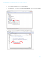
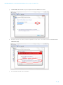
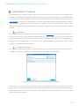
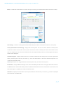
Cobolt Monitor™ Software 29
Installation 29
Software instructions 29
Troubleshooting 32
Warranty and Maintenance 32
Service 32
Compliance (CDRH models only) 33
Disclaimer 34

4 | 36
OWNERS MANUAL | Cobolt Modulated DPSS Lasers | D0342-C JUNE 2016

5 | 36
OWNERS MANUAL | Cobolt Modulated DPSS Lasers | D0342-C JUNE 2016
Introduction
The Cobolt Modulated DPSS option incorporates both the diode pumped laser (DPL) from the Cobolt 04-01 series
and an Acousto Optic Modulator (AOM) in one single compact package, slightly longer than the standard 04-01 Series
laser head.
This allows fast and effective integration of a modulated DPSSL without the need for time consuming external
alignment. AOMs are commonly used in combination with DPSSLs to achieve high speed modulation while
maintained good stability and low noise.
Utilising Cobolt’s extensive experience in optical alignment along with our proprietary manufacturing method
HTCure™ for ultra robustness, the Modulated DPSSL option offers a modulated DPSSL with the ease of integration
of a direct diode lasers and the specifications associated with high performance diode pumped lasers, such as single
frequency operation, excellent spectral purity and a perfect beam.

6 | 36
OWNERS MANUAL | Cobolt Modulated DPSS Lasers | D0342-C JUNE 2016
Safety
General
Cobolt Modulated DPSS Lasers are Class IIIB (CDRH), Class 3B (IEC) laser products emit less than 500 mW of laser
radiation within the visible spectrum. Residual emissions from the pump diode are contained within the laser head
housing via filtering optics. The residual emission does not exceed Laser Class 1.
Eye and skin exposure to direct or reflected laser light is hazardous and may be extremely harmful. Always wear eye
protection appropriate to the beam wavelength and intensity. Class 3B lasers may pose a risk of igniting flammable
materials and in event of ignition gasses and fumes may be generated. All equipment used in close proximity to the
laser beam should be suitably fire resistant and the facility should be properly ventilated. It is advised to perform a
risk assessment for the facility and equipment prior to using the laser. In the case of integration into a larger system,
laser safety compliance must be evaluated on the end product.
The device must be handled by skilled personnel experienced with lasers, in a laboratory environment and with access
to adequate laser safety equipment. The laser head clearly displays a yellow warning label that shows the location of
the laser beam aperture. This label must be visible unless the laser beam is totally enclosed.
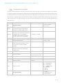
The table below describes the irradiance in W/cm
2
and appropriate level of eye protection in terms of optical density
(OD) for each product line.
Product
Nominal Output Power
(mW)
Irradiance
(W/cm
2
)*
Eye protection
Requirement**
Twist™ 457nm
40
13
> OD 4
Blues™ 473nm
40
13
> OD 4
Calypso™ 491nm
80
27
> OD 4
Fandango™ 514.4nm
120
40
> OD 4
Samba™ 532nm
320
106
> OD 4
Jive™ 561nm
160
53
> OD 4
Mambo™ 594nm
80
27
> OD 4
Flamenco™ 660nm
80
27
> OD 4
* Irradiance (W/cm2) = 110% of Nominal Power (W) Beam Area at bottom tolerance (cm2)
** Eye protection (OD) = Log
10
( Max Power (W) 60825-1 Emission Limit : Class 1 (W) ) , rounded up to the next integer.

7 | 36
OWNERS MANUAL | Cobolt Modulated DPSS Lasers | D0342-C JUNE 2016
Safety features
The laser is equipped with all required safety features as described in the laser safety standard 60825-1. Disabling any
safety features negate the CE/CDRH compliance of this product.
Remote Interlock Connector
The remote interlock connector is a connector which permits the connection of external controls placed apart from
other components of the laser product. When the terminals of the connector are open-circuited, emission is
interrupted and no radiation will be accessible. The remote interlock connector permits easy addition of an external
interlock in laser installation. See section 4.3 for a detailed description of the remote interlock circuit and operation.
Manual Shutter (Beam Stop)
The laser head is equipped with a manual shutter, which functions as the beam stop, capable of preventing human
access to laser radiation. The aperture location and the open and close positions of the shutter are indicated on the
top surface of the laser head.
Key Control
The CDRH compliant model comes with a key-switch on the Controller which must be connected for the laser to
operate. When the key is in the OFF position, the laser is prevented from emitting. The key must be actively turned
to the ON position each time the laser is powered on. When the key is removed from the system laser radiation is not
accessible.
Laser Radiation Emission Warning
The Controller incorporates information LEDs which display whether power is connected, the laser is on, or a fault has
occurred. The “ON” LED is illuminated whenever the device is emitting or could emit light. See section 3.4 for details
on the controller. The emission warning indicators are also visible in the Cobolt Monitor™ software, see section 8 for
details on the control software
Equipment Safety
Always install all power supplies used in the laser system to properly grounded power outlets. The laser head, laser
controller and AOM driver must be mounted on a common ground plane, such as an optical table. Cobolt lasers
contain a laser diode which is sensitive to electrostatic discharge (ESD).

8 | 36
OWNERS MANUAL | Cobolt Modulated DPSS Lasers | D0342-C JUNE 2016
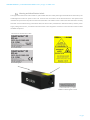
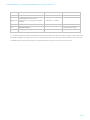
Warning and Identification Labels
The upper face of the laser head contains a yellow label with laser safety warning and classification information, the
wavelength and maximum power of the unit. It also shows the location of the laser beam from the aperture and
indicates the open and close positions of the manual shutter. This label must be visible unless the laser beam is totally
enclosed. A silver label showing information about the laser model, manufacturer date and location, and the power
supply voltage and current, is located on the laser head. Lasers shipped to customers in the USA also contain a label
of CDRH compliance.
Laser Notice No. 50 Label
CDRH models shipped to USA
CE marking for CDRH models only
OEM Label
Aperture Warning Labels
Manufacturer Identification Labels

9 | 36
OWNERS MANUAL | Cobolt Modulated DPSS Lasers | D0342-C JUNE 2016
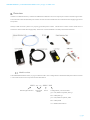
Overview
In order to modulate the laser, at least one additional modulation source is required, for instance a function generator.
The Controller Cable should always be used to connect the Laser Head with the Controller before supplying power to
the system.
Always install the laser system to a properly grounded power outlet. Cobolt lasers contain a laser diode which is
sensitive to electrostatic discharge (ESD). The device must be handled in an ESD protected workstation.
Model number
Cobolt Modulated DPSS Lasers (04-05) models are sold in two configurations: CDRH and OEM, described in section
0. The model numbers are composed as described below.
Wavelength Indicator
Laser Head
Model
Power
Configuration, communication:
500 = CE / CDRH compliant, RS-232
600 = OEM, RS-232
700 = CE / CDRH compliant, USB
800 = OEM, USB
xxx = OEM customization
XXXX – 04 – 05 – XXXX – XXX

10 | 36
OWNERS MANUAL | Cobolt Modulated DPSS Lasers | D0342-C JUNE 2016
Configuration
CDRH Compliant
The CDRH compliant system is supplied with a key switch on the Controller, which must be connected, along with a
remote interlock connector. Once power is supplied, laser radiation starts when the key is turned from the OFF
position to the ON position. The laser radiation will not be emitted from the aperture until the AOM receives the
appropriate signals, see section 5.1 for start-up instructions. The status of operation can be monitored via LEDs on
the Controller. Setting the key to its OFF position puts the laser in stand-by mode. The CDRH model is CE compliant.
The standard CDRH model consists of:
Laser head with Integrated AOM
Laser Controller with key switch
Keys
1(m) Laser Controller Cable
12V/3.75A power supply unit for Laser Controller
Remote interlock jumper (for short circuiting the remote interlock connector)
Data communication cable
AOM driver
24V/1.25A power supply for the AOM driver
RF cable
Digital modulation cable
Analogue modulation cable
5V power supply (can be used to provide a constant digital “on”)
OEM
The OEM system is supplied without a key switch on the controller. Connecting the power supply to the controller
initiates an automatic start-up sequence. If the remote interlock is connected, laser radiation will start automatically
as soon as power is supplied and internal temperatures are stabilized. The laser radiation will not be emitted from the
aperture until the AOM receives the appropriate signals, see section 5.1 for start-up instructions.
The OEM model consists of:
Laser head
Laser Controller
Laser Controller Cable
12V power supply unit
Remote interlock jumper (for short circuiting the remote interlock connector)
Data communication cable
AOM driver
24V/1.25A power supply for the AOM driver
RF cable
Digital modulation cable
Analogue modulation cable
5V power supply (can be used to provide a constant digital “on”)

11 | 36
OWNERS MANUAL | Cobolt Modulated DPSS Lasers | D0342-C JUNE 2016
Laser Head
The Laser Head contains a pump diode, laser cavity, beam shaping optics and thermoelectric coolers (TEC) routing
optics and an integrated AOM. The laser head contains an optical feed-back loop which measures the output power.
The Laser Head gets electrical power and control signals from the Controller via a 26-pin HD Sub-D cable. The AOM
does not require electrical power. There is an SMA connector on the laser head for the input modulation signals.
Laser Controller
The Controller supplies driving current and control signals to the Laser Head. All Laser Heads are delivered with a
controller. The operation set points are specific to each Laser Head and have been fixed during manufacturing. The
operation set points are stored in the laser head so the controller can be interchanged or replaced.
The status of the laser operation is given via LED indicators:
POW
(green light)
Power is supplied.
ON
(orange light)
Laser light is on in constant current mode.
LOCK
(orange light)
Laser light is on and the output power has been locked to set point. The laser is
operating according to specifications.
ERR
(red light)
An error has occurred. No laser light.
When power is supplied to the Controller, regardless of on/off state, the temperature control elements are operating
to reach set point values. The Controller includes a remote interlock connector, pin 1-2 according to Section 4.3. The
operation of the laser can be controlled and monitored via the data port that supports either USB or RS-232
commands. See Section 7 for further details. RS-232 controllers may also be delivered with a RS-232 to USB adaptor.

12 | 36
OWNERS MANUAL | Cobolt Modulated DPSS Lasers | D0342-C JUNE 2016
Cables
In the CDRH compliance configurations delivered the standard cables listed below, using any other cable type or
length may violate CE compliance.
Laser Controller Cable
The laser controller cable is a 1m SubD26-SubD26 cable that connects the Laser Head to the Laser Controller. The
cable has a minimum bending radius 8 cm. When connected care should be taken not to bend or break any of the 26
pins.
RF Cable
The RF cable is a 0.2m SMA-SMA cable that connects the AOM to the AOM driver.
Digital Modulation Cable
The Digital modulation cable is a 0.2m BNC-subD cable connects the AOM driver to the digital modulation source.
The digital modulation source can be any source capable of delivering a TTL digital signal. For convenience a 5V power
supply is provided which can be used as a digital modulation source delivering a constant digital “on”. This can be
useful if only analogue modulation is of interest. See the set-up instruction below for more information.
Analogue Modulation Cable
The Analogue modulation cable is a 1m BNC-SMA cable that connects the AOM driver to the analogue modulation
source.

13 | 36
OWNERS MANUAL | Cobolt Modulated DPSS Lasers | D0342-C JUNE 2016
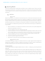
Thermal Management
To ensure operation within given specifications and for the warranty to be valid, the Laser Head must be attached to
a heat sink providing adequate thermal resistance. The required thermal resistance for low power models is <0.6 K/W
and <0.4 K/W for high power models (i.e. Calypso 80 mW, Samba 240 mW, Samba 320 mW, Jive 160 mW, Mambo
80mW, and Flamenco 80 mW). This value is the difference between the maximum allowed Laser Head base plate
temperature (50
º
C) and the maximum specified ambient temperature at the air-heatsink interface (40
º
C), divided by
the maximum power dissipated from the (15W or 25W depending on laser model, see specification below). The
mounting surface should be flat within 0.05 mm over mounting surface. It is recommended to use a thermal heat
compound between the Laser Head and the heat sink to provide good thermal contact. The Cobolt ‘HS-03 Laser Head
Heatsink’ meets these requirements, see www.cobolt.se for more information on heat sinks. For assistance in thermal
management and system integration, please contact Cobolt technical support.
Heat Sink Requirements and typical maximum heat dissipation for Cobolt 04 Series. *High power applies to the following models
only: Calypso 80 mW, Samba 340 mW, Samba 320 mW, Jive 160 mW, Mambo 80mW, and Flamenco 80 mW.
AOM Driver Heat Sink
The AOM driver requires a heat sink <1.2K/W.
Power Supply Requirements
An appropriate Power Supply Unit (PSU) is supplied by Cobolt with the laser and must be plugged into a properly
grounded standard power outlet. The output from this PSU is 12 VDC/3.75 A. The power supply accepts 100 – 240 V
AC and 50-60 Hz. Ripple and noise 1% peak-peak max, 20 MHz bandwidth. The accepted voltage range is 11 V - 28
VDC.
A 24V power supply for the AOM driver is also supplied and should be connected to the input marked +VDC on the
AOM driver.
A 5V power supply is supplied with the system to allow for generation of a simple constant TTL digital ‘ON’ state.

14 | 36
OWNERS MANUAL | Cobolt Modulated DPSS Lasers | D0342-C JUNE 2016
System Description
The information presented here is believed to be accurate and is subject to change without notice. The specifications
contained herein cannot be guaranteed outside of normal operational conditions. The output power can be adjusted
using control commands, see Section 7.4. Specifications are guaranteed at 100% of nominal power.
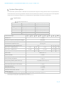
Specification
Optical Specifications
Centre wavelength (nm)
1
Output power (mW)
Twist™
457.0 ± 0.3
25, 40
Blues™
473.0 ± 0.3
25, 40
Calypso™
491.5 ± 0.3
25, 50, 80
Fandango™
514.4 ± 0.3
25, 50, 100, 120
Samba™
532.1 ± 0.3
25, 50, 100, 150, 240, 320
Jive™
561.2 ± 0.3
25, 50, 100, 120, 160
Mambo™
593.6 ± 0.3
25, 50, 80
Flamenco™
659.6 ± 0.3
80
1. The wavelength is fixed with this accuracy, while drift is defined as Wavelength stability. The wavelength is specified in air.
2. The exit window is located optically ~20cm before the laser head shutter.
3. Predominantly due stray light, fiber coupling will further improve the extinction ratio.
Product Wavelength
457
473
491
514
532
561
594
660
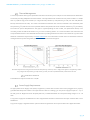
Rise/Fall time
< 200ns
Modulation Frequency (analogue and digital)
DC-3MHz
Extinction Ratio (free space)
3
> 30 dB (DC)
Beam diameter at Aperture (1/e
2
)
700 ± 50 µm
Beam divergence (mrad, full angle, 1/e
2
)
< 1.2
< 1.3
< 1.5
Noise 20 Hz – 20 MHz (pk-pk)
< 2 %
< 3 %
< 2 %
< 3%
< 1 %
Noise 20 Hz – 20 MHz (rms)
< 0.25 %
< 0.3 %
< 0.25 %
< 0.3%
< 0.1%
Long-term power stability (8 hours)
< 2 %
< 3 %
< 2 %
< 3 %
< 2 %
Spatial mode
TEM
00
, M
2
<1.1
Spectral linewidth
< 1 MHz
Wavelength stability (after warm-up)
2 pm over ± 2 ºC and 8 hrs
Beam symmetry at aperture
> 0.95 : 1
Beam pointing stability (after warm-up)
< 20 µrad/
º
C (over 10-40
º
C)
Coherence length
> 100 m
Beam waist location (from exit window)
2
20 cm
Beam angle accuracy
< 5 mrad
Beam position accuracy
< 0.25 mm
Polarization ratio (linear, vertical)
> 100:1
Residual IR emission
< Class 1

15 | 36
OWNERS MANUAL | Cobolt Modulated DPSS Lasers | D0342-C JUNE 2016
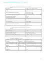
Operation and Environmental Specifications – Laser Head
Power supply
12 VDC, 3.75 A, 11-28 VDC accepted
Power consumption, total system (Laser Head + Controller)
<25 W (typical ~15 W)
< 35 W (typical ~25 W) *
Maximum heat dissipation of Laser Head
<15 W (typical ~10 W)
< 25 W (typical ~15 W) *
Maximum Laser Head baseplate temperature
50
º
C
Ambient temperature, operation
10-40
º
C
Ambient temperature, storage
0-60
º
C
Warm-up time, from OFF
< 3 min
Humidity
0-90% RH non-condensing
Ambient Air pressure
950-1050 mbar
Heat sink thermal resistance, Laser Head
<0.6 K/W
<0.4 K/W *
* Applies to high power models: Calypso 80 mW, Samba 240 mW, Samba 320mW, Jive 160 mW, Mambo 80mW, Flamenco 80 mW
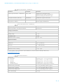
Operation and Environmental Specifications – AOM Driver
Power supply
24VDC, 1.25A
Power consumption
< 12 W
Ambient temperature, operation*
10–40°C (max T
case
55°C)
Ambient temperature, storage
-40°C - +50°C, non-condensing
Heat sink thermal resistance, AOM driver
<1.2 K/W
Warm-up time
10 min
Electrical Interfaces - Controller
Interfaces
Connector
Function
Input power
Kycon KPJX-45, 4-pin
Power supply to Controller
Laser Head to Controller
HD-sub 26-pin, male
Connection to Laser Head
Controller to Laser Head
HD-sub 26-pin, female
Connection to Controller
Data port
USB-type mini B
Control and monitoring via control commands
Remote interlock &
Analog signals
Molex 90130-3206
Analog input 5 – 12 V => Laser ON
Analog input <2.7 V => Laser OFF
Warm-up time
2 min

16 | 36
OWNERS MANUAL | Cobolt Modulated DPSS Lasers | D0342-C JUNE 2016
Electrical Interfaces – AOM Driver
Interfaces
Connector
Function
Control input connector – AOM Driver
DB 15, male
Digital (TTL) modulation input ,
Optional Power supply to AOM driver,
Optional Analogue modulation input
RF output connector (“RF out”)
SMA female
Modulation signal to laser head
RF modulation input (“Mod in”)*
SMA female
Analogue modulation input
Input power (“+VDC”)*
Power supply to AOM driver
Electrical Characteristics – AOM Driver
Supply voltage
+24VDC
Output impedance – RF output connector
50 Ω (nom.)
Analogue modulation
Impedance
1k Ω
Voltage range
0 – 1 V
RF ON/OFF ratio
60 dB
Absolute maximum ratings
-0.5V - +1.1V
Digital modulation
Impedance
1k Ω
vHigh level
≥3V – 5V (=RF on)
Low level
0 - <0.8V (=RF off)
RF ON/OFF ratio
70 dB
Absolute maximum ratings
-0.5V - +5.5V
For more details on the specification of the AOM driver, see the website of AA Opto-Electronics,
www.aaoptoelectronic.com
Mechanical Interfaces
Dimensions:
Laser Head
Controller
12V PSU
AOM Driver
24V Power Supply
137x60x45 mm (4.1x2.4x1.6 inches)
190x72x28 mm (7.5x2.8x1.1 inches)
130x55x30 mm (5.2x2.2x1.2 inches)
129x61x30 mm (5.1x2.4x1.2 inches)
121x50x30.8 mm (4.76x1.97x1.21 inches)
Fixation holes, Laser Head
= 4x 4.5mm (M4); 115mm x 55mm
Fixation holes, Controller
= 4x 6.4mm (M6); 178mm x 51mm
Fixation holes, AOM Driver
= 4x 4.5mm (M3); 120mm x 51mm
Laser Head weight
<0.5 kg

17 | 36
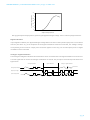
OWNERS MANUAL | Cobolt Modulated DPSS Lasers | D0342-C JUNE 2016
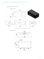
Mechanical Drawings
Laser Head
Laser head mechanical outline. Dimensions in mm [inches].
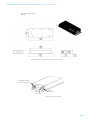
AOM Driver
AOM Driver mechanical outline. Dimensions in mm.

18 | 36
OWNERS MANUAL | Cobolt Modulated DPSS Lasers | D0342-C JUNE 2016
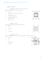
Laser Controller
Controller mechanical outline. Dimensions in mm [inches].
Connector location Controller
Power
connector
Data
connector
Analog & remote
interlock connector

19 | 36
OWNERS MANUAL | Cobolt Modulated DPSS Lasers | D0342-C JUNE 2016
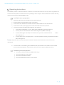
Remote Interlock Connector
The remote interlock connector is located at pin 1 and 2 of the Molex connector on the Controller. The connector can
be short-circuited with an interlock jumper (included at delivery) for operation of the laser. To use the remote interlock
connector with an external switch, connect a pin 1 and 2 on a Molex plug. After the remote interlock connector has
been opened the laser will need to be reset by disconnecting from and then reconnecting to the power supply in order
to start again. Alternatively, it can be re-started using a special sequence of commands, see Section 7.4 for further
details. The signal level is between 0V and +5V with a pull up resistor, and the current required to ground the remote
interlock connector is 5 mA. The time delay in the hardware is <1ms, but after filtering by the firmware the reaction
time is extended to < 20ms.
Direct ON/OFF control
The Direct On/Off Control feature enables turning the laser ON/OFF using a 5-12 VDC signal. After having configured
the Controller for Direct Control operation (factory set or by executing @cobasdr 1), the laser can only start-up when
5-12V VDC (max 12.5 VDC) is applied to pin 3 on the analog connector with 0 VDC on pin 2 as reference. Shifting the
signal to 0 VDC on pin 3 will turn the laser off and put the laser in stand-by mode (status LED:s is POW and not
flashing).
This function is not available for CDRH compliant models.
! Note: This input only controls the on/off state of the laser and cannot be used to modulate the power output.

20 | 36
OWNERS MANUAL | Cobolt Modulated DPSS Lasers | D0342-C JUNE 2016
Pin assignment
Analog connector & Remote interlock connector
Manufacturer Molex 90130-3206, mates with 90143-0006.
Pin
Function
1
Remote Interlock (connect to pin 2 for enable)
2
0 V - GND
3
Remote On/Off (+5V Input)
4
TST (Internal Cobolt use only)
5
LED “Laser on” (5V)
6
LED “Error” (5V)
Power connector
Kycon KPJX-4S, mates with Kycon KPPX-4P. Grounded shield.
Pin
Function
1
0 V
2
+11-28 VDC
3
0 V
4
+11-28 VDC
Data connector
Connector USB-type, manufacturer Hsuan Mao C8320-05BFDSB0, mates with connector mini-B.
Pin
Function
1
+5 V
2
D-
3
D+
4
Not connected
5
0 V (GND)
Page is loading ...
Page is loading ...
Page is loading ...
Page is loading ...
Page is loading ...
Page is loading ...
Page is loading ...
Page is loading ...
Page is loading ...
Page is loading ...
Page is loading ...
Page is loading ...
Page is loading ...
Page is loading ...
Page is loading ...
Page is loading ...
-
 1
1
-
 2
2
-
 3
3
-
 4
4
-
 5
5
-
 6
6
-
 7
7
-
 8
8
-
 9
9
-
 10
10
-
 11
11
-
 12
12
-
 13
13
-
 14
14
-
 15
15
-
 16
16
-
 17
17
-
 18
18
-
 19
19
-
 20
20
-
 21
21
-
 22
22
-
 23
23
-
 24
24
-
 25
25
-
 26
26
-
 27
27
-
 28
28
-
 29
29
-
 30
30
-
 31
31
-
 32
32
-
 33
33
-
 34
34
-
 35
35
-
 36
36


Ask a question and I''ll find the answer in the document
Finding information in a document is now easier with AI
Other documents
-
Franke 0737836 Datasheet
-
-
AGILTRON 5W 80MHz Acoustic Optic Modulator User manual
-
AMX MAX-AOM User manual
-
-
SRS LDC502 Owner's manual
-
 Aesthetix Calypso Owner's manual
-
Hitachi LM-C300S/P Quick Reference Manual
-
 Industrial Fiber Optics ML 800 User manual
-
Panasonic UJ30 User manual

