Hayward DEP80 Owner's manual
- Category
- Above ground pool accessories
- Type
- Owner's manual
This manual is also suitable for

ISDE2423 Rev D
USE ONLY HAYWARD GENUINE REPLACEMENT PARTS
1
Hayward D.E. Filter
Owner’s Manual
IMPORTANT SAFETY INSTRUCTIONS
Basic safety precautions should always be followed, including the following: Failure to follow instructions
can cause severe injury and/or death.
This is the safety-alert symbol. When you see this symbol on your equipment or in this manual, look for
one of the following signal words and be alert to the potential for personal injury.
WARNING
warns about hazards that
could
cause serious personal injury, death or major property
damage and if ignored presents a potential hazard.
CAUTION
warns about hazards that
will
or
can
cause minor or moderate personal injury and/or property
damage and if ignored presents a potential hazard. It can also make consumers aware of actions that are
unpredictable and unsafe.
The
NOTICE
label indicates special instructions that are important but not related to hazards.
Hayward Pool Products
620 Division Street, Elizabeth, NJ 07207
Phone: (908) 355-7995
www.hayward.com
Contents
Product Warnings……………….…2
Introduction……….……..…..…..…4
Installation……….……………..……4
Starting Pump and Filter…………5
Filter Control Valve…………………6
Winterizing…………………………….9
Replacement Parts………..………10
Warranty..………………………..……11
Registration……………….………….12

USE ONLY HAYWARD GENUINE REPLACEMENT PARTS
2
WARNING - Read and follow all instructions in this owner’s manual and on the equipment. Failure to
follow instructions can cause severe injury and/or death.
WARNING – Suction Entrapment Hazard.
Suction in suction outlets and/or suction outlet covers which are, damaged, broken, cracked, missing, or unsecured can cause
severe injury and/or death due to the following entrapment hazards:
Hair Entrapment- Hair can become entangled in suction outlet cover.
Limb Entrapment- A limb inserted into an opening of a suction outlet sump or suction outlet cover that is damaged, broken,
cracked, missing, or not securely attached can result in a mechanical bind or swelling of the limb.
Body Suction Entrapment- A negative pressure applied to a large portion of the body or limbs can result in an entrapment.
Evisceration/ Disembowelment - A negative pressure applied directly to the intestines through an unprotected suction outlet
sump or suction outlet cover which is, damaged, broken, cracked, missing, or unsecured can result in evisceration/
disembowelment.
Mechanical Entrapment- There is potential for jewelry, swimsuit, hair decorations, finger, toe or knuckle to be caught in an
opening of a suction outlet cover resulting in mechanical entrapment.
WARNING - To Reduce the risk of Entrapment Hazards:
o When outlets are small enough to be blocked by a person, a minimum of two functioning suction outlets per pump must
be installed. Suction outlets in the same plane (i.e. floor or wall), must be installed a minimum of three feet (3’) [1 meter]
apart, as measured from near point to near point.
o Dual suction fittings shall be placed in such locations and distances to avoid “dual blockage” by a user.
o Dual suction fittings shall not be located on seating areas or on the backrest for such seating areas.
o The maximum system flow rate shall not exceed the flow rating of as listed on Table 1.
o Never use Pool or Spa if any suction outlet component is damaged, broken, cracked, missing, or not securely attached.
o Replace damaged, broken, cracked, missing, or not securely attached suction outlet components immediately.
o In addition two or more suction outlets per pump installed in accordance with latest ASME, APSP Standards and CPSC
guidelines, follow all National, State, and Local codes applicable.
o Installation of a vacuum release or vent system, which relieves entrapping suction, is recommended.
WARNING – Failure to remove pressure test plugs and/or plugs used in winterization of the pool/spa from the
suction outlets can result in an increase potential for suction entrapment as described above.
WARNING – Failure to keep suction outlet components clear of debris, such as leaves, dirt, hair, paper and other
material can result in an increase potential for suction entrapment as described above.
WARNING – Suction outlet components have a finite life, the cover/grate should be inspected frequently and
replaced at least every SEVEN years or if found to be damaged, broken, cracked, missing, or not securely attached.
CAUTION – Components such as the filtration system, pumps and heater must be positioned so as to prevent their
being used as means of access to the pool by young children. To reduce risk of injury, do not permit children to use or climb
on this product. Closely supervise children at all times. Components such as the filtration system, pumps, and heaters must be
positioned to prevent children from using them as a means of access to the pool.
WARNING – Hazardous Pressure. Pool and spa water circulation systems operate under hazardous pressure during
start up, normal operation, and after pump shut off. Stand clear of circulation system equipment during pump start up. Failure to
follow safety and operation instructions could result in violent separation of the pump housing and cover, and/or filter housing
and clamp due to pressure in the system, which could cause property damage, severe personal injury, or death. Before servicing
pool and spa water circulation system, all system and pump controls must be in off position and filter manual air relief valve must
be in open position. Before starting system pump, all system valves must be set in a position to allow system water to return
back to the pool. Do not change filter control valve position while system pump is running. Before starting system pump, fully
open filter manual air relief valve. Do not close filter manual air relief valve until a steady stream of water (not air or air and water)
is discharged.
WARNING – Separation Hazard. Failure to follow safety and operation instructions could result in violent separation of
pump and/or filter components. Strainer cover must be properly secured to pump housing with strainer cover lock ring. Before
servicing pool and spa circulation system, filters manual air relief valve must be in open position. Do not operate pool and spa
circulation system if a system component is not assembled properly, damaged, or missing. Do not operate pool and spa circulation
system unless filter manual air relief valve body is in locked position in filter upper body. Never operate or test the circulation
system at more than 50 PSI. Do not purge the system with compressed air. Purging the system with compressed air can cause
components to explode, with risk of severe injury or death to anyone nearby. Use only a low pressure (below 5 PSI), high volume
blower when air purging the pump, filter, or piping. Use ONLY Hayward clamp system components: DEX2421JKIT clamp assembly,
DEX2421J2 nut/bolt assembly, and a DEX2422Z2 metal reinforced seal. Non-Hayward components may fail in use and cause
explosive separation.
Never rely on hand tightening the clamp nut to the clamp bolt. Using a ¾” socket on a torque wrench, torque clamp nut and clamp
bolt to 150 inch-lbs. Before starting system pump, insure filter manual air relief valve body is in LOCK position in filter upper body.

USE ONLY HAYWARD GENUINE REPLACEMENT PARTS
3
WARNING – Risk of Electric Shock. All electrical wiring MUST be in conformance with applicable local codes,
regulations, and the National Electric Code (NEC). Hazardous voltage can shock, burn, and cause death or serious property
damage. To reduce the risk of electric shock, do NOT use an extension cord to connect unit to electric supply. Provide a properly
located electrical receptacle. Before working on any electrical equipment, turn off power supply to the equipment. To reduce
the risk of electric shock replace damaged wiring immediately. Locate conduit to prevent abuse from lawn mowers, hedge
trimmers and other equipment. Do NOT ground to a gas supply line.
WARNING – Risk of Electric Shock Failure to ground all electrical equipment can cause serious or fatal electrical shock
hazard. Electrical ground all electrical equipment before connecting to electrical power supply.
WARNING – Risk of Electric Shock Failure to bond all electrical equipment to pool structure will increase risk for
electrocution and could result in injury or death. To reduce the risk of electric shock, see installation instructions and consult a
professional electrician on how to bond all electrical equipment. Also, contact a licensed electrician for information on local
electrical codes for bonding requirements.
Notes to electrician: Use a solid copper conductor, size 8 or larger. Run a continuous wire from external bonding lug to
reinforcing rod or mesh. Connect a No. 8 AWG (8.4 mm
2
) [No. 6 AWG (13.3 mm
2
) for Canada] solid copper bonding wire to the
pressure wire connector provided on the electrical equipment and to all metal parts of swimming pool, spa, or hot tub, and metal
piping (except gas piping), and conduit within 5 ft. (1.5 m) of inside walls of swimming pool, spa, or hot tub.
IMPORTANT - Reference NEC codes for all wiring standards including, but not limited to, grounding, bonding and other general
wiring procedures.
WARNING – Risk of Electric Shock . The electrical equipment must be connected only to a supply circuit that is
protected by a ground-fault circuit-interrupter (GFCI). Such a GFCI should be provided by the installer and should be tested on a
routine basis. To test the GFCI, push the test button. The GFCI should interrupt power. Push reset button. Power should be
restored. If the GFCI fails to operate in this manner, the GFCI is defective. If the GFCI interrupts power to the electrical equipment
without the test button being pushed, a ground current is flowing, indicating the possibility of an electrical shock. Do not use this
electrical equipment. Disconnect the electrical equipment and have the problem corrected by a qualified service representative
before using.
CAUTION – HAYWARD
®
pumps are intended for use with permanently-installed pools and may be used with hot tubs and
spas if so marked. Do not use with storable pools. A permanently-installed pool is constructed in or on the ground or in a
building such that it cannot be readily disassembled for storage. A storable pool is constructed so that it is capable of being
readily disassembled for storage and reassembled to its original integrity.
WARNING – Risk of Hyperthermia. To avoid hyperthermia the following “Safety Rules for Hot Tubs” are recommended by
the U.S. Consumer Product Safety Commission.
1. Spa or hot tub water temperatures should never exceed 104°F [40°C]. A temperature of 100°F [38°C] is
considered safe for a healthy adult. Special caution is suggested for young children. Prolonged immersion in
hot water can induce hyperthermia.
2. Drinking of alcoholic beverages before or during spa or hot tub use can cause drowsiness, which
could lead to unconsciousness and subsequently result in drowning.
3. Pregnant women beware! Soaking in water above 100°F [38°C] can cause fetal damage during the
first three months of pregnancy (resulting in the birth of a brain-damaged or deformed child). Pregnant women
should adhere to the 100°F [38°C] maximum rule.
4. Before entering the spa or hot tub, users should check the water temperature with an accurate ther-
mometer; spa or hot tub thermostats may err in regulating water temperatures by as much as 4°F (2.2°C).
5. Persons taking medications, which induce drowsiness, such as tranquilizers, antihistamines or anti-
coagulants, should not use spas or hot tubs.
6. If the pool/spa is used for therapy, it should be done with the advice of a physician. Always stir pool/ spa
water before entering the pool/spa to mix in any hot surface layer of water that might exceed healthful
temperature limits and cause injury. Do not tamper with controls, because scalding can result if safety controls
are not in proper working order.
7. Persons with a medical history of heart disease, circulatory problems, diabetes or blood pressure
problems should obtain a physicians advice before using spas or hot tubs.
8. Hyperthermia occurs when the internal temperature of the body reaches a level several degrees above
normal body temperature of 98.6°F [37°C]. The symptoms of Hyperthermia include: drowsiness, lethargy,
dizziness, fainting, and an increase in the internal temperature of the body.
The effects of Hyperthermia include:
1. Unawareness of impending danger.
2. Failure to perceive heat.
3. Failure to recognize the need to leave the spa.
4. Physical inability to exit the spa.
5. Fetal damage in pregnant women.
6. Unconsciousness resulting in danger of drowning.
SAVE THESE INSTRUCTIONS

USE ONLY HAYWARD GENUINE REPLACEMENT PARTS
4
GENERAL INFORMATION
Your Hayward D.E. Filter combines superior water filtration with ease of operation and totally corrosion-free construction. It
uses diatomaceous earth (D.E.), which is the most efficient dirt remover and filter medium known.
The D.E., which is usually fed through the skimmer at initial start-up, uniformly coats the filter elements that are covered with a
custom fitted monofilament polypropylene filter cloth. As pool water is pumped through the control valve into the bottom of the
filter tank, the D.E. surface, or coating, filters out even the minutest particles resulting in clear, clean, sparkling water.
After a period of time, the accumulated dirt in the filter causes a resistance to flow, the pressure rises, and flow diminishes. This
means the dirt holding capacity of the D.E. has been reached, and it is time to clean (backwash) your filter. With the control valve
in the back wash position, the water is automatically reversed through the filter, flushing trapped dirt, debris and D.E. out the
waste line. Once the filter is backwashed (cleaned) of D.E. and dirt, the control valve is manually re-sequenced to filter position
and a fresh charge of D.E. is added to resume normal filtering.
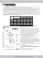
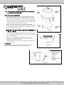
A
REQUIRED CLEARANCE
“B” SIDE
“C” ABOVE
IN
CM
IN
CM
IN
CM
DE2420
32.0
81
18
46
15
38
DE3620
34.1
87
18
46
16
41
DE4820
40.1
102
18
46
18
46
DE6020
46.1
107
18
46
22
56
DE7220
52.0
132
18
46
25
63
DEP60
34.1
87
18
46
16
41
DEP80
40.1
102
18
46
18
46
DEP100
46.1
107
18
46
22
56
INSTALLATION
WARNING
Only simple tools (screwdriver and wrenches), plus pipe sealant for
plastic adapters, are required to install and/or service the filter.
1. The filter system should be installed on a level concrete slab or
other rigid base. Select a well drained and vented area, one that does
not flood when it rains. Position the filter so that the piping
connections, and winter drain are convenient and accessible for
operation, service, maintenance and winterizing.
2. Position filter so the filter will drain by gravity.
3. If practical, place pump and filter in the shade to shield it from
continuous, direct heat from the sun.
4. Assemble appropriate Filter Control valve (See Page 7 for
selection) to filter. Lubricate the O-ring first (we recommend using
Jack’s 327 Lubricant). Align the two (2) valve pipe connections, with
O-rings in place, with the two openings in the side of the filter tank
and press in firmly. Secure the assembly to the tank connections with
the two bulkhead lock nuts. Do not over-tighten.
5. Connect the pool suction plumbing between the skimmer, pool
outlet and the pump.
6. Install the pool return plumbing.
7. If pressure gauge is not installed, apply Teflon tape to the gauge
threads and carefully screw the gauge into the gauge adapter
assembly.
8. Do not locate pump controls over or near filter.
9. Verify water discharge from the filter manual air relief valve is directed away from electrical devices
This product should be installed and serviced only by a
qualified professional.

USE ONLY HAYWARD GENUINE REPLACEMENT PARTS
5
MODEL
EFFECTIVE FILTRATION RATE
DESIGN FLOW RATE
RECOMMENDED AMOUNT OF D.E.
FT
2
M
2
GPM
LPM
LBS
KGS
DE2420
24
2.2
48
182
3.0
1.4
DE3620
36
3.4
72
273
4.5
2.0
DE4820
48
4.5
96
363
6.0
2.7
DE6020
60
5.6
120
454
7.5
3.4
DE7220
72
6.7
144
545
9.0
4.0
DEP60
60
5.6
120
454
6.0
2.7
DEP80
80
7.4
150
568
8.0
3.6
DEP100
100
9.3
150
568
10.0
4.5
MAXIMUM WORKING PRESSURE FOR ALL MODELS 50 PSI (3.45 BAR)
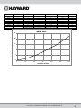
0
5
10
15
20
25
0 25 50 75 100 125 150
Head loss in Feet of Water
Flow Rate in GPM
Head Loss

USE ONLY HAYWARD GENUINE REPLACEMENT PARTS
6
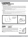
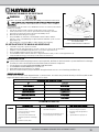
Manual Air Relief Shown Open
In Locked Position
STARTING THE PUMP and FILTER SYSTEM
WARNING
Before Starting the Pump
1. Use ONLY Hayward clamp system components; DEX2421JKIT clamp system, DEX2421J2 nut/bolt assembly, DEX2422Z2
metal reinforced seal. Non-Hayward clamp components may fail in use and cause explosive component separation.
Verify that upper and lower filter bodies are properly secured with the filter body clamp. Never rely on hand tightening
the clamp nut to the clamp bolt. Using a ¾” socket on a torque wrench, torque clamp nut to clamp bolt to 150 inch-lbs.
Verify that the filter manual air relief body is in the LOCK position, and no filter components are missing, damaged or
not genuine Hayward components. (See Fig 2)
2. Close filter drain. Note: Filter plug requires an o-ring seal. (See Fig 4)
3. Open all system valves to allow water from the pool to the filtration system and from the filter to return to the pool.
4. Place the manual air relief valve in OPEN position. (See Fig 2)
Starting Pump
1. When starting system pump, do not stand over or near filter. If water leakage appears at filter tank clamp, immediately
turn off all system circulation pumps and all electrical power. Do not return to the filter until all water leakage has
stopped.
Reassemble the clamp system per the instructions on page 7 in this owner’s manual to stop leak.
2. Return to filter to CLOSE manual air relief valve only when a steady stream of water (not air or, air and water mix) is
discharged from the manual air relief valve.
3. To avoid damages to the filter elements, DO NOT operate the filter for more than a minute or two without the D.E. pre-
coat.
Pre-Coating
Add the correct amount of D.E. (see specifications on the previous page of this manual or on the filter label) into the
system through the skimmer – as fast as the plumbing will take it. Record the pressure gauge reading after the D.E. has
been added. This is the “pre-coat” or “clean” pressure.
OPERATION
WARNING
FILTERING
Filtration starts as soon as the filter has been pre-coated. As the filter removes dirt
from the pool water, the accumulated dirt causes a resistance to flow. As a result,
the gauge pressure will rise and the flow will decrease. When the pressure rises 8-
10 psi (.55-.69 bar) above the pre-coat pressure, it is time to backwash (clean) the
filter. Once your filter is running and there is a pressure reading, line up the green
arrow with the current reading. (See Fig 3) When the pressure rises to or above the
red or second arrow, it is time to clean your filter.
Note: During initial clean-up of the pool, particularly with a new pool or a very dirty
pool, it may be necessary to backwash more frequently due to the heavy initial dirt
load in the water.
CLAMP NUT
CLAMP BOLT
Figure 1
Figure 2
Figure 3
Tighten clamp bolt
and nut using a
torque wrench to
150 inch
-lbs.

USE ONLY HAYWARD GENUINE REPLACEMENT PARTS
7
To prevent unnecessary strain on piping system and valves, always shut off pump before switching Filter
Control Valve positions.
FILTER CONTROL VALVE FUNCTIONS
Six-Position Vari-Flo
TM
Filter Control Valve SP0710XR50 or SP0715XR50
(A) FILTER – Set valve to FILTER for normal filtering. Also use for regular Vacuuming.
(B) BACKWASH –
a. Shut off the pump.
b. Set Filter Control Valve to BACKWASH.
c. Start Pump and backwash approximately two minutes, or until water out waste line appears clean.
d. Shut off pump.
e. Set Control Valve to RINSE.
f. Start pump and operate for 20 seconds.
g. Shut off pump.
h. Set Filter control valve to FILTER.
i. Proceed as in Pre-Coating to add fresh D.E.
(C) RINSE – Water Flows through the filter the same as in FILTER position, except that the water goes to WASTE. An optimal position
used for pre-coating if a large cloud (pre-coat puff) is observed returning to pool during the pre-coating process.
(D) WASTE – To bypass filter for draining or lowering water level and for vacuuming heavy debris directly to WASTE.
(E) RECIRCULATE – Water is re-circulated through the pool system, bypassing the filter.
(F) CLOSED – Shuts off flow from pump to filter.
Four Position Selecta-Flo
TM
Filter Control Valve SP0740DE or SP0425
(A) FILTER– Set valve to FILTER for normal filtering. Also use for regular Vacuuming.
(B) WASTE– To bypass filter for draining or lowering water level and for vacuuming heavy debris directly to WASTE.
(C) BACKWASH–
a. Shut off the pump.
b. Set Filter Control Valve to BACKWASH.
c. Start Pump and backwash approximately two minutes, or until water out waste line appears clean.
d. Shut off pump
e. Set Filter control valve to FILTER.
f. Proceed as in Pre-Coating to add fresh D.E.
(D) POOL OR SPA BOOST - Water is re-circulated through the pool system, bypassing the filter.
Two-Position Slide Valve SP0410X502S
(A) FILTER – Set Valve to FILTER for normal filtering. Also use for vacuuming (Handle in Down position).
(B) BACKWASH –
a. Shut off the pump.
b. Set valve to BACKWASH (UP position).
c. Start Pump and backwash approximately two minutes, or until water out waste line appears clean.
d. Shut off pump
e. Set Filter control valve to FILTER (DOWN Position).
f. Proceed as in Pre-Coating to add fresh D.E. for cleaning filter (Handle in Up position)
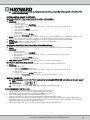
MANUAL CLEANING
Before manually cleaning the filter, backwash by following BACKWASHING instructions under each type of
valve.
WARNING
This product should be installed and serviced only by a qualified professional.
FILTER DISASSEMBLY INSTRUCTIONS
1. Turn off all system circulation pumps and all electric power on the pad.
2. Set all system valves in a position to prevent water flow to the filter.
3. The manual air relief valve must be placed in the OPEN position. (FIG 6)
4. Remove filter drain plug (FIG 4) and drain water from filter.
5. Using 3/4” wrenches, loosen and remove the clamp nut and the clamp bolt. (Fig 5)
6. Holding both ends of the filter body clamp carefully spread the clamp ends. Remove the clamp by lifting over the
upper filter body. Do not to drop the clamp during removal because the clamp could be damaged. Do not strike the
clamp with metal tools as they can damage the clamp.
7. Lift off upper filter body. Do not use the pressure gauge to lift the upper filter body.

USE ONLY HAYWARD GENUINE REPLACEMENT PARTS
8
Figure 6
Manual Air Relief Shown in Open
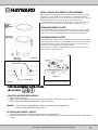
INITIAL CLEANING OF ELEMENT CLUSTER ASSEMBLY
Before removing the element cluster assembly we recommend hosing it
down with a strong stream from a garden hose or preferably with the
Hayward cleaning wand (EC2024). Be sure the drain plug is not in place or
the drain valve is open. Remove as much of the dirty D.E. and
accumulated debris as possible by flushing it out of the drain opening.
This will allow for easier removal of the element cluster assembly.
REMOVING ELEMENT CLUSTER
Rock the element cluster assembly slightly from side to side to free the
manifold from the vertical outlet elbow. The element cluster assembly
may now be removed by lifting it straight up using the lift handles.
CLEANING ELEMENT CLUSTER
The filter element cluster can be cleaned by washing inside and outside
with a garden hose. After hosing filter element cluster, for best results,
carefully brush the surface to remove fine particles. Do Not Pressure
Wash as it can damage the filter element cluster.
You may find some debris on the filter element cluster, which may not
have been removed with hosing.
FILTER RE-ASSEMBLY INSTRUCTIONS
WARNING
CLEAN SEAL RING AND SEAL SURFACE
1. Remove filter tank seal.
2. With a clean cloth wipe the lower filter body seal surface. (Fig 4) Do not use a solvent.
3. With a clean cloth wipe the upper filter body seal surface.
Notice: ∙ Do not use any petroleum solvents to clean filter components.
ࢫ∙ Do not lubricate DEX2422Z2 Seal.
RE-INSTALLING ELEMENT CLUSTER
1. Lubricate outlet elbow O-rings with Jack’s Formula 327 Multilube.
2. Replace filter element cluster into filter tank, carefully fitting top collector manifold outlet over outlet elbow
O-ring.
Clamp Bolt
Clamp Nut
Figure 5
Figure 4

USE ONLY HAYWARD GENUINE REPLACEMENT PARTS
9
Figure 8
Figure 9
Tighten clamp
bolt and nut
using a
torque
wrench to 150
inch-lbs.
WARNING
This product should be installed and serviced only
by a qualified professional.
BODY AND CLAMP RE-ASSEMBLY
1. Place the metal reinforced seal on the lower filter body (Fig 4).
Place the upper filter body on the Hayward DEX2422Z2 metal
reinforced seal and lower filter body in a position which allows
all operation and safety labels to be clearly visible and the upper
body to be centered on the lower filter body. Press down firmly
and evenly to set the upper filter body. (Fig 7)
2. Replace the filter clamp around the upper and lower filter
bodies. Hold the clamp ends to position the clamp on the filter
bodies with the clamp ends adjacent to the safety and operation
labels on the filter bodies. (Fig 7)
DO NOT HIT OR STRIKE CLAMP WITH HAMMER OR
METAL TOOLS.
3. Insert clamp bolt through the clamp ends and thread the clamp
nut onto clamp bolt with rounded end of the nut (Fig 8) towards
the ends of the clamp.
4. Never rely on hand tightening of clamp nut to clamp bolt.
Using a ¾” socket on a torque wrench, torque clamp nut to
clamp bolt to 150 inch-lbs. (Fig 9).
5. Follow Operation Instructions for “Starting the Pump and Filter
System” (Page 5).
VACUUMING
Vacuuming can be performed directly into the filter whenever
needed. Backwash filter after vacuuming, if required.
Clamp Bolt
Clamp Nut
Clamp Bolt
Clamp Nut
Figure 7

USE ONLY HAYWARD GENUINE REPLACEMENT PARTS
10
REMOVING THE MANUAL AIR RELIEF VALVE
WARNING
Your Filter comes with a Manual Air Relief Valve (MAR) pre-installed from the factory.
Only qualified pool professionals should service your filter’s Manual Air
Relief Valve.
For Qualified pool professionals only: If MAR valve needs to be serviced, follow these
instructions carefully.
1. Turn off all system circulation pumps and all electric power on the pad.
2. Set all system valves in a position to prevent water from flowing to the filter.
3. The manual air relief valve must be placed in the OPEN position.
4. Wait until all water leakage has stopped.
5. Grasp the MAR body at the flats, turn the MAR counterclockwise until the
indicator on the on the MAR flange is aligned with the “UNLOCK” position on the
upper filter body.
6. Pull straight up to remove the MAR, a slight rocking motion may help.
RE-INSTALLATION OF THE MANUAL AIR RELIEF VALVE
1. Check the o-ring seals, replace as needed.
2. With a clean cloth, wipe upper filter body and o-ring groove. Remove all dirt and debris.
3. Align the notch in the MAR Flange with notch on top of the upper filter body.
4. Press the MAR straight down into the upper filter body
5. Turn the MAR clockwise until the indicator is aligned with the “LOCK” position on the upper filter body.
6. Verify the MAR discharge points away from all electrical connections.
WINTERIZING FILTER
In areas where subfreezing temperatures can be expected, the filter should be drained to protect the filter from damage.
1. The filter should be disassembled and the filter elements cleaned or replaced.
2. Follow directions under FILTER DISASSEMBLY INSTRUCTIONS
3. Then REMOVE FILTER ELEMENTS per instructions
4. Reassemble per the instructions on Page 8.
5. Be sure to leave the drain plug unattached during the winter season to avoid cracking the filter body.
SERVICE AND REPAIRS
Consult your local authorized Hayward dealer or service center. No returns may be made directly to the factory without the
expressed written authorization of Hayward Pool Products.
SUGGESTED POOL CHEMISTRY LEVELS
pH
7.2 to 7.8
TOTAL ALKALINITY
80 to 120 ppm
CALCIUM HARDNESS
200 to 400 ppm
COMBINED CHLORINE
.2 ppm Maximum
CHLORINE (STABILIZED)
1.0 to 3.0 ppm
CHLORINE STABILIZER
(Cyanuric Acid)
60 to 80 ppm
PROBLEM SOLVING LIST
LOW WATER FLOW
SHORT FILTER CYCLES
POOL WATER WON’T CLEAR UP
REMEDY
1. Check skimmer and pump strainer
baskets for debris.
2. Check for restrictions in intake
and discharge lines.
3. Check for air leak in intake line
(indicated by bubbles returning to
pool).
4. Backwash (Clean) Filter
1. Check for algae in pool and super-
chlorinate as required.
2. Be sure chlorine and pH levels are in
proper range (adjust as required).
1. Check chlorine, pH and total alkalinity
levels and adjust as required.
2. Be sure flow rate through filter is
sufficient.
3. Operate filter for longer periods.
Figure 10
Manual Air Relief Shown Open
In Locked Position
Rotate counterclockwise to UNLOCK

USE ONLY HAYWARD GENUINE REPLACEMENT PARTS
11
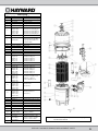
Parts Listing
ITEM
Part No.
Description
1
CCX1000V
Manual Air Relief w/O-ring
2 DEX2420MAR2 Manual Air Relief Assembly
3 ECX2712B1 Pressure Gauge
4 DEX2420Z8A O-Ring Kit (Set of 2)
5
CCX1000N
Manual Air Relief Nut
6
DEX2420BTC
DEX3620BTC
DEX4820BTC
DEX6020BTC
DEX7220BTC
Filter Head w/Clamp DE2420
Filter Head w/Clamp DE3620
Filter Head w/Clamp DE4820
Filter Head w/Clamp DE6020
Filter Head w/Clamp DE7220
7 (28)
DEX2420LA6PAK
Label Pack*
8 DEX2421JKIT
Clamp System including:
Clamp, Clamp nut and Bolt,
Hang tag, Metal Reinforced
Seal and Labels
9
DEX2421J2
Clamp Bolt and Nut
10 DEX2420LA6PAK Label Pack*
11
DEX2422Z2
Metal Reinforced Seal
12 ECX176865 Retainer Nut 5/16”-18
13
ECX1109
Washer (2 Required)
14 DEX2400C Top Collector Manifold
15
DEX2400R
DEX3600R
DEX4800R
DEX6000R
DEX7200R
Retainer Rod DE2420
Retainer Rod DE3620
Retainer Rod DE4820
Retainer Rod DE6020
Retainer Rod DE7220
16
DEX2400CR
Flex Air Relief Assembly
17
DEX2400Z5
Outlet Elbow O-ring
18
DEX2420EA
DEX3620EA
DEX4820EA
DEX6020EA
DEX7220EA
Outlet Elbow DE2420
Outlet Elbow DE3620
Outlet Elbow DE4820
Outlet Elbow DE6020
Outlet Elbow DE7220
19
DEX2420DC
DEX3600DC
DEX4800DC
DEX6000DC
DEX7200DC
Filter Element Cluster
Assembly (Complete set of
elements, collectors,
Locators, Manifold, ect.
20
DEX2400DA
DEX3600DA
DEX4800DA
DEX6000DA
DEX7200DA
Filter Element
(7 Required)
21
DEX2400DS
DEX3600DS
DEX4800DS
DEX6000DS
DEX7200DS
Filter Element Short
(1 Required)
22 DEX2420GA Inlet Diffuser
23 DEX2420T Element Spacer (DE2420 Only)
24 DEX2400H Filter Element Locator
25
SX220Z2
Bulkhead O-Ring (2 Req.)
26 DEX2420F Bulkhead Fitting (2 Req.)
27
DEX2420ATC
Filter Body w/Clamp
29 SP1022C 1 ½” Drain Plug w/ O-Ring
30 DEX2420DCKIT
Strap Kit (Optional)
2 straps, 2 Screws
31
SX200Z4
O-Ring (2 Req.)
32
SP0740DE
SP0710XR50
SP0715XR50
Selecta-Flo Valve 2” SKT
Vari-Flo Valve 1 ½” NPT
Vari-Flo Valve 2” NPT
33 SP0410X5025 Slide Valve 2” SKT
*Label Pack: Includes all Warning and Operation Labels, Hang Tag, Wire
Tie and Owner’s Manual

USE ONLY HAYWARD GENUINE REPLACEMENT PARTS
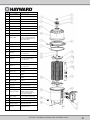
12
ITEM
PART NUMBER
DESCRIPTION
1 ECX2712B1 Pressure Gage
2 DEX2420Z8A O-Ring Kit (Set of 2)
3 CCX1000N Air Relief Valve Nut
4 CCX1000V Manual Air Relief w/O-Ring
5 DEX2420MAR2 Manual Air Relief Assembly
6a DEX3620BTC Upper Filter Body DEP60
6b DEX4820BTC Upper FIlter Body DEP80
6c DEX6020BTC Upper Filter Body DEP100
7 DEX2421J2 Clamp Bolt & Nut
8 DEX2421JKIT
Clamp System Including:
Clamp, Clamp Nut and Bolt,
Hang Tag, Metal Reinforced
Seal, and Labels
9 DEX2422Z2 Metal Reinforced Seal
10 CX3030C Top Manifold
11 CX3000J1 Air Relief Filter
12 CX2030Z3 Air Relief Tube
13a DEX150E
Cartridge Element DEP60
1 of 4 Required
DEX150EPAK4 Cartridge 4 Pack DEP60
13b DEX200E
Cartridge Element DEP80
1 of 4 Required
DEX200EPAK4 Cartridge 4 Pack DEP80
13c DEX250E
Cartridge Element DEP100
1 of 4 Required
DEX250EPAK4 Cartridge 4 Pack DEP100
14 DEX2400Z5 O-Ring
15a DEX6040EA
Outlet Elbow Assembly
DEP60
15b DEX8040EA
Outlet Elbow Assembly
DEP80
15c DEX10040EA
Outlet Elbow Assembly
DEP100
16 CX3020FB Inlet Elbow
17 CX3030D Bottom Seal Plate
18 DEX2420ATC Lower Filter Body
19 DEX6040LA6PAK
Label Pack: Includes all
Warning and Operation
Labels, Hang Tag, Wire Tie,
and Owner's Manual
20 SP1022CBLK 1 1/2" Drain Plug w/O-Ring
21 SX220Z2 O-Ring
22 DEX2420F Bulkhead Fitting
23 DEX2420DCKIT Strap Kit (Optional)
24 SP0425 SelectaFlo Valve

USE ONLY HAYWARD GENUINE REPLACEMENT PARTS
13
HAYWARD LIMITED WARRANTY
To buyer, as original purchaser of this equipment, Hayward Pool Products, 620 Division Street, Elizabeth, New Jersey, warrants its products to be
free from defects in materials and workmanship for a period of (see below) from the date of purchase.
Parts which fail or become defective during the warranty period, except as a result of freezing, negligence, improper installation, use, or care,
shall be repaired or replaced, at our option, without charge, within 90 days of the receipt of defective product, barring unforeseen delays.
To obtain warranty replacements or repair, defective components or parts should be returned, transportation paid, to the place of purchase, or to
the nearest authorized Hayward service center. For further Hayward dealer or service center information, contact Hayward customer service
department. No returns may be made directly to the factory without the express written authorization of Hayward pool Products.
To original purchasers of this equipment, Hayward Pool Products warrants its products to be free from defects in materials and workmanship for a
period of (see below) from the date of purchase.
Filters which become defective during the warranty period, except as a result of freezing, negligence, improper installation, use or care, shall be
repaired or replaced, at our option, without charge,
All other conditions and terms of the standard warranty apply.
Hayward shall not be responsible for cartage, removal and/or reinstallation labor or any other such costs incurred in obtaining warranty
replacements.
The Hayward Pool Products warranty does not apply to components manufactured by others. For such products, the warranty established by the
respective manufacturer will apply.
Some states do not allow a limitation on how long an implied warranty lasts, or the exclusion or limitation of incidental or consequential
damages, so the above limitation or exclusion may not apply to you.
This warranty gives you specific legal rights, and you may also have other rights, which vary from state to state.
Product Line
Warranty Period
Standard Line
One (1) year
Expert line
Two (2) years
Hayward pool Products
620 Division Street
*Supersedes all previous publications. Elizabeth, NJ 07207

USE ONLY HAYWARD GENUINE REPLACEMENT PARTS
14
PRODUCT REGISTRATION
(Retain For Your Records)
DATE OF INSTALLATION ____________________
▲Retain this Warranty Certificate (upper portion) in a safe and convenient location for your records.
Hayward and ProGrid are registered trademarks of Hayward
Industries, Inc.
Please Print Clearly:
First Name____________________ Last Name_________________________
Street Address__________________________________________________
City_____________________________ State___________ Zip____________
Phone Number_____________________ Purchase Date_________________
E-Mail Address__________________________________________________
Serial Number
Model Number_____________________________________________________
Pool Capacity_______________(U.S. Gallons)
If your product contains components that have individual serial numbers, it is not
necessary to complete warranty registration for those individual components.
Instead, complete warranty registration only for the overall product, using the
serial number that is located on the outside of the product packaging.
Please include me on all e-mail communications regarding Hayward
Equipment or promotions.
Mail to: Hayward Pool Products, 620 Division Street, Elizabeth, NJ 07207
Attn: Warranty Dept
Or REGISTER YOUR WARRANTY ON-LINE AT WWW.HAYWARD.COM
DETACH HERE: Fill out bottom portion completely and mail within 10 days of purchase/installation or register online.
-------------------------------------------------------------------------------------------------------------------------------------------------
D.E. Filter Warranty Card Registration
Register online at www.hayward.com
Years Pool has been in service
< 1 year 1-3 4-5 6-10 11-15 >15
Purchased from_____________________________
Builder Retailer Pool Service Internet/Catalog
Company Name_________________________________
Address_______________________________________
City____________________ State_____ Zip__________
Phone_________________________________________
Type of Pool:
Concrete/Gunite Vinyl Fiberglass
Other_____________________________
New Installation Replacement
Installation for:
In Ground Above Ground Spa
-
 1
1
-
 2
2
-
 3
3
-
 4
4
-
 5
5
-
 6
6
-
 7
7
-
 8
8
-
 9
9
-
 10
10
-
 11
11
-
 12
12
-
 13
13
-
 14
14


Hayward DEP80 Owner's manual
- Category
- Above ground pool accessories
- Type
- Owner's manual
- This manual is also suitable for
Ask a question and I''ll find the answer in the document
Finding information in a document is now easier with AI
Related papers
-
Hayward Pro-Grid™ Vertical Grid Owner's manual
-
Hayward Super Pump® High Efficiency High Efficiency Owner's manual
-
Hayward IS3200XE Owner's manual
-
Hayward W3SP3210X15XE User manual
-
Hayward PRO GRID C9002SEP Owner's manual
-
Hayward RC9740WCCUB Owner's manual
-
-
-
Hayward Pro & VL Series : S180T Owner's manual
-
Other documents
-
A.O. Smith AO-MF Installation guide
-
Troy-Bilt 23AAHAAX711 Fast Start Guide
-
Blue Wave NE636 User manual
-
Pentair P1-717 User manual
-
-
 Hayward Pool Products PRO Series Owner's manual
-
-
Pentair S8D110 User manual
-
Pentair FullFloXF User guide
-
Espa 199398 Operating instructions
