KitchenAid 6899551 User manual

Category
Cooker hoods
Type
User manual

This manual is also suitable for

Product dimensions
1 1 Cabinet dimensions I
)2) Venting requirements
Electrical reauirements
I
I3 I I4
I
Installation steos
I
The KitchenAid Consumer Assistance Center:
The KitchenAid Consumer Assistance Center is open 24 hours a day,
7 days a week. Call l-(800) 422-1230. (The call is free within the
continental United States.)
Call the KitchenAid Consumer Assistance Center when you:
q
Have questions about range hood installation or operation.
q
Need to obtain the name and number of a KitchenAid-authorized
service company.
When you call, you will need:
q
The range hood model number.
q
The range hood serial number.
Both numbers are listed on the serial/rating plate, locatkd %side the
range hood on the rear wall.
Important: Observe all governing codes
and ordinances.
Proper installation is your responsibility:
l
Have a qualified technician install this range hood.
l
Comply with installation clearances specified on the
serial/rating plate.
Serial/rating plate is located inside the range hood on
rear wall.
Range hood location should be away from strong draft
areas, such as windows, doors and strong heating vents.
Cabinet opening dimensions that are shown must be
used. Given dimensions provide minimum clearance.
Consult your cook-top/range manufacturer installation
instructions before making any cutouts.
Grounded electrical outlet is required. See “Electrical
requirements.”
Ductwork must terminate outdoors.
All openings in wall where range hood will be installed
must be sealed.
0” min. - 20” max.
upper
chimney height
t
22”
lower
chimney height
\
g-112” Lanopy
height
I
Electrical Shock Hazard
It is the customer’s responsibility:
l
To contact a qualified electrical installer.
l
To assure that the electrical installation is
adequate and in conformance with National
Electrical Code, ANSVNFPA 70 - latest edition*,
and all local codes and ordinances.
Failure to do so could result in fire, electrical shock
or other personal injury.
Electrical Shock Hazard
l
Take special care cutting holes into wall. Electrical
wires may be concealed behind the wall covering
and contact with them could result in electrical
shock.
l
Locate any electrical circuits that could be affected
by the installation of this product and disconnect
power circuit.
Failure to do so could result in fire, electrical shock
or other personal injury.
Personal Injury Hazard
Reaching over a heated cooking surface should be
avoided. To reduce the hazard of being burned, the
range hood should extend a minimum of 5 inches
out from the bottom of the cabinet.
Reaching over a heated cooking surface could result
in a serious burn.
19” between top
mounting bracket
and middle
mounting bracket
$
Tools needed:
34-518” min.
between
‘-‘I
cooking
surface and
-.c___---
35 /,i~~k--&sJ-
<rail upper cabinet
24” min. bottom
h
13” -
cabinet
depth
- l-1/4” drill bit
opening width
18” min. clearance
upper cabinet to
7’ 7-112” min. -
9’ 3-l/2”
max.
ceiling to floor
5
d
saw
flat-blade
screwdrive
ruler
- 6’
*
wire stripper
or utility knife
Parts needed:
screwdriver
2 U-L.-listed, l/2” conduit
connectors
power supply cable
wall or roof cap
wiring cable
(only with remote blower)
metal ductwork
Parts supplied:
fl
ZZet
0
36”
base
cabinet
height
0
=#=
4
screws
Mobile home installation
The installation of range hood must conform to the
Manufactured Home Construction and Safety Standards,
Title 24 CFR, Part 3280 (formerly the Federal Standard
for Mobile Home Construction and Safety, Title 24, HUD
Part 280); or when such standard is not applicable, the
Standard for Manufactured Home Installation 1982
(Manufactured Home Sites, Communities and Setups),
ANSI A225.VNFPA 501A, or with local codes.
Four-wire power supply must be used and the appliance
wiring must be revised. See “Electrical requirements.”
Copies of the standards listed may be obtained from:
+ National Fire Protection Association
Batterymarch Park
Quincy, Massachusetts 02269
** Note: If canopy is mounted
higher than 24” above cooking
surface, upper chimney may
need to be cut. See Page 4.
Page 1
Fire Hazard
l
Terminate venting system to outside.
l
Do Not terminate the vent in an attic or other
enclosed space.
l
Use only metal ductwork.
l
Do Not use 4” laundry-type wall caps.
~
l
Do Not obstruct the flow of combustion and
ventilation air.
Failure to follow these instructions could result in a fire.
Property Damage
l
Before making cutouts, make sure there is proper
clearance within the wall or floor for the exhaust duct.
l
Do Not cut a joist or stud unless absolutely necessary.
If a joist or stud must be cut, then a supporting frame
must be constructed.
Failure to follow these instructions may result in
property damage.
For the most efficient and quiet operation:
q
The size of the ductwork should be uniform.
q
Use no more than three 90” elbows.
q
The length of ductwork and number of elbows
should be kept to a minimum to provide efficient
performance.
q
Make sure there is a minimum of 24 inches of
straight duct between the elbows if more than one
elbow is used.
q
Do Not install two elbows together.
q
Ducting should transition to 9’ round duct as soon
as possible.
q
9’ round ducting is recommended for remote
blowers.
q
If roof or wall cap has a damper, Do Not use
damper supplied with the range hood.
q
Use duct tape to seal all joints in the ductwork
system.
q
Use caulking to seal exterior wall or roof
opening around the cap.
Determine which venting method is best for your
application and follow “Installation steps” starting
on Page 4.
Venting methods
This range hood can be installed as either ducted or
ductless.
Ductwork needed for installation is not included.
3-l/4” x IO” rectangular, 7” round, 8” round or 9” round
ducting may be used.
Ductwork can terminate either through the roof or wall.
To vent through a wall, a 90” elbow is needed.
The ductwork length should not exceed the lengths
shown in the chart below.
Vertical roof venting
Horizontal wall venting
Duct size
Maximum length
3-l/4’ x 10’
35 feet
7’ round
40 feet
8’ round
50 feet
9’ round
60 feet
Ductless installations vent out the grates in the sides of
the chimney. Ductless installations require a Ductless
Installation Kit, (Part Nos: 4378620 almond,
4378621 stainless steel,
4378622 white),
available from your
KitchenAid dealer.
Calculating the
ductwork length
To calculate the length of the system you need, add the
equivalent feet for each ductwork piece used in the system.
Ductwork Piece
3-W’ x 10” Rectangular
7”, 8” or 9” Round
3-l/4” x 10” ductwork system
45” elbow
90” elbow
90” flat elbow
7.0 feet .$s ::....
..&!:;;.. 3-l/4” x
.A...::::..:.
2.5 feet ...sssky.
62
~~:+.:‘.~:::.
.: _
10” elbow
..:...-
. ..&f
>.., .::::..
..::::::::::::::*z
s:., ..:::,
. . . . . . . . . . . . ...<.
,:2$7
-.- . . . . . . . . . .
w wall cap
5.0 feet
.$:....
. . . . . . . ..>A
5.0 feet
..:::z:..
..<::::<<::*:p
.:~::<~;:y.”
I
..;.:.:.:..... ;:..
“1 -‘I
@
‘. .:a::::..
;:.
s:.::;.
_.<.’ ./A:.:
i &A::::::::::;;;
-:I@
.:.-.- ::.
F
. . . . . ..- . . . . .
,,:~.~~:~~~:~~~~:::.:~
:....... . . . . .
.-....... I
,.:.:.:.:.:..
2 ft.
Maximum length
= 35 feet
12.0 feet
1 - 90” elbow = 5ft.
::...>::;
;gz:i .,., ‘.:: ..:.,
. . . . . .
:~~~~~~~~
8 feet straight
= 8ft.
:.~.~~~::~::.:.. ‘X
:,::::+.~;g$$
-1
. . . . . . . . . . . . . . . . . .
1 -wall cap
= oft.
_
Length of
transition to round
wall cap
5.0 feet
;;.;..
,.. . . . . .
,-.- --.>>:.>:
. . . . . . . .
. . . . . .
. . . .
-=o
..:.. _ i -
.-.
:..............
_
. . . . . .
0.0 feet ,&+
~~~~ .g$<
@
. . . . . . . . . . . .
‘; ..;’
.:::::::::::::::::::::,
. . . . . . . . . . . . . . .
_
-.
3-l/4’ x 10’ system
= 13ft.
Note: Flexible ductwork is Not recommended.
If it is used, each foot of flexible ductwork used is
equivalent to two feet of straight metal ductwork
when calculating the ductwork length.
(Example:
A flexible elbow equals two standard elbows.)
Page 2
Power cable opening
1. Determine and clearly mark a vertical centerline
on the wall in the area where the range hood will
be installed.
2. Mark a line 7-3/4’ from the right side of the
centerline. Mark a line where the bottom of the
range hood will be. From this line measure
up 4-7/16’. Drill a l-1/4’ diameter hole through
the wall at this point.
Electrical Shock Hazard
l
Electrical ground is required on this
appliance.
l
Do Not ground to a gas pipe.
l
Do Not have a fuse in the neutral or
grounding circuit. A fuse in the neutral or
grounding circuit could result in electrical
shock.
l
Check with a qualified electrician if you are in
doubt as to whether the appliance is properly
grounded.
Failure to follow these instructions could result
in serious injury or death.
Electrical Shock Hazard
Care must be taken when drilling holes into
wall. Electrical wires may be concealed behind
the wall covering.
Failure to do so could result in fire, electrical
shock or other personal injury.
4-l/16”
between center
of power
supply
cable
opening and
w-m--
mmwmmmm
i----- ---
7-314” +
between centerline
f
of cabinet opening
and center of power
cable opening
/
I
j-
I
i
If codes permit and a separate grounding wire is
used, it is recommended that a qualified electrician
determine that the grounding path is adequate.
q
A 120~volt, 60-Hz, AC-only, fused electrical
supply is required on a separate 15-amp circuit,
fused on both sides of the line.
q
A time-delay fuse or circuit breaker is
recommended.
q
CONNECT WITH COPPER WIRE ONLY.
q
Connect directly to the fused disconnect (or
circuit breaker box) through flexible, armored or
non-metallic sheathed, copper cable (with
grounding wire).
q
A U.L.-listed conduit connector must be used at
each end of the power supply cable.
q
Allow some slack in the cable so appliance can
be moved if servicing is ever necessary.
Wire sizes (COPPER ONLY) must conform with the
rating of the appliance, as specified on the
serial/rating plate, and to the requirements of the
National Electrical Code, ANSVNFPA 70 - latest
edition (* Page II, and all local codes and
ordinances.
Wiring diagram is shown on the back cover of
these instructions.
- 13” min. -
-7
24” min.
-i
35-318” -
18”
min.
Preparation
install ductwork
to canopy
Property Damage
l
Cover countertop, cooktop or range with a
thick, protective covering.
l
Before making cutouts, make sure there is
proper clearance within the wall or floor for
the exhaust duct.
l
Do Not cut a joist or stud unless absolutely
necessary. If a joist or stud must be cut,
then a supporting frame must be
constructed.
l
Slide cardboard or hardboard under range
before moving range across floor.
Failure to follow these instructions may
result in property damage.
attach upper
chimney to top
bracket first
bracket 4
middle
secure
chimney pieces
with screws
adjustment
screws
I I
1
Disconnect and move freestanding range
n
from cabinet opening. Put a thick,
protective covering over countertop, cooktop or
range to protect from damage or dirt.
2
Determine and mark the centerline on the
n
wall where range hood will be installed.
Determine and mark the location of the bottom
edge of the range hood canopy (24’ min. from
cooking surface) on the wall where range hood
will be installed.
Note: If a backsplash (Part No. 4378615 stainless
steel only) is to be used with range hood, install it
according to the manufacturer’s instructions
before installing the range hood. The backsplash
height will determine the position of the bottom
edge of the range hood canopy.
attach lower
chimney to
+ middle bracket
bottom
bracket
hood will be on wall
I
filters
Page 3
Attachment
bracket ; ; ;
to ceiling 1
I
I
I
I
I
I
I
I
I
I :
+z&
I I
I
I
I
I
I
I
I
I
l/8"
top
middle
bracket
I
34-518” min.
I
24” min.
3.
The range hood chimney adjusts to meet varying
ceiling heights from 8 feet to 9 feet. Determine and
mark the location of the chimney mounting brackets:
l
Top bracket: l/8’ from the ceiling.
l
Bottom bracket: IO-5/8’ above bottom edge of
range hood canopy.
l
Middle bracket: At the bottom edge of the upper
chimney sleeve.
Note: If canopy is mounted more than 24 inches
above countertop, it may be necessary to cut the
upper chimney sleeve. Use great care not to damage
or bend upper chimney sleeve when cutting.
4
Install the top and middle brackets with ends
n
touching wall and curves facing out. Install
bottom bracket with metal flanges on the bottom.
Check that brackets are securely fastened to wall.
5
Determine and make all necessary cuts in
n
wall or ceiling for ductwork. Install ductwork.
(See “Venting requirements” section, Page 2.)
6
Disconnect power supply. Run wiring
n
through wall or cabinets according to
National Electrical Code and local codes and
ordinances. Do Not turn on power until installation
is completed.
AI
/
w Press on handle in front of filters to release
filters from range hood canopy. Remove filters and
set aside.
8
Remove the terminal box cover from the
n
range hood. Remove the power supply
cable knockout using a flat-blade screwdriver.
Personal Injury Hazard
Because of the weight and size of the range
hood canopy, two or more people are needed
to move and safely install the range hood
canopy.
Failure to properly lift range hood could result
in damage to the product or personal injury.
9
Rotate the two adjustment screws halfway
n
into slots. Hang canopy from flange of lower
bracket, making sure that tabs are fully inserted in
slots and canopy is secure on bracket. Adjust the
height of the canopy by rotating the two screws.
Attach conduit connector to power supply cable
opening so that conduit connector clamping screws
are on inside of range hood. Feed enough power
supply cable through conduit connector to make
electrical connections.
10
Check that canopy is level. If needed,
n
turn adjusting screws until canopy is level.
Electrical connection
Electrical Shock Hazard
l
Electrical ground is required on this appliance.
9 Do Not connect to the electrical supply until
the appliance is permanently grounded.
l
Disconnect power to the junction box before
making the electrical connection.
l
This appliance must be connected to a
grounded, metallic, permanent wiring system,
or a grounding connector should be connected
to the grounding terminal or wire lead on the
appliance.
Failure to do so could result in a fire, personal
injury or electrical shock.
11
n
Make electrical connection:
q
Connect the power supply cable to range hood
terminal box through the U.L.-listed conduit
connector.
l7J Connect the white wire of the power supply
cable with the white lead in the range hood,
using a twist-on connector; connect the black
wire of the power supply cable with the black
lead in the range hood, using a twist-on
connector.
0 Connect the power supply green (green and
yellow) grounding wire under the green,
grounding screw.
l7J Tighten conduit connector screws.
i7J Replace the terminal box cover.
Install chimney
sections
12
Attach damper to exhaust opening on
n
top of canopy using two Phillips-head
screws. Connect ductwork to damper and seal all
connections with duct tape.
13
Position upper chimney on top and middle
Place filters in canopy opening so rear
n
brackets. Slide lower chimney over upper
14
n
edge is over flange. Press filters up
chimney. Slide lower chimney down onto lower
into position.
bracket and canopy for a snug fit. Then secure
chimney pieces to brackets with screws provided.
Check operation
15
n
Turn power on.
I
-.. _
-5zaiz~>~>
control panel = =--.-
location
16
The range hood controls are located in a
n
grey panel on the underside of the
canopy. To open the panel, press up on front edge
of panel and release. The control panel will drop
down.
I
I
“IQ I-la@ -l-o
I
c 3: 0 1
QO1
--mm1
light switch
blower switch
blower speed switch
17
n
Check the operation of the range hood:
q
Move light switch to “1” position. The light
should turn on.
q
Move the blower switch to “1” position. The
blower should operate.
q
Move the blower speed switch to the far left;
blower speed should be LOW. Move blower
speed to right, blower speed should gradually
increase until you reach HIGH speed at far right.
q
Move blower and light switches to “0” position
to turn blower and light off.
If range hood does not operate:
q
Check that the circuit breaker is not tripped or
the house fuse blown.
To get the most efficient use
from your new range hood, read the
“Use and Care Information” section.
Keep your KitchenAid Installation
Instructions and Use and Care Guide
close to range hood for easy reference.
Page
4
Grease Fire Hazard
To reduce the risk of a range top grease fire:
l
Keep fan, filters and grease-laden surfaces
clean.
l
Always turn hood ON when cooking at high
heat.
l
Only use high heat setting on range when
necessary.
l
Use low to medium setting to heat oil.
l
Never leave range unattended when
cooking.
l
Always use cookware and utensils
appropriate to the type and amount of food
being prepared.
In the event of a grease fire:
l
Smother flames with a tight-fitting lid,
cookie sheet or metal tray. Then turn off the
element/burner.
l
Evacuate and call the fire department if the
flames do not go out immediately.
l
Never pick up a flaming pan. You could be
seriously burned.
l
Do Not extinguish flames with water, wet
dishcloths or towels. Water creates a violent
steam explosion that could cause serious
burns.
l
ONLY use a fire extinguisher if:
1. It is a Class ABC extinguisher and you
know how to use it.
2. The fire is small and contained in the area
where it started.
3. You have called the fire department.
4. You can fight the fire with your back to
an exit.
Failure to take these precautions could lead to
serious personal injury or death.
Electrical Shock Hazard
l
Use range hood only in the manner intended
by the manufacturer. If you have questions
about its use, contact the KitchenAid
Consumer Assistance Center.
l
Disconnect power at service panel and lock
service panel before servicing or cleaning
unit.
l
If any electrical problem becomes evident
during use, disconnect power to range hood
at fuse or circuit breaker box.
Failure to follow these instructions could
result in electrical shock or fire.
Operation
The range hood is designed to remove smoke,
cooking vapors and odors from the cook-top area.
For best results, start the range hood before
cooking and allow it to operate several minutes
after the cooking is complete to clear all smoke and
odors from the kitchen.
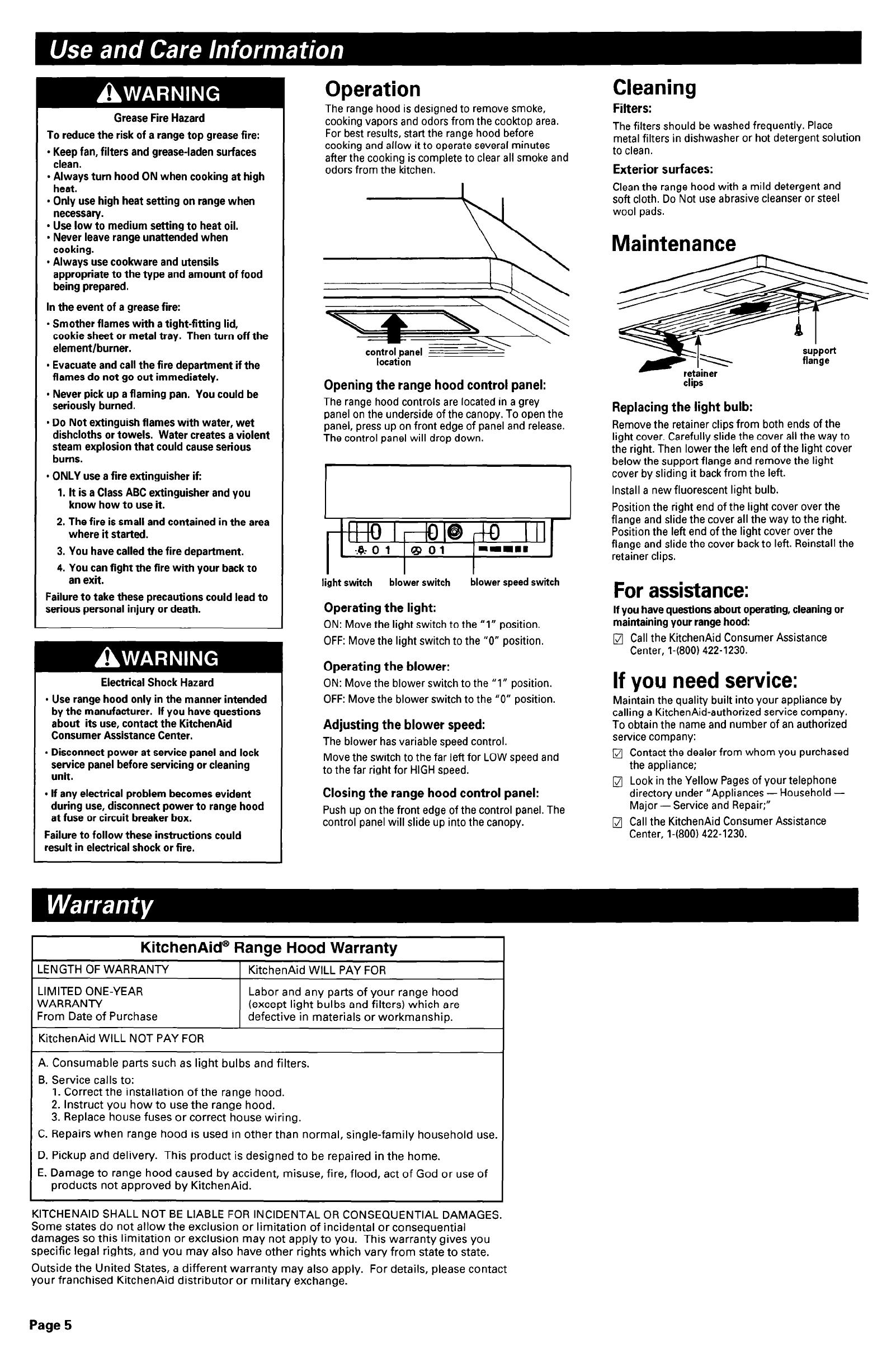
location
Opening the range hood control panel:
The range hood controls are located in a grey
panel on the underside of the canopy. To open the
panel, press up on front edge of panel and release.
The control panel will drop down.
light switch
blower switch
blower speed switch
Operating the light:
ON: Move the light switch to the “1” position.
OFF: Move the light switch to the “0” position.
Operating the blower:
ON: Move the blower switch to the “1” position.
OFF: Move the blower switch to the “0” position.
Adjusting the blower speed:
The blower has variable speed control.
Move the switch to the far left for LOW speed and
to the far right for HIGH speed.
Closing the range hood control panel:
Push up on the front edge of the control panel. The
control panel will slide up into the canopy.
I
KitchenAid@ Range Hood Warranty
1 LENGTH OF WARRANTY
1 KitchenAid WILL PAY FOR
LIMITED ONE-YEAR
WARRANT-Y
From Date of Purchase
Labor and any parts of your range hood
(except light bulbs and filters) which are
defective in materials or workmanship.
~ KitchenAid WILL NOT PAY FOR
A. Consumable parts such as light bulbs and filters.
B. Service calls to:
1. Correct the installation of the range hood.
2. Instruct you how to use the range hood.
3. Replace house fuses or correct house wiring.
C. Repairs when range hood is used in other than normal, single-family household use.
D. Pickup and delivery. This product is designed to be repaired in the home.
E. Damage to range hood caused by accident, misuse, fire, flood, act of God or use of
products not approved by KitchenAid.
1
1
Cleaning
Filters:
The filters should be washed frequently. Place
metal filters in dishwasher or hot detergent solution
to clean.
Exterior surfaces:
Clean the range hood with a mild detergent and
soft cloth. Do Not use abrasive cleanser or steel
wool pads.
Maintenance
clips
Replacing the light bulb:
Remove the retainer clips from both ends of the
light cover. Carefully slide the cover all the way to
the right. Then lower the left end of the light cover
below the support flange and remove the light
cover by sliding it back from the left.
Install a new fluorescent light bulb.
Position the right end of the light cover over the
flange and slide the cover all the way to the right.
Position the left end of the light cover over the
flange and slide the cover back to left. Reinstall the
retainer clips.
For assistance:
If you have questions about operating, cleaning or
maintaining your range hood:
q
Call the KitchenAid Consumer Assistance
Center, l-(800) 422-1230.
If you need service:
Maintain the quality built into your appliance by
calling a KitchenAid-authorized service company.
To obtain the name and number of an authorized
service company:
q
Contact the dealer from whom you purchased
the appliance;
q
Look in the Yellow Pages of your telephone
directory under “Appliances - Household -
Major - Service and Repair;”
q
Call the KitchenAid Consumer Assistance
Center, l-(800) 422-1230.
KITCHENAID SHALL NOT BE LIABLE FOR INCIDENTAL OR CONSEQUENTIAL DAMAGES.
Some states do not allow the exclusion or limitation of incidental or consequential
damages so this limitation or exclusion may not apply to you. This warranty gives you
specific legal rights, and you may also have other rights which vary from state to state.
Outside the United States, a different warranty may also apply. For details, please contact
your franchised KitchenAid distributor or military exchange.
Page 5
Internal blower
Backsplash:
Wire Racks:
Rack Hanger Kits:
I
6b’I
I
I
I
I
000
i
I
I Utensil Bars:
I
I
---
I
L------
.-------
--------
ii
583
mom
Charcoal Filters:
(2 per pkg.)
Ductless Venting Kits:
&; .
2;
is:
II
FLUORESCENT LRnP
r---
-----------
-- --I
11
I I
BLOWER tlOTOR
I
I---___
11
L--------------,
LINE IN 2
128 WAC 3
60HZ
Note: Instructions are included with each kit.
Part No. 4378615
(stainless steel only) must be
installed before hood is installed.
Part No. 4378616
(chrome only)
Part No. 4378617
(chrome only)
Part No. 4378618
35-3/8’ (90 cm) long
(stainless steel only)
Part No. 4378619
15’ (38 cm) long
(stainless steel only).
Part No. 4378623
Part No. 4378620
(almond)
Part No. 4378621
(stainless steel)
Part No. 4378622
(white)
KEltchenAhB”
Part No. 68995511883297
HOME APPLIANCES
0 1994 KitchenAid
8 KitchenAid Registered Trademark of KitchenAid.
Prepared by KitchenAid, St. Joseph, Michigan 49085
Printed on recycled paper.
10% post consumer waste/
50% recovered materials
Printed in U.S.A.
  • Page 1 1
  • Page 2 2
  • Page 3 3
  • Page 4 4
  • Page 5 5
  • Page 6 6
  • Page 7 7

KitchenAid 6899551 User manual

Category
Cooker hoods
Type
User manual
This manual is also suitable for

Ask a question and I''ll find the answer in the document

Finding information in a document is now easier with AI