Harbor Freight Tools 33615 Owner's manual
- Category
- Power tools
- Type
- Owner's manual
This manual is also suitable for

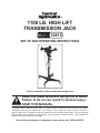
1100 LB. HIGH LIFT
TRANSMISSION JACK
33615
SET UP AND OPERATING INSTRUCTIONS
Visit our website at: http://www.harborfreight.com
Read this material before using this product.
Failure to do so can result in serious injury.
SAVE THIS MANUAL.
Copyright
©
2009 by Harbor Freight Tools
®
. All rights reserved. No portion of this manual or any artwork
contained herein may be reproduced in any shape or form without the express written consent of
Harbor Freight Tools. Diagrams within this manual may not be drawn proportionally. Due to continuing
improvements, actual product may differ slightly from the product described herein. Tools required for
assembly and service may not be included.
For technical questions or replacement parts, please call 1-800-444-3353.

Page 2 For technical questions, please call 1-800-444-3353. SKU 33615
SAVE THIS MANUAL
Keep this manual for the safety
warnings and precautions, assembly,
operating, inspection, maintenance and
cleaning procedures. Write the product’s
serial number in the back of the manual
near the assembly diagram (or month
and year of purchase if product has no
number). Keep this manual and the
receipt in a safe and dry place for future
reference.
Safety Alert Symbol and Signal
Words
In this manual, on the labeling,
and all other information
provided with this product:
This is the safety alert
symbol. It is used to alert
you to potential personal
injury hazards. Obey all
safety messages that
follow this symbol to avoid
possible injury or death.
DANGER indicates
a hazardous
situation which, if not
avoided, will result in death or
serious injury.
WARNING
indicates a
hazardous situation which, if
not avoided, could result in
death or serious injury.
CAUTION, used
with the safety
alert symbol, indicates a
hazardous situation which, if
not avoided, could result in
minor or moderate injury.
NOTICE is used to
address practices
not related to personal injury.
CAUTION, without
the safety alert
symbol, is used to address
practices not related to
personal injury.
IMPORTANT SAFETY
INSTRUCTIONS
INSTRUCTIONS PERTAINING
TO A RISK OF FIRE,
ELECTRIC SHOCK, OR
INJURY TO PERSONS
WARNING – When using tools, basic
precautions should always be
followed, including the following:
General
a. To reduce the risks of electric
shock, re, and injury to persons,
read all the instructions before
using the tool.
Work area
a. Keep the work area clean and well
lighted. Cluttered benches and dark
areas increase the risks of electric
shock, re, and injury to persons.
b. Keep bystanders, children, and
visitors away while operating the
tool. Distractions are able to result in
the loss of control of the tool.
Personal safety
a. Stay alert. Watch what you are
doing and use common sense

Page 3For technical questions, please call 1-800-444-3353.SKU 33615
when operating the tool. Do not
use the tool while tired or under
the inuence of drugs, alcohol, or
medication. A moment of inattention
while operating the tool increases the
risk of injury to persons.
b. Dress properly. Do not wear loose
clothing or jewelry. Contain long
hair. Keep hair, clothing, and
gloves away from moving parts.
Loose clothes, jewelry, or long hair
increases the risk of injury to persons
as a result of being caught in moving
parts.
c. Do not overreach. Keep proper
footing and balance at all times.
Proper footing and balance
enables better control of the tool in
unexpected situations.
d. Use safety equipment. A
dust mask, non-skid safety
shoes and a hard hat must
be used for the applicable
conditions. Wear heavy-duty work
gloves during use.
e. Always wear eye
protection. Wear ANSI-
approved safety goggles.
Tool use and care
a. Do not force the tool. Use the
correct tool for the application. The
correct tool will do the job better and
safer at the rate for which the tool is
designed.
b. Disconnect the tool from the
air source before making
any adjustments, changing
accessories, or storing the tool.
Such preventive safety measures
reduce the risk of starting the tool
unintentionally. Turn off and detach
the air supply, safely discharge any
residual air pressure, and release the
throttle and/or turn the switch to its off
position before leaving the work area.
c. Store the tool when it is idle out
of reach of children and other
untrained persons. A tool is
dangerous in the hands of untrained
users.
d. Maintain the tool with care. Keep
a cutting tool sharp and clean. A
properly maintained tool, with sharp
cutting edges reduces the risk of
binding and is easier to control.
e. Check for misalignment or binding
of moving parts, breakage of
parts, and any other condition
that affects the tool’s operation.
If damaged, have the tool serviced
before using. Many accidents are
caused by poorly maintained tools.
There is a risk of bursting if the tool is
damaged.
f. Use only accessories that are
identied by the manufacturer for
the specic tool model. Use of an
accessory not intended for use with
the specic tool model, increases the
risk of injury to persons.
Service
a. Tool service must be performed
only by qualied repair personnel.
b. When servicing a tool, use only
identical replacement parts. Use
only authorized parts.
c. Use only the lubricants supplied
with the tool or specied by the
manufacturer.

Page 4 For technical questions, please call 1-800-444-3353. SKU 33615
SAVE THESE
INSTRUCTIONS.
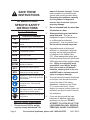
SYMBOLS AND
SPECIFIC SAFETY
INSTRUCTIONS
Symbol Denitions
Symbol Property or statement
n
o
No-load speed
.../min
Revolutions or reciprocation per
minute
PSI
Pounds per square inch of pressure
ft-lb
Foot-pounds of torque
BPM
Blows per minute
CFM
Cubic Feet per Minute ow
SCFM
Cubic Feet per Minute ow at
standard conditions
NPT
National pipe thread, tapered
NPS
National pipe thread, straight
WARNING marking concerning Risk
of Eye Injury. Wear ANSI-approved
eye protection.
WARNING marking concerning Risk
of Hearing Loss. Wear hearing
protection.
WARNING marking concerning Risk
of Respiratory Injury. Wear NIOSH-
approved dust mask/respirator.
WARNING marking concerning Risk
of Explosion.
Specic Safety Instructions
1. Do not exceed 1100 lb. weight
capacity evenly distributed. Be
aware of dynamic loading! Sudden
load movement may briey create
excess load causing product failure.
Exceeding the maximum capacity
for this product is dangerous
and can lead to serious injury or
property damage.
2. Do not suspend load for more than
30 minutes at a time.
3. Always evaluate your task before
using this jack. This jack is
designed to support a transmission
or a differential as individual
components. Use as intended only.
Do not use for aircraft purposes.
4. Assemblies such as differential
with axle, or transmission with bell
housing, can be bulky and difcult
to balance on the Saddle Plate
(72). Wear appropriate safety gear,
including heavy-duty work gloves and
ANSI-approved safety goggles during
use. Lifting or supporting such
assemblies, even within weight
limit, can create an off-balance
situation, causing Jack to tip over
and MAY lead to serious personal
injury or property damage.
5. The load should be evenly distributed
on the jack, and should not extend
beyond the area of the castor
wheelbase. Always use the Chain
(71) to secure the load. If extra
support is required, safety straps (not
included) can also be used to secure
the workpiece.
6. If you are working and the load
becomes off-balance and/or the
jack begins to tip over, DO NOT
ATTEMPT TO CATCH OR LIFT THE
LOAD WHEN FALLING. SERIOUS
PERSONAL INJURY CAN RESULT!

Page 5For technical questions, please call 1-800-444-3353.SKU 33615
In this event, clear the area as
quickly and safely as possible in
order to avoid injury from the falling
load, including getting hit with ying
fragments.
7. If in doubt about the safety of your
project, we advise you to have
the work done by a professional
familiar with applicable safety
practices.
8. Use only on a hard, level and at
surface capable of bearing the
combined weight of the Transmission
Jack, the load being lifted, the
operator and any tools being used.
9. The Legs (43) are on Casters (48).
Make sure the casters are blocked
before use.
10. The Transmission Jack is not
designed to lift or lower a vehicle.
Suspend the vehicle with an in-oor
hydraulic jack (not included.)
11. The warnings and precautions
discussed in this manual cannot
cover all possible conditions and
situations that may occur. It must
be understood by the operator that
common sense and caution are
factors which cannot be built into this
product, but must be supplied by the
operator.
12. Obey the manual for the air
compressor used to power this tool.
13. Install an in-line shutoff valve to allow
immediate control over the air supply
in an emergency, even if a hose is
ruptured.
SAVE THESE
INSTRUCTIONS.
FUNCTIONAL DESCRIPTION
Specications
Weight Capacity 1100 lb.
Lift Range 44-3/4” - 70-3/4”
Saddle Tilt 30°
Safety Chain 4’ L x 3/16” Diameter
INITIAL TOOL SET UP/
ASSEMBLY
Read the ENTIRE IMPORTANT
SAFETY INFORMATION
section at the beginning of this
manual including all text under
subheadings therein before set
up or use of this product.
Note: For additional information regarding
the parts listed in the following pages,
refer to the Assembly Diagram near
the end of this manual.
Unpacking
When unpacking, make sure that the
item is intact and undamaged. If any parts
are missing or broken, please call Harbor
Freight Tools at 1-800-444-3353 as soon
as possible.
NOTE: After unpacking, remove the
Shipping Plug (14) from the side of the Oil
Reservoir (17) and replace it with the Air
Vent Valve (15).
ASSEMBLY
1. To assemble the bottom of the unit,
line up the holes on the Pump Base
(42) with the holes on each Leg
Assembly (43). Fasten the Leg
to Pump Base using the Spring
Washers (46) and Bolts (47). Repeat

Page 6 For technical questions, please call 1-800-444-3353. SKU 33615
on the other side. See Assembly
Diagram on back of manual for
reference.
2. Slide each Caster (48) up into a Leg.
Fasten together using Spring Washer
(45) and Nut (44).
3. To assemble top unit, remove
Retaining Ring (74) from Front Shaft
(73) and insert Front Shaft through
Saddle Plate (72). Replace Retaining
Ring, locking Front Shaft in Saddle
Plate.
4. Remove Pin (84) and Nut (83) from
Screw Rod (77). Slide off Washer
(82) and Bearings (78). NOTE:
When replacing Bearings, do not
insert them upside down. The
grooved faces should be towards the
Ball Rack.
5. Thread Screw Rod through Screw
Rod Shaft (80). Slide one Bearing
onto Screw Rod and insert Screw
Rod through Rear Pivot Pin (81).
Fasten in place using Bearing (78),
Washer (82), Nut (83) and Pin (84).
6. Fasten the Angle Brackets (68) to top
of Saddle Plate using Bolts (69), Nuts
(66) and Washers (67).
7. Attach Corner Plates (64) to Angle
Brackets using Bolts (69), Washers
(67) and Nuts (66). NOTE: Do not
tighten completely in case you need
to adjust spacing.
8. Attach Bar (61) to one Corner Plate
using Washer (62) and Nut (65).
Attach end link of Chain (71) to
opposite Corner Plate using Bolt (70)
and Washer (62).
9. Slide Saddle Base onto top of
Cylnder Head (3). Attach using the
Screw (86).
OPERATING INSTRUCTIONS
Read the ENTIRE IMPORTANT
SAFETY INFORMATION
section at the beginning of this
manual including all text under
subheadings therein before set
up or use of this product.
Inspect tool before use, looking
for damaged, loose, and
missing parts. If any problems
are found, do not use tool until
repaired.
Tool Set Up
TO PREVENT
SERIOUS INJURY
FROM ACCIDENTAL
OPERATION: Remove load
and lower Transmission Jack
before performing any
inspection, maintenance, or
cleaning procedures.
TO PREVENT SERIOUS
INJURY: Do not adjust or
tamper with any control or
component in a way not
specically explained within
this manual. Improper
adjustment can result in
tool failure or other serious
hazards.
General Operating Instructions
1. Designate a work area that is clean
and well-lit. The work area must not
allow access by children or pets to
prevent distraction and injury.

Page 7For technical questions, please call 1-800-444-3353.SKU 33615
2. Prior to initial use, jack up the Saddle
and, using the Release Knob (9),
attempt to lower it. Doing so will
familiarize the use with the control
functions and Jack, if needed.
3. Once the vehicle is safely and
properly secured on an in-oor
jack (not included), position the
Transmission Jack underneath your
vehicle.
4. Pump the Pedal (38) to raise the Jack
to contact and bear transmission
weight. After making contact with the
transmission, make sure it is centered
within the two brackets on the Saddle
Plate (72). Use Adjustment Knob
(75) to position Saddle Base (85).
5. After contact, lift the Jack another
inch to transfer the weight of the
transmission from the vehicle chassis
to the Transmission Jack.
6. Unscrew transmission. With
assistance, remove transmission
bolts freeing it from the vehicle.
Making sure there is nothing
to restrict the movement of the
transmission.
7. Back off transmission to free from
engine.
8. Check the Saddle; make sure it is
securely holding the transmission
and not showing any signs of stress.
Carefully lower it by turning the
Release Knob (9).
9. Again check the Saddle Plate;
making sure it is securely holding the
transmission and not showing any
signs of stress.
10. Secure the Chain (71) tightly over
the transmission and safely move the
Transmission Jack.
11. After removal, lower the Jack to the
lowest possible point. Warning! The
Jack is designed to lift loads only for
short periods of time. Do not use
to suspend a load for more than 30
minutes at a time.
12. To re-mount the transmission, reverse
this procedure.
Bleeding Instructions
If the Transmission Jack is not
working properly, it may be due to trapped
air in the hydraulic system, and would
require bleeding as described below.
1. Unscrew the Air Vent Valve (15) on
the back side of the Oil Reservoir
(17).
2. Back off the spring-loaded Release
Knob (9).
3. Allow Saddle to retract fully. Pump
the Pump Pedal (38) at least ten
times to bleed all air from the system.
4. Top off with clean hydraulic uid.
5. Replace and tighten the Air Vent
Valve.
6. Close the release valve and test the
unit.

Page 8 For technical questions, please call 1-800-444-3353. SKU 33615
INSPECTION, MAINTENANCE,
AND CLEANING
Procedures not specically
explained in this manual
must be performed only by a
qualied technician.
TO PREVENT
SERIOUS INJURY
FROM TOOL FAILURE:
Do not use damaged
equipment. If abnormal noise
or vibration occurs, have the
problem corrected before
further use.
1. Before each use, inspect the general
condition of the Transmission Jack.
Check for oil leaks, jack operation,
loose components, free rotation
and pivoting of saddle adjustment
components. If a problem occurs,
have the problem corrected before
further use.
Do not use damaged equipment.
2. Before each use, thoroughly test
the Transmission Jack for proper
operation prior to its actual use.
If the Jack appears not to be
working properly, follow Bleeding
instructions on page 7.
3. Change the hydraulic oil at least
once every three years:
a. With the Jack fully lowered, remove
the Air Vent Valve at the top edge of
the Cylinder Barrel (17).
b. Tip the Jack to allow the old
hydraulic oil to drain out of the
Housing completely, and dispose of
the old hydraulic oil in accordance
with local regulations.
c. With the Jack upright, completely ll
the Housing with a fresh hydraulic
Jack oil (not included) until the oil
just begins to run out of the Oil Fill
Hole.
d. Perform bleeding procedures under
“Bleeding Instructions.”
4. Clean with a clean cloth with a
detergent or mild solvent. Then,
store the Jack in a safe, dry location
out of reach of children and other
non-authorized people.

Page 9For technical questions, please call 1-800-444-3353.SKU 33615
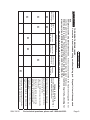
Troubleshooting
TO PREVENT SERIOUS INJURY:
Use caution when troubleshooting a malfunctioning jack. Stay well clear of the supported
load.
Completely resolve all problems before use. If the solutions presented in the Troubleshooting guide do not
solve the problem, have a qualied technician inspect and repair the jack before use.
After the jack is repaired: Test it carefully without a load by raising it and lowering it fully, checking for
proper operation, BEFORE RETURNING THE JACK TO OPERATION.
DO NOT USE A DAMAGED OR MALFUNCTIONING JACK!
POSSIBLE SYMPTOMS
PROBABLE SOLUTION
(Make certain that the jack is not supporting a
load while attempting a solution.)
Jack will not
lift at its weight
capacity
Saddle
lowers under
load
Pump stroke
feels spongy
Saddle will not
lift all the way
Handle moves
up when jack
is under load
Oil leaking
from ller plug
X X
Check that Air Vent Valve is closed fully.
X X X
Valves may be blocked and may not close
fully. To ush the valves:
1. Lower the Saddle and securely close the
Air Vent Valve.
2. Manually lift the saddle several inches.
3. Open the Air Vent Valve and force the
saddle down as quickly as possible.
X
X X
Jack may be low on oil. Check the oil level
and rell if needed.
Jack may require bleeding - see instructions
on page 7.
X
Unit may have too much hydraulic oil inside,
check uid level and adjust if needed.

Page 10 For technical questions, please call 1-800-444-3353. SKU 33615
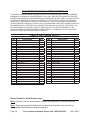
Part Description Q’ty
1 Dust Seal 30 1
2 O-Ring 35 x 3.1 2
3 Cylinder Head Assembly 1
4 Steel Ball 1/4" 2
5 O-Ring 15 x 2.4 1
6 Release Rod 1
7 Bushing 1
8 Spring 1
9 Release Knob 1
10 Set Screw M5 x 8 1
11 Spring Pin 4 x 20 1
12 O-Ring 45 x 3.1 1
13 O-Ring 60 x 3.1 2
14 Shipping Plug 2
15 Air Vent Valve 1
16 O-Ring 12 x 1.9 3
17 Oil Reservoir 1
18 Cylinder 2
19 Ram Assembly 1
20 O-Ring 36.5 x 1.8 1
21 Screw 1
22 Steel Ball 9.5 1
23 Retaining Ring 16 1
24 Washer 16 1
25 Bushing 1
Part Description Q’ty
26 Spring 1
27 Dust Seal 16 1
28 O-Ring 20 x 2.4 1
29 Piston Housing 1
30 Pump Piston 1
31 U-Cup Seal 16 x 8 x 6 1
32 O-Ring 22 x 2.4 1
33 Screw 1
34 Spring 1
35 Taper Valve 1
36 Retaining Ring 12 1
37 Bushing 1
38 Pump Pedal 1
39 Washer 12 1
40 Washer 10 1
41 Lock Nut M10 1
42 Pump Base Assembly 1
43 Leg Assembly 2
44 Nut M12 4
45 Spring Washer 12 4
46 Spring Washer 10 4
47 Bolt M10 x 20 4
48 Caster Assembly 4
49 Screw 1
PLEASE READ THE FOLLOWING CAREFULLY
THE MANUFACTURER AND/OR DISTRIBUTOR HAS PROVIDED THE PARTS LIST AND ASSEMBLY
DIAGRAM IN THIS MANUAL AS A REFERENCE TOOL ONLY. NEITHER THE MANUFACTURER OR
DISTRIBUTOR MAKES ANY REPRESENTATION OR WARRANTY OF ANY KIND TO THE BUYER THAT
HE OR SHE IS QUALIFIED TO MAKE ANY REPAIRS TO THE PRODUCT, OR THAT HE OR SHE IS
QUALIFIED TO REPLACE ANY PARTS OF THE PRODUCT. IN FACT, THE MANUFACTURER AND/
OR DISTRIBUTOR EXPRESSLY STATES THAT ALL REPAIRS AND PARTS REPLACEMENTS SHOULD
BE UNDERTAKEN BY CERTIFIED AND LICENSED TECHNICIANS, AND NOT BY THE BUYER. THE
BUYER ASSUMES ALL RISK AND LIABILITY ARISING OUT OF HIS OR HER REPAIRS TO THE
ORIGINAL PRODUCT OR REPLACEMENT PARTS THERETO, OR ARISING OUT OF HIS OR HER
INSTALLATION OF REPLACEMENT PARTS THERETO.
PARTS LIST (MAIN BODY)
Record Product’s Serial Number Here:
Note: If product has no serial number, record month and year of purchase instead.
Note: Some parts are listed and shown for illustration purposes only, and are not
available individually as replacement parts.

Page 11For technical questions, please call 1-800-444-3353.SKU 33615
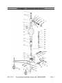
ASSEMBLY DIAGRAM (MAIN BODY)
49

Page 12 For technical questions, please call 1-800-444-3353. SKU 33615
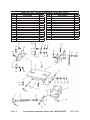
Part Description Q’ty
60 Tension Screw 1
61 Bar 1
62 Washer 8 3
63 Fly Nut M8 1
64 Corner Plate 4
65 Nut M8 2
66 Nut M10 6
67 Washer 10 6
68 Angle Bracket 6
69 Bolt (M10 x 1.5 x 25) )2
70 Bolt (M8 x 1.25 x 25) 1
71 Chain 1
72 Saddle Plate 1
73 Front Pivot Pin 1
Part Description Q’ty
74 Retaining Ring 16 2
75 Adjustment Knob 1
76 Spring Pin 4 x 24 1
77 Spindle 1
78 Bearing 2
79 Retaining Ring 30 4
80 Screw Rod Shaft 1
81 Rear Pivot Pin 1
82 Washer 12 1
83 Castle Nut M10 1
84 Split Pin 2.5 x 25 1
85 Bracket 1
86 Screw (M8 x 1.25 x 10) 1
PARTS LIST AND DIAGRAM (UPPER UNIT)
64 67
66
69
69

Page 13For technical questions, please call 1-800-444-3353.SKU 33615
90 Day Warranty
Harbor Freight Tools Co. makes every effort to assure that its products meet high quality
and durability standards, and warrants to the original purchaser that this product is free
from defects in materials and workmanship for the period of 90 days from the date of
purchase. This warranty does not apply to damage due directly or indirectly, to misuse,
abuse, negligence or accidents, repairs or alterations outside our facilities, criminal
activity, improper installation, normal wear and tear, or to lack of maintenance. We
shall in no event be liable for death, injuries to persons or property, or for incidental,
contingent, special or consequential damages arising from the use of our product.
Some states do not allow the exclusion or limitation of incidental or consequential
damages, so the above limitation of exclusion may not apply to you. THIS WARRANTY
IS EXPRESSLY IN LIEU OF ALL OTHER WARRANTIES, EXPRESS OR IMPLIED,
INCLUDING THE WARRANTIES OF MERCHANTABILITY AND FITNESS.
To take advantage of this warranty, the product or part must be returned to us with
transportation charges prepaid. Proof of purchase date and an explanation of the
complaint must accompany the merchandise. If our inspection veries the defect, we
will either repair or replace the product at our election or we may elect to refund the
purchase price if we cannot readily and quickly provide you with a replacement. We will
return repaired products at our expense, but if we determine there is no defect, or that
the defect resulted from causes not within the scope of our warranty, then you must
bear the cost of returning the product.
This warranty gives you specic legal rights and you may also have other rights which
vary from state to state.
3491 Mission Oaks Blvd. • PO Box 6009 • Camarillo, CA 93011 • (800) 444-3353
-
 1
1
-
 2
2
-
 3
3
-
 4
4
-
 5
5
-
 6
6
-
 7
7
-
 8
8
-
 9
9
-
 10
10
-
 11
11
-
 12
12
-
 13
13


Harbor Freight Tools 33615 Owner's manual
- Category
- Power tools
- Type
- Owner's manual
- This manual is also suitable for
Ask a question and I''ll find the answer in the document
Finding information in a document is now easier with AI
Related papers
-
Harbor Freight Tools 93376 User manual
-
Pittsburgh Automotive 800 lb. Low Lift Transmission Jack Owner's manual
-
-
-
-
-
-
-
-
Central Hydraulics Item 36396 User manual
Other documents
-
Power Fist 8667909 Owner's manual
-
OTC 1794A Owner's manual
-
Pittsburgh Automotive 60240 Owner's manual
-
Central Hydraulics 42820 Operating Instructions Manual
-
-
MAC TOOLS JSTT1000 Owner's manual
-
Ranger RTJ-1 Owner's manual
-
-
-