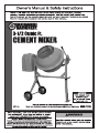
Harbor Freight Tools 3_1/2 Cubic Ft. Cement Mixer Owner's manual
- Category
- Power tools
- Type
- Owner's manual
This manual is also suitable for


Page 2 For technical questions, please call 1-888-866-5797. Item 61932
NOTICE
FOR CEMENT AND MORTAR ONLY.
Do not use with Epoxy 2-part resin mix.
SAFETY OPERATION MAINTENANCESETUP
NOTICE
FOR CEMENT AND MORTAR ONLY.
Do not use with Epoxy 2-part resin mix.
Table of Contents
Safety ......................................................... 3
Specifications ............................................. 6
Setup .......................................................... 7
Operation ................................................... 10
Maintenance .............................................. 12
Parts List and Diagram .............................. 14
Warranty .................................................... 16
WARNING SYMBOLS AND DEFINITIONS
This is the safety alert symbol. It is used to alert you to potential
personal injury hazards. Obey all safety messages that
follow this symbol to avoid possible injury or death.
Indicates a hazardous situation which, if not avoided,
will result in death or serious injury.
Indicates a hazardous situation which, if not avoided,
could result in death or serious injury.
Indicates a hazardous situation which, if not avoided,
could result in minor or moderate injury.
Addresses practices not related to personal injury.

Page 3For technical questions, please call 1-888-866-5797.Item 61932
NOTICE
FOR CEMENT AND MORTAR ONLY.
Do not use with Epoxy 2-part resin mix.
SAFETYOPERATIONMAINTENANCE SETUP
NOTICE
FOR CEMENT AND MORTAR ONLY.
Do not use with Epoxy 2-part resin mix.
IMPORTANT SAFETY INFORMATION
WARNING Read all safety warnings and instructions. Failure to follow the warnings and instructions
may result in electric shock, fire and/or serious injury.
Save all warnings and instructions for future reference.
Assembly Precautions
1. Assemble only according to these instructions.
Improper assembly can create hazards.
2. Wear ANSI-approved safety goggles and
heavy-duty work gloves during assembly.
3. Keep assembly area clean and well lit.
4. Keep bystanders out of the area during assembly.
5. Do not assemble when tired or when under the
influence of alcohol, drugs or medication.
6. Weight capacity and other product capabilities apply
to properly and completely assembled product only.
Use Precautions
1. This product is not a toy. Do not allow
children to play with or near this item.
2. Use as intended only.
3. Inspect before every use; do not use
if parts are loose or damaged.
4. Do not exceed listed weight capacity.
Be aware of dynamic loading!
Sudden load movement may briefly create
excess load causing product failure.
5. DO NOT OVERLOAD MIXER. An
overload can damage equipment.
6. DO NOT MOVE MIXER DURING OPERATION.
The Mixer can tip over or motor could be damaged.
7. KEEP SAFE CLEARANCE AROUND MIXER.
Keep all persons (except operator) at least
six feet from Mixer during operation.
8. DON’T USE IN DANGEROUS ENVIRONMENT.
Don’t use power tools in damp or wet locations, or
expose them to rain. Keep work area well lighted.
9. KEEP CHILDREN AWAY. All visitors should
be kept safe distance from work area.
10. MAKE WORKSHOP KID PROOF with padlocks,
master switches, or by removing starter keys.
11. DON’T FORCE TOOL. It will do the job better
and safer at the rate for which it was designed.
12. USE RIGHT TOOL. Don’t force tool or attachment
to do a job for which it was not designed.
13. USE PROPER EXTENSION CORD. Make sure
your extension cord is in good condition. When
using an extension cord, be sure to use one
heavy enough to carry the current your product
will draw. An undersized cord will cause a drop
in line voltage resulting in loss of power and
overheating. Table A shows the correct size to use
depending on cord length and nameplate ampere
rating. If in doubt, use the next heavier gauge. The
smaller the gauge number, the heavier the cord.
14. WEAR PROPER APPAREL. Do not wear loose
clothing, gloves, neckties, rings, bracelets, or
other jewelry which may get caught in moving
parts. Nonslip footwear is recommended. Wear
protective hair covering to contain long hair.
15. SECURE WORK. Use clamps or a vise to hold
work when practical. It’s safer than using your
hand and it frees both hands to operate tool.
16. DON’T OVERREACH. Keep proper
footing and balance at all times.
17. MAINTAIN TOOLS WITH CARE. Keep
tools sharp and clean for best and safest
performance. Follow instructions for
lubricating and changing accessories.
18. DISCONNECT TOOLS before servicing;
when changing accessories, such as
blades, bits, cutters, and the like.
19. REDUCE THE RISK OF UNINTENTIONAL
STARTING. Make sure switch is in
off position before plugging in.
20. NEVER STAND ON TOOL. Serious injury
could occur if the tool is tipped or if the
cutting tool is unintentionally contacted.
21. NEVER LEAVE TOOL RUNNING
UNATTENDED. TURN POWER OFF. Don’t
leave tool until it comes to a complete stop.
22. Maintain product labels and nameplates.
These carry important safety information.
If unreadable or missing, contact
Harbor Freight Tools for a replacement.

Page 4 For technical questions, please call 1-888-866-5797. Item 61932
NOTICE
FOR CEMENT AND MORTAR ONLY.
Do not use with Epoxy 2-part resin mix.
SAFETY OPERATION MAINTENANCESETUP
NOTICE
FOR CEMENT AND MORTAR ONLY.
Do not use with Epoxy 2-part resin mix.
Grounding
TO PREVENT ELECTRIC SHOCK AND DEATH FROM
INCORRECT GROUNDING WIRE CONNECTION:
Check with a qualified electrician if you are in doubt as to whether the outlet is properly
grounded. Do not modify the power cord plug provided with the tool. Never remove the
grounding prong from the plug. Do not use the tool if the power cord or plug is damaged. If damaged, have
it repaired by a service facility before use. If the plug will not fit the outlet, have a proper outlet installed by
a qualified electrician.
Grounded Tools: Tools with Three Prong Plugs
3-Prong Plug and Outlet
1. Tools marked with “Grounding Required” have
a three wire cord and three prong grounding
plug. The plug must be connected to a properly
grounded outlet. If the tool should electrically
malfunction or break down, grounding provides
a low resistance path to carry electricity away
from the user, reducing the risk of electric
shock. (See 3-Prong Plug and Outlet.)
2. The grounding prong in the plug is connected
through the green wire inside the cord to the
grounding system in the tool. The green wire
in the cord must be the only wire connected
to the tool’s grounding system and must
never be attached to an electrically “live”
terminal. (See 3-Prong Plug and Outlet.)
3. The tool must be plugged into an appropriate outlet,
properly installed and grounded in accordance
with all codes and ordinances. The plug and outlet
should look like those in the preceding illustration.
(See 3-Prong Plug and Outlet.)
Extension Cords
1. Grounded tools require a three wire extension cord.
Double Insulated tools can use either
a two or three wire extension cord.
2. As the distance from the supply outlet increases,
you must use a heavier gauge extension cord.
Using extension cords with inadequately sized wire
causes a serious drop in voltage, resulting in loss of
power and possible tool damage. (See Table A.)
3. The smaller the gauge number of the wire, the
greater the capacity of the cord. For example,
a 14 gauge cord can carry a higher current
than a 16 gauge cord. (See Table A.)
4. When using more than one extension cord
to make up the total length, make sure
each cord contains at least the minimum
wire size required. (See Table A.)
5. If you are using one extension cord for more
than one tool, add the nameplate amperes
and use the sum to determine the required
minimum cord size. (See Table A.)
6. If you are using an extension cord outdoors, make
sure it is marked with the suffix “W-A” (“W” in
Canada) to indicate it is acceptable for outdoor use.
7. Make sure the extension cord is properly wired
and in good electrical condition. Always replace
a damaged extension cord or have it repaired
by a qualified electrician before using it.
8. Protect the extension cords from sharp objects,
excessive heat, and damp or wet areas.

Page 5For technical questions, please call 1-888-866-5797.Item 61932
NOTICE
FOR CEMENT AND MORTAR ONLY.
Do not use with Epoxy 2-part resin mix.
SAFETYOPERATIONMAINTENANCE SETUP
NOTICE
FOR CEMENT AND MORTAR ONLY.
Do not use with Epoxy 2-part resin mix.
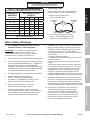
TABLE A: RECOMMENDED MINIMUM WIRE
GAUGE FOR EXTENSION CORDS* (120/240 VOLT)
NAMEPLATE
AMPERES
(at full load)
EXTENSION CORD
LENGTH
25´ 50´ 75´ 100´ 150´
0 – 2.0 18 18 18 18 16
2.1 – 3.4 18 18 18 16 14
3.5 – 5.0 18 18 16 14 12
5.1 – 7.0 18 16 14 12 12
7.1 – 12.0 18 14 12 10 -
12.1 – 16.0 14 12 10 - -
16.1 – 20.0 12 10 - - -
* Based on limiting the line voltage drop to five volts at
150% of the rated amperes.
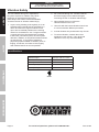
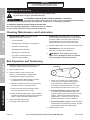
Connecting Cords
To reduce the risk of the cords pulling apart
during operation, do one of the following:
a. Make a knot as shown below
then connect the cords:
b.
Extension
Cord
Appliance
Cord
1
2
Or, use a plug-receptacle retaining
strap or connector designed to hold
extension cords to appliance cords.
Mixer Safety Warnings
1. FOR CEMENT AND MORTAR ONLY. DO NOT
USE WITH EPOXY 2-PART RESIN MIX.
WARNING! Do not attempt to move the Cement
Mixer when it is full and/or in operation. It is
unsafe to move the mixer while in this condition,
and severe injury to personnel could occur.
2. When servicing use only identical replacement parts.
3. Only use safety equipment that has been approved
by an appropriate standards agency. Unapproved
safety equipment may not provide adequate
protection. Eye protection must be ANSI-approved
and breathing protection must be NIOSH-approved
for the specific hazards in the work area.
4. Industrial applications must follow OSHA guidelines.
5. Maintain labels and nameplates on
the tool. These carry important safety
information. If unreadable or missing, contact
Harbor Freight Tools for a replacement.
6. Avoid unintentional starting. Prepare to
begin work before turning on the tool.
7. People with pacemakers should consult their
physician(s) before use. Electromagnetic fields in
close proximity to heart pacemaker could cause
pacemaker interference or pacemaker failure.
8. WARNING: Some dust created by power sanding,
sawing, grinding, drilling, and other construction
activities, contains chemicals known [to the State
of California] to cause cancer, birth defects or
other reproductive harm. Some examples of these
chemicals are:
• Lead from lead-based paints
• Crystalline silica from bricks and cement or other
masonry products
• Arsenic and chromium from chemically treated
lumber
Your risk from these exposures varies, depending
on how often you do this type of work. To reduce
your exposure to these chemicals: work in a well
ventilated area, and work with approved safety
equipment, such as those dust masks that are
specially designed to filter out microscopic particles.
(California Health & Safety Code § 25249.5, et seq.)
9. WARNING: Handling the cord on this product will
expose you to lead, a chemical known to the State
of California to cause cancer, and birth defects or
other reproductive harm. Wash hands after handling.
(California Health & Safety Code § 25249.5, et seq.)
10. The warnings, precautions, and instructions
discussed in this instruction manual cannot
cover all possible conditions and situations
that may occur. It must be understood by the
operator that common sense and caution are
factors which cannot be built into this product,
but must be supplied by the operator.

Page 6 For technical questions, please call 1-888-866-5797. Item 61932
NOTICE
FOR CEMENT AND MORTAR ONLY.
Do not use with Epoxy 2-part resin mix.
SAFETY OPERATION MAINTENANCESETUP
NOTICE
FOR CEMENT AND MORTAR ONLY.
Do not use with Epoxy 2-part resin mix.
Vibration Safety
This tool vibrates during use. Repeated or
long-term exposure to vibration may cause
temporary or permanent physical injury,
particularly to the hands, arms and shoulders.
To reduce the risk of vibration-related injury:
1. Anyone using vibrating tools regularly or for an
extended period should first be examined by a
doctor and then have regular medical check-
ups to ensure medical problems are not being
caused or worsened from use. Pregnant women
or people who have impaired blood circulation
to the hand, past hand injuries, nervous system
disorders, diabetes, or Raynaud’s Disease should
not use this tool. If you feel any medical or
physical symptoms related to vibration (such as
tingling, numbness, and white or blue fingers),
seek medical advice as soon as possible.
2. Do not smoke during use. Nicotine reduces
the blood supply to the hands and fingers,
increasing the risk of vibration-related injury.
3. Wear suitable gloves to reduce the
vibration effects on the user.
4. Use tools with the lowest vibration when there
is a choice between different processes.
5. Include vibration-free periods each day of work.
6. To reduce vibration, maintain the tool as
explained in this manual. If any abnormal
vibration occurs, stop use immediately.
Specifications
Electrical Input 120 VAC / 60 Hz / 3.5 A
Motor No Load Speed 1820 RPM
Drum Speed 36 RPM
Drum Capacity 3-1/2 Cubic Feet
Drum Opening 15"
227541

Page 7For technical questions, please call 1-888-866-5797.Item 61932
NOTICE
FOR CEMENT AND MORTAR ONLY.
Do not use with Epoxy 2-part resin mix.
SAFETYOPERATIONMAINTENANCE SETUP
Setup - Before Use
Read the ENTIRE IMPORTANT SAFETY INFORMATION section at the beginning of this document
including all text under subheadings therein before set up or use of this product.
TO PREVENT SERIOUS INJURY FROM ACCIDENTAL OPERATION:
Turn the Power Switch of the tool off before performing any procedure in this section.
Note: For additional information regarding the parts listed in the following pages,
refer to the Assembly Diagram near the end of this manual.
Assembly/Mounting
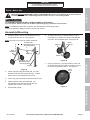
1. Place the Stand (78) into the Wheel Bracket (4)
so that bolt holes line up. See Figure A.
Note: Set Stand on its side for easier assembly.
Hex Bolts (70),
Flat Washer (55),
Hex Flange Nut (5)
Wheel
Bracket (4)
Leg (79)
Stand (78)
Hex Bolts (69),
Flat Washer (55),
Hex Flange Nut (5)
Figure A
2. Fasten together using Hex Bolts (69, 70), Flat
Washers (55) and Hex Flange Nuts (5). Tighten
with a wrench (not included) until secure.
3. Insert Leg (79) into Stand so that bolt holes line up.
4. Fasten together using Hex Bolts (69, 70),
Flat Washers (55) and Hex Flange Nuts (5).
Tighten with a wrench until secure.
5. Place Stand upright.
6. To attach Wheels (3) to Wheel Bracket, slide a
Flat Washer (2), Wheel and second Flat Washer
onto each end of Bracket axle. See Figure B.
Wheel
Bracket (4)
Wheel (3)
Flat
Washer (2)
Figure B
7. Insert a Cotter Pin (1) through holes in each end
of the Bracket axle and bend the Cotter Pins over
to secure the Wheels in place. See Figure C.
Cotter
Pin (1)
Figure C

Page 8 For technical questions, please call 1-888-866-5797. Item 61932
NOTICE
FOR CEMENT AND MORTAR ONLY.
Do not use with Epoxy 2-part resin mix.
SAFETY OPERATION MAINTENANCESETUP
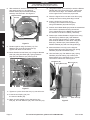
8. With assistance, set the Lower Drum (48)
with attached Arm (77) and Support
Bracket Seats (35) into Stand assembly
and align the bolt holes. See Figure D.
Lower Drum (48)
Support Bracket
Seat (35)
Arm (77)
Figure D
9. Fasten together using Hex Bolts (71), Flat
Washers (55), and Hex Flange Nuts (5).
Tighten with wrench until secure.
10. Mount Handle Control Plate (41) to Support Bracket
Seat (35) using Hex Bolts (28), Spring Washers
(29) and Flat Washers (30). See Figure E.
Handle Control Plate (41)
Hex Bolt (28),
Washers
(29 & 30)
Arm (77)
Flat Washers (45)
Hex Nut (44)
Hex Bolt (42)
Coil Spring (43)
Control Handle (46)
Figure E
11. Tighten to a point where the Arm (77) can still move.
12. Insert the Coil Spring (43) into
the Control Handle (46).
13. Attach Control Handle to Arm shaft with a Hex
Bolt (42), two Flat Washers (45), and a Hex Nut (44).
14. Use gasket sealer (not included) to stick the Rubber
Gasket (60) to the Upper Drum (59), making sure
the holes in both align. The Gasket must be flat
on the Upper Drum to ensure a proper seal.
15. Place the Upper Drum onto the Lower Drum (48),
making sure the mounting holes align in both.
16. Insert a Screw (57) into each of six
mounting holes. Fasten Drums together
using Flat Washers (58) and Nuts (32).
17. Position each Mixer Blade (62) inside the assembled
Drum with the pointed end facing downward.
The V-shaped bend in the Blades should point in
the direction of the Drum rotation (clockwise).
18. Fasten tops of Mixer Blades to Upper Drum using
Hex Bolts (54), Washers (55), Seal Gaskets
(56), and Hex Flange Nuts (5). Fasten pointed
ends of Mixer Blades to Lower Drum using Hex
Bolts (61), Washers (55), Seal Gaskets (56),
Rubber Gaskets (63) and Hex Flange Nuts (5).
19. Mount the Motor Hood (31) to the Support
Bracket Seat (35) using Hex Bolts (28), Spring
Washers (29) and Flat Washers (30).
20. Use Hex Bolts (73), Flat Washers (55), Spring
Washers (29) and Clamp (72) to attach the
Motor Bracket (6) to the Motor Hood. Tighten
connections until secure. See Figure F.
Hex Bolt
(73)
Flat Washer (55)
Spring Washer (29)
Clamp (72)
Motor Hood (31)
Motor Cover (9)
Figure F

Page 9For technical questions, please call 1-888-866-5797.Item 61932
NOTICE
FOR CEMENT AND MORTAR ONLY.
Do not use with Epoxy 2-part resin mix.
SAFETYOPERATIONMAINTENANCE SETUP
21. Clean the Pinion Shaft (36) of all plastic
protective material and other debris. Clean
debris out of the Motor Pulley (66) hub.
22. Spread a few drops of lubricating oil on the Pinion
Shaft and squarely push the Drum Pulley (26)
onto the Shaft so that the groove in the Pulley
engages the Flat Key (25). The Pulley should
be flush with the step on the Pinion Shaft.
Note: Do not hammer the Drum Pulley onto the
Pinion Shaft. Doing so can damage the unit and
possibly lead to a loose fitting V-Belt (68).
23. Place the Motor (65) onto the Motor Bracket.
24. Use Hex Bolts (28), Flat Washers (55) and Hex
Flange Nuts (5) to secure the Motor to the Motor
Bracket. Hand-tighten all four Hex Nuts since the
motor will be adjusted forward or backward later.
25. Once the Drum Pulley is pushed in all the
way, use a hex key (not included) to tighten
the Screw on the side of the Pulley’s hub.
26. Attach the V-Belt by placing it around the Motor
Pulley (66) and then over the Drum Pulley.
Using a flat-edge screwdriver (not included),
push the Motor inward until the Motor Pulley
is directly under the Drum Pulley. Tighten the
Bolts securing the Motor to the Motor Bracket.
27. Slightly loosen the Hex Bolts (73) holding the Motor
Bracket in place. Push the Motor downward until
the V-Belt tension is tight. When proper V-Belt
tension is achieved, tighten the Hex Bolts (see
Belt Inspection and Tensioning on page 12).
28. Check if Motor and V-Belt turn correctly. Hand
turn the Drum Pulley and verify that Motor
Pulley and Drum Pulley do not rub against any
other part. Adjust Motor location as needed.
29. Mount the Motor Cover (9) to the Motor Hood (31)
using three Hex Bolts (16) and Nuts (32).
CAUTION! Make sure that the power cord from
the Motor to the Switch (13) does not come
in contact with any moving parts.
30. Check all connections to verify that all screws,
nuts, and bolts are securely tightened.

Page 10 For technical questions, please call 1-888-866-5797. Item 61932
NOTICE
FOR CEMENT AND MORTAR ONLY.
Do not use with Epoxy 2-part resin mix.
SAFETY OPERATION MAINTENANCESETUP
Operating Instructions
Read the ENTIRE IMPORTANT SAFETY INFORMATION section at the beginning of this
manual including all text under subheadings therein before set up or use of this product.
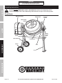
Functions
Mixer Blade
Upper Drum
Motor Assembly
Control
Handle
Stand
Wheel Bracket
Wheel
Lower Drum
Arm
Leg
Handle
Control
Plate

Page 11For technical questions, please call 1-888-866-5797.Item 61932
NOTICE
FOR CEMENT AND MORTAR ONLY.
Do not use with Epoxy 2-part resin mix.
SAFETYOPERATIONMAINTENANCE SETUP
General Operating Instructions
1. Place the Cement Mixer on a solid, even surface.
WARNING! Do not attempt to move the Cement
Mixer when it is full and/or in operation. Block
the wheels with wheel chocks (not included).
2. Connect the Power Cord to an electric
outlet (or properly rated grounded
three prong extension cord).
3. Add material to the Drum. Typical maximum
quantities include: 2 gallons water with
3 shovels of cement and 15 shovels aggregate
rock (using a size 3 shovel, not included).
4. Adjust the Drum angle by pulling on the Control
Handle. First, disengage the locking pins by
pulling the Control Handle away from the drum
and then pushing on the Handle until the desired
angle is reached. Re-engage the locking pins.
5. Flip the switch to “ON” (I) position.
6. Once materials are mixed, tilt Drum and
dump materials where needed. The materials
are dumped while the Drum is rotating.
CAUTION! Never leave the Cement Mixer running while
unattended. Do not turn Mixer off while full of cement.
7. When finished, flip the Switch to the “OFF” (O)
position and disconnect the Power Cord.
8. Tilt the Drum angle as far down as
possible to drain all fluids from Drum.
9. Clean, then store out of children’s reach.

Page 12 For technical questions, please call 1-888-866-5797. Item 61932
NOTICE
FOR CEMENT AND MORTAR ONLY.
Do not use with Epoxy 2-part resin mix.
SAFETY OPERATION MAINTENANCESETUP
Maintenance and Servicing
Procedures not specifically explained in this manual must
be performed only by a qualified technician.
TO PREVENT SERIOUS INJURY FROM ACCIDENTAL OPERATION:
Turn the Power Switch of the tool to its “OFF” position and unplug the tool from its
electrical outlet before performing any inspection, maintenance, or cleaning procedures.
TO PREVENT SERIOUS INJURY FROM TOOL FAILURE:
Do not use damaged equipment. If abnormal noise or vibration
occurs, have the problem corrected before further use.
Cleaning, Maintenance, and Lubrication
1. BEFORE EACH USE, inspect the general
condition of the tool. Check for:
• Loose hardware
• Misalignment or binding of moving parts
• Cracked or broken parts
• Damaged electrical wiring
• Damaged or cracked belts
• Any other condition that may
affect its safe operation.
2. AFTER USE, immediately wash out all debris
from the inside and outside of the Cement Mixer.
Scrub the inside of the Drum with a stiff, long
handled bristle brush for best results. Wipe
external surfaces of the tool with clean cloth.
3. DO NOT apply water in or around the Motor Cover.
4. PERIODICALLY recheck all fasteners
and other connections for tightness.
5. WARNING! If the supply cord of this
power tool is damaged, it must be replaced
only by a qualified service technician.
Belt Inspection and Tensioning
1. Retighten V-Belt after the first 25 hours of use.
To test the tension, follow the steps below.
2. Remove Motor Cover.
3. Examine Belt for cracks, tears in the
backing, or other damage. Replace Belt
if damaged according to steps below:
a. Loosen the Motor Bracket bolts and slide
the Bracket up as far as possible.
b. Slide the old Belt off of the Drum Pulley first,
then remove it from the Motor Pulley.
c. Put the new belt around the Motor Pulley
first, then around the Drum Pulley.
d. Move the Motor Bracket down until the Belt is
properly tensioned according to the directions
below. Tighten the Motor Bracket bolts.
4. Check and adjust belt tension
according to the steps below:
Deflection
Distance
a. Press on the center of the longest span
on the belt with moderate finger pressure.
Then measure the deflection distance,
the distance that the belt moved. The belt
should deflect anywhere from 1/2" to 3/4".
b. If the belt deflects too much, tighten belt
by loosening the Motor Bracket bolts and
moving the Motor away from the Drum Pulley
slightly. Tighten Motor Bracket bolts and
retest tension. If the belt is too long to be
properly tensioned, it must be replaced.
c. If the belt deflects too little, loosen the Motor
Bracket bolts and lift Bracket upward. Tighten
Motor Bracket bolts and retest tension.
5. Replace Motor Cover.

Page 13For technical questions, please call 1-888-866-5797.Item 61932
NOTICE
FOR CEMENT AND MORTAR ONLY.
Do not use with Epoxy 2-part resin mix.
SAFETYOPERATIONMAINTENANCE SETUP
Troubleshooting
Problem Possible Causes Likely Solutions
Tool will not start. 1. Cord not connected.
2. No power at outlet.
3. Internal damage or wear.
1. Check that cord is plugged in.
2. Check power at outlet. If outlet is unpowered, turn
off tool and check circuit breaker. If breaker is
tripped, make sure circuit has the correct capacity
for the tool and circuit has no other loads.
3. Have technician service tool.
Tool operates slowly. Extension cord too long or
wire size too small.
Eliminate use of extension cord. If an extension
cord is needed, use shorter/heavier gauge cord.
See Extension Cords in GROUNDING section.
Excessive noise
or rattling.
1. Belt too loose (slipping) or
too tight (bearing damage).
2. Internal damage or wear.
1. Properly tension belt.
2. Have technician service tool.
Overheating/
Overloading.
1. Running at 100% load
for extended time.
2. Blocked motor housing vents.
3. Motor being strained by long or
small diameter extension cord.
1. Allow for lighter no-load intervals.
2. Wear ANSI-approved safety goggles and NIOSH-
approved dust mask/respirator while blowing
dust out of motor using compressed air.
3. Eliminate use of extension cord. If an
extension cord is needed, use one with the
proper diameter for its length and load. See
Extension Cords in GROUNDING section.
Follow all safety precautions whenever diagnosing or servicing the tool.
Disconnect power supply before service.

Page 14 For technical questions, please call 1-888-866-5797. Item 61932
NOTICE
FOR CEMENT AND MORTAR ONLY.
Do not use with Epoxy 2-part resin mix.
SAFETY OPERATION MAINTENANCESETUP
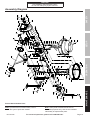
Parts List and Diagram
Parts List
Part Description Qty
1 Cotter Pin 5×40 2
2 Flat Washer 27 4
3 Wheel 2
4 Wheel Bracket 1
5 Hex Flange Nut M8 18
6 Motor Bracket 1
7 Power Cord 1
8 Bushing M12 3
9 Motor Cover 1
10 Flat Washer 4 15
11 Cross-Head Screw M4×12 4
12 Screw ST3.5×9.5 4
13 Switch 1
14 Switch Panel 1
15 Overload Protection Device 5A 1
16 Hex Bolt M6×20 5
17 Spring Washer 4 4
18 Nut M4 4
19 Ground Wire 1
20 Serrated Washer 1
21 Terminal Box 1
22 Cross-Head Screw M6×15 2
23 Spring Washer 6 2
24 Flat Washer 6 2
25 Flat Key 5×35 1
26 Drum Pulley 1
27 Spacer 2
28 Hex Bolt M8×20 4
29 Spring Washer 8 6
30 Flat Washer 8 4
31 Motor Hood 1
32 Nut M6 13
33 Bearing 6002ZZ 2
34 Ring Shield Ø38 4
35 Support Bracket Seat 2
36 Pinion Shaft 1
37 Gear 1
38 Flat Key 5×12 1
39 Gear Cover 1
40 Cross-Head Screw M4×30 3
Part Description Qty
41 Handle Control Plate 1
42 Hex Bolt M10×70 1
43 Coil Spring 1
44 Nut M10 1
45 Flat Washer 10 2
46 Control Handle 1
47 Rubber Handle 3
48 Lower Drum 1
49 Bearing Cover, Upper 1
50 Bearing 6206Z 2
51 Shaft 1
52 Nut M8 6
53 Bearing Cover, Lower 1
54 Hex Bolt M8×16 10
55 Flat Washer 8 26
56 Seal Gasket 18
57 Bolt M6x16 8
58 Flat Washer 6 8
59 Upper Drum 1
60 Rubber Gasket 1
61 Hex Bolt M8×20 2
62 Mixer Blade 2
63 Rubber Gasket 2
64 Flat Key 5×25 1
65 Motor 1
66 Motor Pulley 1
67 Screw M6×12 1
68 V-Belt O-870 1
69 Hex Bolt M8×55 2
70 Hex Bolt M8×65 4
71 Hex Bolt M8×60 2
72 Clamp 1
73 Hex Bolt M8×70 2
74 Hex Bolt M14×30 1
75 Spring Washer 14 1
76 Flat Washer 1
77 Arm 1
78 Stand 1
79 Leg 1

Page 15For technical questions, please call 1-888-866-5797.Item 61932
NOTICE
FOR CEMENT AND MORTAR ONLY.
Do not use with Epoxy 2-part resin mix.
SAFETYOPERATIONMAINTENANCE SETUP
11
10
13
16
9
10
17
18
21
22
23
24
25
20
19
17
18
12
11
10
8
7
5
6
28
55
1
2
3
2
4
2
3
2
1
69
55
70
55
5
78
5
5
79
47
5
69
55
70
71
55
5
75
74
76
77
71
55
73
29
55
72
41
35
34
29
30
34
43
44
45
46
42
47
48
32
49
50
51
50
53
52
36
33
27
37
38
24
23
22
39
34
35
34
33
32
29
30
8
64
66
67
68
40
28
26
54
5
56
55
61
62
27
31
5
65
60
59
57
14
28
54
56
55
45
5
56
63
10
10
56
56
15
55
58
Assembly Diagram
Record Serial Number Here:
Note: If product has no serial number, record
month and year of purchase instead.
Note: Some parts are listed and shown for
illustration purposes only, and are not available
individually as replacement parts.

3491 Mission Oaks Blvd. • PO Box 6009 • Camarillo, CA 93011 • 1-888-866-5797
PLEASE READ THE FOLLOWING CAREFULLY
THE MANUFACTURER AND/OR DISTRIBUTOR HAS PROVIDED THE PARTS LIST AND ASSEMBLY DIAGRAM
IN THIS DOCUMENT AS A REFERENCE TOOL ONLY. NEITHER THE MANUFACTURER OR DISTRIBUTOR
MAKES ANY REPRESENTATION OR WARRANTY OF ANY KIND TO THE BUYER THAT HE OR SHE IS
QUALIFIED TO MAKE ANY REPAIRS TO THE PRODUCT, OR THAT HE OR SHE IS QUALIFIED TO REPLACE
ANY PARTS OF THE PRODUCT. IN FACT, THE MANUFACTURER AND/OR DISTRIBUTOR EXPRESSLY
STATES THAT ALL REPAIRS AND PARTS REPLACEMENTS SHOULD BE UNDERTAKEN BY CERTIFIED AND
LICENSED TECHNICIANS, AND NOT BY THE BUYER. THE BUYER ASSUMES ALL RISK AND LIABILITY
ARISING OUT OF HIS OR HER REPAIRS TO THE ORIGINAL PRODUCT OR REPLACEMENT PARTS
THERETO, OR ARISING OUT OF HIS OR HER INSTALLATION OF REPLACEMENT PARTS THERETO.
Limited 90 Day Warranty
Harbor Freight Tools Co. makes every effort to assure that its products meet high quality and durability standards,
and warrants to the original purchaser that this product is free from defects in materials and workmanship for the
period of 90 days from the date of purchase. This warranty does not apply to damage due directly or indirectly,
to misuse, abuse, negligence or accidents, repairs or alterations outside our facilities, criminal activity, improper
installation, normal wear and tear, or to lack of maintenance. We shall in no event be liable for death, injuries
to persons or property, or for incidental, contingent, special or consequential damages arising from the use of
our product. Some states do not allow the exclusion or limitation of incidental or consequential damages, so the
above limitation of exclusion may not apply to you. THIS WARRANTY IS EXPRESSLY IN LIEU OF ALL OTHER
WARRANTIES, EXPRESS OR IMPLIED, INCLUDING THE WARRANTIES OF MERCHANTABILITY AND FITNESS.
To take advantage of this warranty, the product or part must be returned to us with transportation charges
prepaid. Proof of purchase date and an explanation of the complaint must accompany the merchandise.
If our inspection verifies the defect, we will either repair or replace the product at our election or we may
elect to refund the purchase price if we cannot readily and quickly provide you with a replacement. We will
return repaired products at our expense, but if we determine there is no defect, or that the defect resulted
from causes not within the scope of our warranty, then you must bear the cost of returning the product.
This warranty gives you specific legal rights and you may also have other rights which vary from state to state.
-
 1
1
-
 2
2
-
 3
3
-
 4
4
-
 5
5
-
 6
6
-
 7
7
-
 8
8
-
 9
9
-
 10
10
-
 11
11
-
 12
12
-
 13
13
-
 14
14
-
 15
15
-
 16
16


Harbor Freight Tools 3_1/2 Cubic Ft. Cement Mixer Owner's manual
- Category
- Power tools
- Type
- Owner's manual
- This manual is also suitable for
Ask a question and I''ll find the answer in the document
Finding information in a document is now easier with AI
Related papers
-
Chicago Electric 61369 Owner's manual
-
Harbor Freight Tools 90178 User manual
-
-
-
-
-
-
Other documents
-
King Canada KC-15CM-2 User manual
-
Central Machinery 3-1/2 Cubic Ft. Cement Mixer Owner's manual
-
-
-
Ryobi RMX001 Owner's manual
-
-
-
Buffalo Tools CME35 User manual
-
-
Lumberjack ECM550 Owner's manual