Page is loading ...

9105 / 9107
Dry-well Calibrator
User’s Guide
Rev. 2A2801

Rev.2A2801
© Copyright,1991–2002
Hart Scientific, Inc.
799 E. Utah Valley Drive
American Fork, Utah 84003-9775
Telephone: (801) 763-1600 • Fax: (801) 763-1010
Internet: http://www.hartscientific.com
E-mail: support@hartscientific.com

Table of Contents
1 Before You Start ............................1
1.1 Symbols Used .......................................1
1.2 Safety Information.....................................2
1.2.1 Warnings..................................................2
1.2.2 Cautions ..................................................4
1.3 Hart Scientific Authorized Service Centers .........................5
2 Introduction ..............................7
3 Specifications and Environmental Conditions ...............9
3.1 Specifications .......................................9
3.2 Environmental Conditions .................................9
3.3 Warranty.........................................10
4 Safety Guidelines ...........................11
5 Quick Start ..............................13
5.1 Unpacking ........................................13
5.2 Set-up ..........................................13
5.3 Power ..........................................13
5.4 Setting the Temperature .................................14
6 Parts and Controls...........................15
6.1 Rear Panel ........................................15
6.2 Front Panel........................................16
6.3 Constant Temperature Block Assembly ..........................17
6.3.1 Constant Temperature Block........................................17
6.3.2 Probe Sleeves and Tongs .........................................17
6.4 Well Insulator (9107only) ................................18
7 General Operation...........................21
7.1 Calibrator Set-Up .....................................21
7.2 Switching to 230 V Operation (9107 only) ........................21
7.3 Setting the Temperature .................................22
7.4 Calibrating Probes ....................................22
i

8 Controller Operation..........................23
8.1 Well Temperature.....................................23
8.2 Reset Cut-out.......................................23
8.3 Temperature Set-point ..................................25
8.3.1 Programmable Set-points .........................................25
8.3.2 Set-point Value ..............................................26
8.3.3 Temperature Scale Units .........................................26
8.4 Scan ...........................................26
8.4.1 Scan Control ...............................................27
8.4.2 Scan Rate.................................................27
8.5 Temperature Display Hold ................................27
8.5.1 Hold Temperature Display.........................................28
8.5.2 Mode Setting ...............................................28
8.5.3 Scan Hold.................................................29
8.5.4 Switch Wiring ...............................................29
8.5.5 Switch Test Example............................................29
8.6 Ramp and Soak Program Menu..............................31
8.6.1 Number of Program Set-points ......................................31
8.6.2 Set-points.................................................32
8.6.3 Program Soak Time............................................32
8.6.4 Program Function Mode..........................................33
8.6.5 Program Control .............................................33
8.7 Secondary Menu .....................................34
8.8 Heating Power ......................................34
8.9 Proportional Band ....................................34
8.10 Cut-out..........................................36
8.11 Controller Configuration .................................37
8.11.1 Probe Parameters ............................................37
8.11.1.1R
0
.................................................37
8.11.1.2ALPHA...............................................38
8.11.1.3DELTA ...............................................38
8.11.1.4BETA ...............................................38
8.11.2 Operating Parameters ..........................................38
8.11.2.1Temperature Scale Units ......................................38
8.11.2.2Cut-out Reset Mode ........................................38
8.11.2.3Soak Stability ...........................................39
8.11.3 Serial Interface Parameters ........................................39
8.11.3.1BAUD Rate ............................................39
8.11.3.2Sample Period...........................................40
8.11.3.3Duplex Mode ...........................................40
8.11.3.4Linefeed..............................................40
8.11.4 IEEE-488 Parameters ...........................................41
8.11.4.1IEEE-488 Address .........................................41
8.11.4.2Termination ............................................41
8.11.5 Calibration Parameters ..........................................42
8.11.5.1CTO ................................................42
8.11.5.2BO and BG ............................................42
ii

8.11.5.3SCO ................................................42
9 Digital Communication Interface ....................43
9.1 Serial Communications ..................................43
9.1.1 Wiring ..................................................43
9.1.2 Setup ...................................................43
9.1.2.1 BAUD Rate ............................................44
9.1.2.2 Sample Period...........................................44
9.1.2.3 Duplex Mode ...........................................44
9.1.2.4 Linefeed..............................................44
9.1.3 Serial Operation .............................................45
9.2 IEEE-488 Communication .................................45
9.2.1 Setup ...................................................45
9.2.1.1 IEEE-488 Interface Address ....................................45
9.2.2 IEEE-488 Operation ............................................45
9.3 Interface Commands ...................................46
10 Test Probe Calibration .........................51
10.1 Comparison Methods ...................................51
10.1.1 Direct Calibration .............................................51
10.1.2 Comparison Calibration ..........................................51
10.1.3 Calibration of Multiple Probes .......................................52
10.2 Dry-Well Characteristics..................................52
10.2.1 Vertical Gradient .............................................53
10.2.2 Stabilization and Accuracy ........................................53
11 Calibration Procedure .........................55
11.1 Calibration Procedure...................................55
11.1.1 Calibration Equipment ..........................................55
11.1.2 Calibration ................................................55
12 Maintenance .............................57
13 Troubleshooting ............................59
13.1 Troubleshooting .....................................59
13.2 Comments ........................................60
13.2.1 EMC Directive ...............................................60
13.2.2 Low Voltage Directive (Safety) ......................................60
13.3 Wiring Diagrams .....................................61
iii

iv
Figures
Figure 1 Top View............................................3
Figure 2 Rear Panel ..........................................15
Figure 3 Front Panel..........................................16
Figure 4 Well and Insert ........................................17
Figure 5 Well Insulator Top View ....................................19
Figure 6 Controller Function Flowchart .................................24
Figure 7 Switch Test Data .......................................31
Figure 8 Well temperature fluctuation at various proportional band settings ..............35
Figure 9 Serial Cable Wiring Diagram .................................43
Figure 10 9105 Wiring Diagram ....................................61
Figure 11 9107 Wiring Diagram ....................................62


1 Before You Start
1.1 Symbols Used
Table 1 lists the symbols used on the instrument or in this manual and the
meaning of each symbol.
Symbol Description
AC (Alternating Current)
AC-DC
Battery
Complies with European Union directives
DC
Double Insulated
Electric Shock
Fuse
PE Ground
Hot Surface (Burn Hazard)
Read the User’s Manual (Important Information)
Off
On
9105/9107 1
1 Before You Start
Table 1 International Electrical Symbols

Symbol Description
Canadian Standards Association
OVERVOLTAGE (Installation) CATEGORY II, Pollution Degree 2 per IEC1010-1 refers to the
level of Impulse Withstand Voltage protection provided. Equipment of OVERVOLTAGE CATE
-
GORY II is energy-consuming equipment to be supplied from the fixed installation. Exam
-
ples include household, office, and laboratory appliances.
C-TIC Australian EMC
1.2 Safety Information
Use the instrument only as specified in this manual. Otherwise, the protection
provided by the instrument may be impaired. Refer to the safety information
below and throughout the manual.
The following definitions apply to the terms “Warning” and “Caution”.
• “Warning” identifies conditions and actions that may pose hazards to the
user.
• “Caution” identifies conditions and actions that may damage the instru-
ment being used.
1.2.1
Warnings
To avoid possible electric shock or personal injury, follow these guidelines.
•
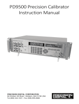
BURN HAZARD – Do Not touch the well access surface of the unit.
(Refer to Figure 1 on page 3.)
•
The temperature of the well access (1) will be the same as the actual tem
-
perature shown on the display (2), e.g. if the unit is set at 600°C and the
display reads 600°C, the well is at 600°C.
•
The top sheet metal (3) of the dry-well may exhibit extreme temperatures
for areas close to the well access.
•
The air over the well can reach temperatures greater than 200°C.
PROBES SHOULD ONLY BE INSERTED AND REMOVED FROM
THE UNIT WHEN THE UNIT IS SET AT TEMPERATURES LESS
THAN 200°C.
•
DO NOT TURN OFF THE UNIT AT TEMPERATURES HIGHER
THAN 100°C. This could create a hazardous situation. Select a set-point
less than 100°C and allow the unit to cool before turning it off.
2 Hart Scientific
1 Before You Start
CAT II

9105/9107 3
1 Before You Start
Set Down Up Exit
9105
1
2
3
WARNING:
THIS AREA IS HOT
Figure 1 Top View

•
DO NOT REMOVE INSERTS AT HIGH TEMPERATURES. Inserts
will be the same temperature as the display temperature. Use extreme care
when removing hot inserts.
•
DO NOT operate this unit without a properly grounded, properly polar
-
ized power cord.
•
DO NOT connect this unit to a non-grounded, non-polarized outlet.
•
HIGH VOLTAGE is used in the operation of this equipment. SEVERE
INJURY OR DEATH may result if personnel fail to observe safety pre
-
cautions. Before working inside the equipment, turn power off and dis
-
connect power cord.
•
Always replace the fuse with one of the same rating, voltage, and type.
•
Overhead clearance is required. DO NOT place unit under a cabinet or
other structure.
•
DO NOT use this unit for any application other than calibration work.
• DO NOT use this unit in environments other than those listed in the
user’s manual.
• DO NOT turn the unit upside down with the inserts in place; the inserts
will fall out of the unit.
• DO NOT operate near flammable materials.
• Use of this instrument at HIGH TEMPERATURES for extended periods
of time requires caution.
•
Completely unattended high temperature operation is not recom
-
mended for safety reasons.
•
Before initial use, after transport and anytime the dry-well has not been
energized for more than 10 days, the calibrator must be energized for a
dry-out period of 1 to 2 hours before it can be assumed to meet all of the
safety requirements of the IEC1010-1.
•
Follow all safety guidelines listed in the user’s manual.
•
CALIBRATION EQUIPMENT should only be used by TRAINED PER
-
SONNEL.
1.2.2
Cautions
To avoid possible damage to the instrument, follow these guidelines.
•
Components and heater lifetime can be shortened by continuous high
temperature operation.
4 Hart Scientific
1 Before You Start

•
Components and heater lifetime can be shortened by continuous high
temperature operation.
•
Most probes have handle temperature limits. Be sure that the probe handle
temperature limit is not exceeded in the air above the unit.
•
(9107 only) Always use the well insulator, see Section 5.4.
•
Allow for test probe expansion inside the well as the dry-well heats.
•
DO NOT use fluids to clean out the well.
•
Never introduce any foreign material into the probe hole of the insert.
Fluids, etc. can leak into the calibrator causing damage.
•
DO NOT change the values of the calibration constants from the factory
set values. The correct setting of these parameters is important to the
safety and proper operation of the calibrator.
•
DO NOT slam the probe stems in to the well. This type of action can
cause a shock to the sensor and affect the calibration.
• DO use a ground fault interrupt device.
1.3 Hart Scientific Authorized Service Centers
Please contact one of the following authorized Service Centers to coordinate
service on your Hart product:
Hart Scientific, Inc.
799 E. Utah Valley Drive
American Fork, UT 84003-9775
USA
Phone: +1.801.763.1600
Telefax: +1.801.763.1010
E-mail: [email protected]
Fluke Nederland B.V.
Customer Support Services
Science Park Eindhoven 5108
5692 EC Son
NETHERLANDS
Phone: +31-402-675300
9105/9107 5
1 Before You Start

Telefax: +31-402-675321
E-mail: [email protected]
Fluke Int'l Corporation
Service Center - Instrimpex
Room 2301 Sciteck Tower
22 Jianguomenwai Dajie
Chao Yang District
Beijing 100004, PRC
CHINA
Phone: +86-10-6-512-3436
Telefax: +86-10-6-512-3437
E-mail: [email protected]
Fluke South East Asia Pte Ltd.
Fluke ASEAN Regional Office
Service Center
83 Clemenceau Avenue
#15-15/06 Ue Square
239920
SINGAPORE
Phone: +65-737-2922
Telefax: +65-737-5155
E-mail: [email protected]
When contacting these Service Centers for support, please have the following
information available:
•
Model Number
•
Serial Number
•
Voltage
•
Complete description of the problem
6 Hart Scientific
1 Before You Start

2 Introduction
The Hart Scientific Model 9105/9107 dry-well calibrator may be used as a por
-
table instrument for calibration of temperature probes. The 9105 operates over
the range of –25°C and 140°C. The 9107 operates over the range of –45°C to
140°C.
These dry-well calibrators feature an interchangeable aluminum probe sleeve
along with 4 fixed wells. The temperature is accurately controlled by Hart's
precision temperature controller.
The calibrator controller uses a precision platinum RTD as a sensor and con
-
trols the well temperature with thermoelectric modules. The LED front panel
display continuously shows the current well temperature. The temperature may
be easily set with the control buttons to any desired temperature within the
specified range.
The 9105/9107 dry-well calibrator was designed for portability, moderate cost,
and ease of operation. With proper use the instrument should provide continued
accurate calibration of temperature sensors and devices. The user should be fa-
miliar with the safety guidelines and operating procedures of the calibrator as
described in the User’s Guide.
9105/9107 7
2 Introduction

3 Specifications and Environmental Conditions
3.1 Specifications
The following table lists the specifications for this instrument. Accuracy speci
-
fications are applicable for a one-year calibration interval. In line with normal
prudent metrology practices, Hart Scientific recommends a short-cycle interval
of six months for new units during the first year.
9105 9107
Power
115 VAC (±10%), 50/60 Hz, 230 VAC (±10%), 350 watts
Ambient Temperature
5–50°C (40–120°F)
Operating Range
–25°C to 140°C
(–32°C to 284°F)
at 25°C (77°F)
–45°C to 140°C
(–49°F to 285°F)
at 25°C (77°F)
Resolution
0.01°C or 0.01°F
Accuracy:
Drilled Wells
±0.2°C (0.36°F)
Center Well
±0.1°C (0.18°F) with 6.35 mm (1/4”)probe
Uniformity:
Drilled Wells
±0.05°C (0.09°F)
Center Well
±0.2°C (0.36°F) with 6.35 (1/4”) mm probe
Control Stability
0.02°C (0.04°F)
Controller
Hybrid analog/digital controller with data retention
Test Wells
One 3/4" dia. x 6" deep, two 1/4" dia. x 6", one 3/16" dia. x 6" deep, and
one 1/8" x 6" deep
Size
12.5"Hx8"Wx10.5" D
Weight
30 lb. including well sleeve
Safety
OVERVOLTAGE (Installation) CATEGORY II, Pollution Degree 2 per IEC1010-1
Fuse Rating
115 V: 4 A (slow blow) 250 V
230 V: 3.15 A (slow blow) 250 V
3.2 Environmental Conditions
Although these instruments have been designed for optimum durability and
trouble-free operation, they must be handled with care. The instrument should
not be operated in an excessively dusty or dirty environment. Maintenance and
cleaning recommendations can be found in the Maintenance Section of this
manual.
The instrument operates safely under the following conditions:
9105/9107 9
3 Specifications and Environmental Conditions

•
temperature range 5 - 50°C (41 - 122°F)
•
ambient relative humidity 15 - 50%
•
pressure - 75kPa - 106kPa
•
mains voltage within ± 10% of nominal
•
vibrations in the calibration environment should be minimized
•
altitude less than 2,000 meters
3.3 Warranty
Hart Scientific, Inc. (Hart) warrants this product to be free from defects in ma
-
terial and workmanship under normal use and service for a period as stated in
our current product catalog from the date of shipment. This warranty extends
only to the original purchaser and shall not apply to any product which, in
Hart’s sole opinion, has been subject to misuse, alteration, abuse or abnormal
conditions of operation or handling.
Software is warranted to operate in accordance with its programmed instruc-
tions on appropriate Hart products. It is not warranted to be error free.
Hart’s obligation under this warranty is limited to repair or replacement of a
product which is returned to Hart within the warranty period and is determined,
upon examination by Hart, to be defective. If Hart determines that the defect or
malfunction has been caused by misuse, alteration, abuse or abnormal condi-
tions or operation or handling, Hart will repair the product and bill the pur-
chaser for the reasonable cost of repair.
To exercise this warranty, the purchaser must forward the product after calling
or writing Hart for authorization. Hart assumes NO risk for in-transit damage.
For service or assistance, please contact a Hart Scientific Authorized Customer
Service Center (see Section 1.3).
THE FOREGOING WARRANTY IS PURCHASER’S SOLE AND EXCLU
-
SIVE REMEDY AND IS IN LIEU OF ALL OTHER WARRANTIES, EX
-
PRESS OR IMPLIED, INCLUDING BUT NOT LIMITED TO ANY
IMPLIED WARRANTY OR MERCHANTABILITY, OR FITNESS FOR ANY
PARTICULAR PURPOSE OR USE. HART SHALL NOT BE LIABLE FOR
ANY SPECIAL, INDIRECT, INCIDENTAL, OR CONSEQUENTIAL DAM
-
AGES OR LOSS WHETHER IN CONTRACT, TORT, OR OTHERWISE.
10 Hart Scientific
3 Specifications and Environmental Conditions

4 Safety Guidelines
•
Operate the instrument in room temperatures between 5–50°C
(41–122°F). Allow sufficient air circulation by leaving at least 6 inches of
space between the instrument and nearby objects. DO NOT place under a
cabinet or other structure. Allow for overhead clearance.
•
The dry-well is a precision instrument. Although it has been designed for
optimum durability and trouble free operation, it must be handled with
care. Always carry the unit in an upright position to prevent the probe
sleeves from dropping out. The convenient fold-up handle allows one
hand carrying. The instrument should not be operated in excessively wet,
oily, dusty, or dirty environments. It is important to keep the well of the
instrument clean and clear of any foreign matter. DO NOT operate near
flammable materials.
•
DO NOT use fluids to clean out the well.
• The instrument can generate extreme temperatures. Precautions must be
taken to prevent personal injury or damage to objects. Probes may be ex-
tremely hot or cold when removed from the instrument. Cautiously handle
probes to prevent personal injury. Always use the special sleeve tongs that
are supplied with the calibrator to remove the sleeve. Carefully place
probes on a heat/cold resistant surface or rack until they are at room tem-
perature. Never place any objects other than the special probe sleeves sup-
plied with the calibrator into the well.
• Use only a grounded AC mains supply of the appropriate voltage to
power the instrument. The Model 9105 dry-well requires 3 amps SB at
115 VAC (±10%), 50/60 Hz, 1.6 amps T at 230 VAC (±10%). The Model
9107 dry-well requires 4 amps SB at 115 VAC (±10%), 50/60 Hz, 3.15
amps T at 230 VAC (±10%).
•
Before initial use, after transport, and anytime the dry-well has not been
energized for more than 10 days, the instrument needs to be energized for
a “dry-out” period of 1-2 hours before it can be assumed to meet all of the
safety requirements of the IEC 1010-1.
•
The instrument is equipped with operator accessible fuses. If a fuse
blows, it may be due to a power surge or failure of a component. Replace
the fuse once. If the fuse blows a second time, it is likely caused by fail
-
ure of a component part. If this occurs, contact Hart Scientific Customer
Service. Always replace the fuse with one of the same rating, voltage, and
type. Never replace the fuse with one of a higher current rating.
•
If a mains supply power fluctuation occurs, immediately turn off the in
-
strument. Power bumps from brown-outs and black-outs could damage
9105/9107 11
4 Safety Guidelines

the instrument. Wait until the power has stabilized before re-energizing
the instrument.
12 Hart Scientific
4 Safety Guidelines

5 Quick Start
5.1 Unpacking
Unpack the dry-well carefully and inspect it for any damage that may have oc
-
curred during shipment. If there is shipping damage, notify the carrier
immediately.
Verify that the following components are present:
•
9105 or 9107 Dry-well
•
2173 Insert, 1/4” Aluminum
•
Power Cord
•
Manual
•
Two Well Insulators (9107 only)
• Tongs (insert removal tool)
5.2 Set-up
Place the calibrator on a flat surface with at least 6 inches of free space around
the instrument. Overhead clearance is required. DO NOT place under a cabinet
or structure. Plug the power cord into a grounded mains outlet. Observe that the
nominal voltage corresponds to that indicated on the back of the calibrator.
Carefully insert the probe sleeve into the well. Probe sleeves should be of the
smallest hole diameter possible still allowing the probe to slide in and out eas
-
ily. Sleeves of various sizes are available for Hart Scientific. The well must be
clear of any foreign objects, dirt and grit before the sleeve is inserted. The
sleeve is inserted with the two small tong holes positioned upward.
Turn on the power to the calibrator by toggling the switch on the power entry
module. The fan should begin quietly blowing air through the instrument and
the controller display should illuminate after 3 seconds. After a brief self-test
the controller should begin normal operation. If the unit fails to operate please
check the power connection.
The display will begin to show the well temperature and the well heater will
start operating to bring the temperature of the well to the set-point temperature.
5.3 Power
Plug the dry-well power cord into a mains outlet of the proper voltage, fre
-
quency, and current capability. Typically this will be 115 VAC (±10%), 50/60
Hz (230 VAC ±10%, 50/60 Hz). Turn the dry-well on using the rear panel
9105/9107 13
5 Quick Start

“POWER” switch. The dry-well will turn on and begin to heat to the previously
programmed temperature set-point. The front panel LED display will indicate
the actual dry-well temperature.
The 9107 is field switchable between 115 V and 230 V. Refer to Section 7.2,
Switching to 230 V Operation, for information on switching the voltage.
5.4 Setting the Temperature
Section 8.3 explains in detail how to set the temperature set-point on the cali
-
brator using the front panel keys. The procedure is summarized here.
1. Press “SET” twice to access the set-point value.
2. Press “UP” or “DOWN” to change the set-point value.
3. Press “SET” to program in the new set-point.
4. Press “EXIT” to return to the temperature display.
When the set-point temperature is changed the controller will switch the well
heater on or off to raise or lower the temperature. The displayed well tempera-
ture will gradually change until it reaches the set-point temperature. The well
may require 5 to 10 minutes to reach the set-point depending on the span. An-
other 5 to 10 minutes is required to stabilize with ±0.1°C of the set-point. Ulti-
mate stability may take 15 to 20 minutes more of stabilization time.
14 Hart Scientific
5 Quick Start
/