
Ella Gel Coat Walk In Tub
OWNER'S MANUAL
REPRESENTING THESE MODEL NUMBERS:
264503L / 264503R
HYDROTHERAPY
264504L / 264504R
DUAL MASSAGE
264502L / 264502R
AIR MASSAGE
264501L / 264501R
SOAKING
Small 45″ Long
284803L / 284803R
HYDROTHERAPY
284804L / 284804R
DUAL MASSAGE
284802L / 284802R
AIR MASSAGE
284801L / 284801R
SOAKING
Short 45″ Long
313703L / 313703R
HYDROTHERAPY
313704L / 313704R
DUAL MASSAGE
313702L / 313702R
AIR MASSAGE
313701L / 313701R
SOAKING
Front Entry
335503L / 335503R
HYDROTHERAPY
335504L / 335504R
DUAL MASSAGE
335502L / 335502R
AIR MASSAGE
335501L / 335501R
SOAKING
Bariatric 33
305503L / 305503R
HYDROTHERAPY
305504L / 305504R
DUAL MASSAGE
305502L / 305502R
AIR MASSAGE
305501L / 305501R
SOAKING
Deep 46″ Long
355503L / 355503R
HYDROTHERAPY
355504L / 355504R
DUAL MASSAGE
355502L / 355502R
AIR MASSAGE
355501L / 355501R
SOAKING
Bariatric 35
325203L / 325203R
HYDROTHERAPY
325204L / 325204R
DUAL MASSAGE
325202L / 325202R
AIR MASSAGE
325201L / 325201R
SOAKING
Wheelchair Acess
306003L / 306003R
HYDROTHERAPY
306002L / 306002R
AIR MASSAGE
306001L / 306001R
SOAKING
Lay Down
305213L / 305213R
HYDROTHERAPY
305214L / 305214R
DUAL MASSAGE
305212L / 305212R
AIR MASSAGE
305211L / 305211R
SOAKING
Low 3.5″ Threshold
326003L / 326003R
HYDROTHERAPY
326004L / 326004R
DUAL MASSAGE
326002L / 326002R
AIR MASSAGE
326001L / 326001R
SOAKING
Long


Important Safety Instructions ............................................................................................................ 1
Unpack and Inspect .......................................................................................................................... 2
Preparing for Installation ................................................................................................................... 3
Installation of Bath ............................................................................................................................. 4
Plumbing Installation ......................................................................................................................... 5
Overow Plumbing Diagram ............................................................................................................ 6
Installing the Faucet System ............................................................................................................. 7
Faucet Options ................................................................................................................................... 8
Huntington Brass 5 Piece Faucet ..................................................................................................9 -11
Electrical Installation Requirements ................................................................................................12
Air Massage System ..........................................................................................................................13
Hydro Massage System ....................................................................................................................14
Final Inspections ................................................................................................................................15
Finishing Installation ..........................................................................................................................16
Operating Instructions ................................................................................................................. 17-19
Cleaning and Maintenance .......................................................................................................... 20
FAQ’s ...................................................................................................................................................21
Warranty Information ...................................................................................................................... 22
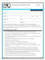
Warranty Activation Form .......................................................................................................... 23-24
www.ellasbubbles.com 07/14
Contents


WARNING:
***Read through the entire manual completely before beginning installation.***
Contract a licensed plumber and electrician for installation. Be sure you and your
contractor are aware and follow all local plumbing and electrical codes. Your Ella Walk
In Tub is not intended for outdoor use. Install the tub in accordance with the instructions
in the manual. Use ONLY the parts and accessories provided or as recommended by the
manufacturer.
CAUTION:
When using this product, basic precautions should always be followed. Read and follow all
instruction pertaining to risk of re, electric shock and injury. Make sure to have your licensed
electrician test all connections to the dedicated line, including the GFCI.
Risk of electric shock; Do not permit electric appliances within 3 feet (1.5m) of the tub. i.e.:
hair dryers, lamps, phones, radios, televisions, etc.
To reduce the risk of injury, do not permit children or individuals with disabilities to use this
product unless they are supervised by an able-bodied adult at all times. Never drop or
insert any objects into any openings.
Do not turn on the hydro jets without water reaching the waterline. The waterline is the point
where all jets are covered with water.
DANGER:
Temperature in excess of 100.4 Fahrenheit (38 Celsius) may be harmful to your health. Check
and adjust the temperature before use. Consult your physician before using your Ella Walk
In Tub if you have a heart condition or other health issues. People using medications, herbal
remedies, sleep aids, and/or having adverse medical history should consult a physician
before using this product.
Pregnant women should NOT use this product before consulting their physician. Avoid the
use of alcohol, drug or other medication while using your Walk In Tub.
Be aware, hyperthermia is a risk when raising body temperature. Do no keep body
submerged in heated bath for extended periods of time. The symptoms of hyperthermia
include an increase in body temperature which can cause dizziness, lethargy, drowsiness
and fainting. Avoid using the heated bath after strenuous activity.
Exercise caution while entering and exiting your Ella Walk In Tub.
Important Safety Instructions
www.ellasbubbles.com Page 1 07/14

1. While unpacking your new Walk In Tub inspect the product and packing thoroughly for
freight damages.
If there are any noticeable damages ***DO NOT ACCEPT the unit from the carrier*** and
call us as soon as possible at: 1-800-480-6850
2. Upon receiving your Ella Walk In Tub, please open immediately and check for any
damages. Damages due to delivery MUST be reported to Ella within 48 hours of
receipt. You can report damages by calling 1-800-480-6850 or emailing us at
warranty@ellasbubbles.com.
3. While unpacking your new Walk In Tub, care should be used to retain the packaging in
case you discover damage through shipping and need to re-pack the Bath and return it
to sender.
4. Never lift the Walk In Tub by its plumbing xtures. Lift the tub only by its stainless steel
frame. Two people are required to move a Walk In Tub.
5. Inspect the plumbing for any ttings that may have loosened in transit.
6. WARNING!!! If the Walk In Tub door comes shipped with the door closed make sure you
leave it open overnight so the gasket becomes fully relaxed.
7. Follow all instructions in this manual. Failure to read and comply and read with all
instructions can result in product damage or injury to both installer and homeowner. It
will also result in assumption of all liability to the installer.
Unpack and Inspect
www.ellasbubbles.com Page 2 07/14

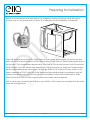
Remove access panels that are held on by magnets. Remove these by using the yellow
suction cups on the panel and put them in a safe place until installation is complete.
Place all accessories to the side. Make sure no loose parts are hanging. Lift and carry the
bath only by the deck or frame. Protect the bottom of the bath to avoid breaking the jets at
the bottom. Only accessories approved by Ella Walk In Tub should be used with this product.
All Ella Walk In Tubs are tested and operated in our factory prior to shipment. Transportation
and/or mishandling may cause leaks. Testing the Walk In Tub while you have access to all
sides is imperative! ONLY after all of the water and electrical testing is completed, and all
xtures have been checked, the tub should be installed to the surrounded wall or walls.
Place the Walk In Tub on a at surface where the water can be drained.
With a clean rag, clean the door seal on your Walk In Tub to remove any debris left from the
manufacturing process.
Preparing for Installation
www.ellasbubbles.com Page 3 07/14

1. Remove the existing tub and the wall and oor materials as required.
2. Clean area of any debris or trash.
3. Use 4 foot level and determine if the oor is level. If the oor is not level adjust all leveling
feet to perfectly level the tub.
4. Make sure you level the Walk In Tub from the highest elevation point on the oor.
Feet on the Walk In Tub need to be leveled
5. All leveling legs of the Walk In Tub must be resting on the oor evenly supporting the
weight of the bathtub, in order for the door to work properly without leaks.
6. Start by adjusting the outside legs and make sure they are level. Continue to adjust the
legs by adjusting the two (2) in the center of your Walk In Tub. Rough in your plumbing
options before leveling, as some options may cause clearance issues underneath the
tub.
Installation of Bath
www.ellasbubbles.com Page 4 07/14

1. Dry t the plumbing before nal assembly to make sure that the pipe lengths are correct
and there is proper clearance throughout.
2. Assemble kit as show. Check your local plumbing codes to insure that proper xatives
(glue) are used.
3. Tighten down the nuts.
4. Install Overow elbow with gasket. Secure to the tub with retaining plate and nut. Install
cover plate and secure with set screw.
5. Install a pipe section so that the door drain tube is located on the horizontal center line.
6. Install the waste elbow with actuator gasket. Secure to the bath with strainer plate and
nut.
CAUTION:
Be sure to adjust the stopper height to allow proper drain function. Test for proper drain
function before continuing.
7. Once the drain is effectively draining at the desired height, tighten the screw on top of
the strainer to secure drain cap height.
8. Check all connections and tighten down any loose ttings, set screws, etc.
Plumbing Installation
www.ellasbubbles.com Page 5 07/14

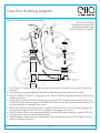
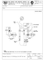
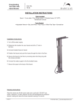
Over-ow Plumbing Diagram
Waste & Overow Assembly Instructions
Sch 40 PVC Fittings
Solid Brass Finished Trim
Adjustable Head Angle
Lever Handle for Overow
1. Dry Fit the PVC pipe prior to nal assembly to ensure the lengths are correct. Orient Tee
as show.
2. Glue ttings using appropriate cement and primer as required by local codes.
3. Mount 792W45 TO D505h-1 using the 4 ears. Place 792RW between Bath Shoe Elbow and
under side of tub.
4. Place a thin bead of silicone caulking around the D50-7 Strainer and place it in the tub
outlet. Draw the Strainer against the Bath Shoe Elbow with the Strainer Retainer Screw. Do
not over tighten or damage can occur.
5. Place the Overow Nut through the Overow Plate and draw the Flex Head against the
tub by tightening the Nut. Do not over tighten or damge can occur.
6. Slide Overow Plate onto stem extending from the Flex Head Assembly. Tighten D50-12H
into groove in stem to hold handle in place.
7. Adjust stopper height with the adjustment screw and holding the screw height in place
with the Stopper Lock Nut.
D50FH-2
FLex Head
Socket
D50FH-3
Socket Washer
D50FH-4
Socket Nut
D50FH-1 Flex
Head Assembly
Less Cable
792ws
Overflow
Gasket
D50-10
Overflow
Plate
D50-1
Overflow
Plate
D50-11
Overflow
Nut
D50-12H
Lever For
Handle
D50-5W
Stopper
Washer
D50-45
45”Cable
D50-3
Stopper
Lock Nut
D50-2T
Stopper
D50-4 Stopper
Adjustment Screw
D50-6
Strainer Retainer
D50-7
Strainer
792RW-LT
Bath Shoe Washer
Bath Show Elbow Less
Cable D50-8
4C-W
PVC Tee
www.ellasbubbles.com Page 6 07/14

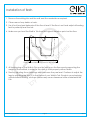
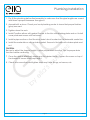
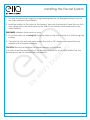
1. To install the faucet set, begin by using masking tape on the berglass surface over the
are to be marked-off and drilled.
2. Mark the position of the holes for the faucets/ taps onto the taped off area. Be sure that
your piping will not be obstructed by the Walk In Tub stainless steel framework or any
other obstacle.
REMEMBER: Measure twice and cut once.
3. To cut the holes use a coring bit. Using the tape to help with a clean cut, drill through the
surface.
4. Connect the hot and cold water supply lines with a 3/4" water heater type ex hose
adapter with a female connector.
CAUTION: Be sure the ex hose has rubber washers on both ends.
In a case where the plumbing is not on the same side as it is on your Ella Walk In Tub, the
plumbing may be run underneath your bathtub.
Installing the Faucet System
www.ellasbubbles.com Page 7 07/14

Ella Gel Coat Walk In Tubs comes with one of two types of faucets.
1. One Piece Chrome Finish Brass Faucet
Front Entry and Small 45" Long Walk In Tubs
2. Huntington Brass 5 Piece Roman Faucet
Narrow-Short-Deep-Bariatric-Low-Lay Down-Wheelchair-Long
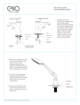
One Piece Chrome Finish Brass Faucet (comes installed only if requested)
Front Entry, Small
• Full body brass spout
• Hand shower with pull out hose
• Diverter for spout and hand shower
• Hot and cold water control valves
Installation example* of one piece
faucet requires holes to be drilled in the
manner as described in the illustration. For
instructions on surface preparation follow
the steps on pg 9.
*DISCLAIMER: The model of single faucet and drilling instructions may change. Follow
original faucet installation instructions.
Faucet Options
7. 2 5 "
1.25"
www.ellasbubbles.com Page 8 07/14

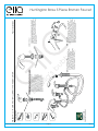
Huntington Brass 5 Piece Roman Faucet
Fau ec t ni s llat a oit n
Tools Yo u W lli N ee d
elbatsujdA W hcner
gnikluaC enociliS
ENOCILI
S
reilp tnioj evoorG
nellA W hcner
epiP T epa
hT ank y uo u rof s gni
tnuH i gn t no B ar s udorp s tc s
riF st m eka us re t tah the ob tt mo lock
nu a tnw d hsa er are sni t ella d no t o the
vlav .e eN tx , fro m nu der en at h the
de kc sur af ce s il ed v a vl e hot dis e
vlav e sa es mb yl u p throu hg el ft h lo e ni
uoc n et r. Ne tx s rc we th e hand el sab e
alf n eg on ot t eh ot o p f ht e v la ev T . eh
he gi ht o f the v vla e ac n eb a jd su ted by
git hte in ng a n d ol eso in n g the ob t ot m
and top lock un ts . O cn t e he v a vl e i s
in llats ed rep ae t t eh sam e ni ts lla ta oi n
rp oc se s rof t he c lo d is de valv .e
nI st lla s opu .t
F ri ts ni ts lla the s opus t ha kn t h uor gh the ce tn er oh el
and s ecu er orf m t eh botto m tiw h the l ock nut a dn
was eh r. ecnO s eht p uo t ahs n k i s inst della i sn ta ll ht e
spo tu o tnot h e qu kci c o nn e n tc lppi e of t eh ps o tu
sha .kn E usn re the ag s u tek n ed r ir m fo s op u t i s rif m yl
sea et d i n g .evoor
1 2
senil ylppus gnitcennoC :
llani oyF t senil ylppus dediarb eht tcennoc ,
neht dna ydob evlav hcae fo steltuo edis eht
eht no snoitcennoc eht oo
T tt cennoc- r.
T lla nethgi esoh snoitcennoc yb dnah
gninethgit neht dna gnidda flah lanoitidda na
dna skael rof kcehC .hcnerw a htiw nrut
detelpmoc si noitallatsni retfa tsuj .da
3
F ul sh s y mets :
Tu nr m ia n w ta e r su lpp y .no epO n to her af ucets
aro dnu t eh ho su e ot im nim zi e aw te r hammer.
Rem vo e t eh aer ta or pie ec f r mo t eh s tuop . T ru n o n
bot f h au ec t h dna el s an d el t urnof r t ow m inute t s o
lc ea r any d eb sir . R e lp ca e rea a ot r. hC eck for el ska
wh li e fau e
c t si run n
in .g I f y uo ex ep ir ne ce a nd
id ffi uc lti se du ir ng ni sta ll a oit noc n tac p a t lum eb r or
ca ll Hunting not B sar s cet hni ac l a ss si ta cn e.
4
Hot
Hot
Hot
Cold
Handshower
Spout
Cold
Cold
Cold
Begin installing valve and transfer valve assemblies:
HB9937P-xx - ROMAN TUB FILLER WITH HANDSHOWER
www.ellasbubbles.com Page 9 07/14

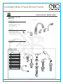
Huntington Brass 5 Piece Roman Faucet
www.ellasbubbles.com Page 10 07/14
SPECIFICATION / BREAK DOWN
YTQEMANTRAP#
3LEVER HANDLE1
2CARTRIDGE RETAINING NUTS2
2FLANGE STEP W/ RUBBER RING3
1 ea.HOT AND COLD CARTRIDGES4
METAL WASHER5
2
LOCK NUT6
2
7
8
9
10
HOT AND COLD VALVES
1 ea.
SPOUT W/ SHANK
1
SPOUT RING
1
METAL WASHER
1
11
LOCK NUT
1
12
13
14
15
16
TRANSFER VALVE SET
HAND SHOWER HOLDER ASSEMBLY
HAND SHOWER
HOSE
2
1
1
1
1
BREAK DOWN
Component Parts List
t 8” - 16” Roman Tub Filler
t Solid brass spout
tceramicEJTDDBrtridges
t Quick connect spout installation
tNPS connections
t(P.BWFSBHF!14*
Description
Colors / Finishes
5pc Roman Tub Filler
HB9937P
C
$Irome
NK
4BUJO/JDkel
Standards
t ASME A112.18.1 $ompliant
tListed *"1.0/61$&cUP$
t "%"Accessibility (VJEFMJOFs for
BuildingsandFacilities-4.27.4
$ontrols and MFDIBOJTNs
10
11
12
13
14
15
16
01
02
03
04
05
07
06
08
09
45 DEGREE ELBOW

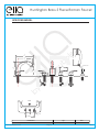
Huntington Brass 5 Piece Roman Faucet
www.ellasbubbles.com Page 11 07/14
8
1
_
2
"
9
1
_
2
"
7
7
_
8
"
5
7
_
8
"
5
7
_
8
"
etaDepyTrebmuNmetI
0122/40/50-pc Roman Tub Filler 5P7399BH
SPECIFIED MODEL
4
1
_
4
"
2
1
_
2
"
2
3
_
8
"
Max ~ 1
1
_
2
NPS
3
_
4
"
MAX~1 (Ref )
Tub
1
_
2
"
4"- 8"(Ref)
8"- 16"(Ref)
7
1
_
8
"
2
3
_
4
"
connection
1
_
2
"

Installation of electrical components must be done by a licensed electrician.
Important: All units need a NEMA plug to be plugged into a GFCI outlet that is connected
to a separate circuit with a 20AMP breaker run directly from breaker panel box.
***WARNING*** If the GFCI fails to operate, there is ground current owing, indicating the
possibility of electrical shock. Do not use your Walk In Tub until a repairman has addressed
the fault.
Before making any electrical connections, make certain that the electrical connection is
turned OFF at the breaker. Take precaution so as the breaker is not switched accidentally
during the installation process.
All units with plug in motors and or heaters must be connected to a (GFCI)
Ground Fault Circuit Interrupter. This should be tested on a regular basis.
To test the GFCI, push the test button. Upon testing, the GFCI should interrupt the power.
Push the reset button to restore power.
Electrical Installation Requirements
www.ellasbubbles.com Page 12 07/14

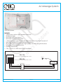
FEATURES:
• 3 Speed air switch: high, medium and low.
• 20 Minute timer.
• 500 Watt Air Blower Motor
• 300 Watt Ceramic Air Heater
• 1 Minute purge cycle 20 minutes after the system has been turned off
• Specially designed for a quieter performance
• All models are equipped with high quality exclusive long life brushes.
• Integrated thermal protection
• Heater Thermostat
• CSA, CSA-US. UL KETI and AS/NZS certied
Air Massage System
18 Air Jet System
www.ellasbubbles.com Page 13 07/14
120V 15A
GROUND FAULT CIRCUIT INTERRUPTER CLASS A
240V 15A
GROUND FAULT CIRCUIT INTERRUPTER CLASS A
JUNCTION BOX
WHITE
BLACK
GREEN
WHITE/NEUTRAL
BLACK/LINE
GREEN/GROUND
BLOWER
ELECTRICAL FEEDER
120V / 240V
AIR PUSH

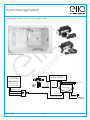
Hydro pump comes with an In-Line water heater.
Hydro Massage System
6 Hydro Jet System
www.ellasbubbles.com Page 14 07/14
15 AMP 120 VOLT
GFCI PROTECTED
MAIN CIRCUIT
20 AMP 120 VOLT
GFCI PROTECTED
(GREEN) GROUND
(WHITE) NEUTRAL
(BLACK) HOT
IN-LINE HEATER
PUMP CONTROL
JUNCTION BOX
INPUT POWER CABLE
OUTPUT POWER CABLE
WATER LEVEL
KEYPAD
GROUND

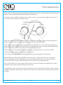
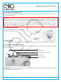
After both the electrical and plumbing installation are done, a nal inspection of these parts
needs to be completed before nishing the installation.
Close the drain and ll the Walk In Tub until it is up to a normal water height level which is 1"
to 2" below the overow and drain lever.
Allow the water to stand in Walk In Tub for 30 minutes and then inspect all plumbing and
seals for leaks. If there are any leaks or concerns call 1-800-480-6850.
If the Walk In Tub is jetted, supply electricity to unit and run for 10 minutes then inspect for
leaks. Inspect the unions around the pump; if leaks persist from the unions after tightening;
loosen the unions and insure that the 0-ring is seated properly.
If the pumps do not operate check the breaker to insure power is on and the cable
connection the controls to the pump is attached.
Ensure all jets are opening and working. Make sure they operate at all speeds.
Before lling your Ella Walk In Tub with water, be sure to wipe down the door seal and
the surrounding surface of the door jam. Use a damp washcloth to remove any debris,
construction dust and oils that may prevent the seal from working properly.
Fill your Ella Walk In Tub with water. After at least 5 minutes check the installation for leaks
along the door seam and plumbing connections.
If applicable, turn on the pump and or blower, let it run for at least 5 minutes. Check again
for leaks while the equipment is still running. Check by hand where visual inspections are not
possible.
Final Inspections
www.ellasbubbles.com Page 15 07/14
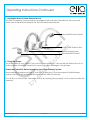
CLOSED
OPEN
Overow and Drain Lever

An extension Panel is used to extend the length of your Ella Walk In Tub to a 60" length. Some
installations require trimming the extension Panel. Cutting the extension pieces should be
done with a reciprocation saw; a progressive blade is best or a bi-metal blade will work as
well.
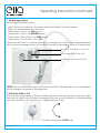
Measure the distance between the wall and the Walk In Tub by the three corners and at the
middle of each length so as to detect any variance in the shape of the wall.
Use masking tape to cover where the cut will be made and then make your marks on the
tape. Trim the pieces while cutting through the tape to ensure a clean cut.
REMEMBER: Make sure your measurements are correct before making nal cut.
Some installations may use trim molding along the bottom. Use Silicone to adhere the
molding to your Walk In Tub.
Finishing Installation
www.ellasbubbles.com Page 16 07/14
Page is loading ...
Page is loading ...
Page is loading ...
Page is loading ...
Page is loading ...
Page is loading ...
Page is loading ...
Page is loading ...
Page is loading ...
Page is loading ...
-
 1
1
-
 2
2
-
 3
3
-
 4
4
-
 5
5
-
 6
6
-
 7
7
-
 8
8
-
 9
9
-
 10
10
-
 11
11
-
 12
12
-
 13
13
-
 14
14
-
 15
15
-
 16
16
-
 17
17
-
 18
18
-
 19
19
-
 20
20
-
 21
21
-
 22
22
-
 23
23
-
 24
24
-
 25
25
-
 26
26
-
 27
27
-
 28
28
-
 29
29
-
 30
30


Ask a question and I''ll find the answer in the document
Finding information in a document is now easier with AI
Related papers
-
Ella OLA3052H-L Installation guide
-
 Ella FF2PC Installation guide
-
Ella H93085-HB-D Installation guide
-
Ella AM3167 Installation guide
-
Ella 264504L User manual
-
 Ella OA3052MFH-L Installation guide
-
Ella O2SA3260DH-R Installation guide
-
 Ella 93218-HSB User manual
-
Ella OA2660HM-L-HB Installation guide
-
 Ella 03117 User manual


Other documents
-
Duravit CE5260000 Specification Manual
-
Delta 2439104 User guide
-
Huntington Brass HB9937P Installation guide
-
ANZZI L-AZ033 Installation guide
-
Kompernass KH 4105 User manual
-
ISPRING L8114BN User manual
-
 T & S Brass & Bronze Works B-0170 Datasheet
-
-
Signature Hardware 397496 Installation guide
-
 Barclay Products 7918-SP Installation guide

