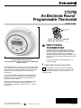
Honeywell An Electronic Round CT2700 is a programmable thermostat designed for convenient and energy-saving temperature control in your home. Its user-friendly features allow you to customize heating and cooling schedules that match your daily routine, helping you save energy and stay comfortable. With its simple installation process and compatibility with various systems, the CT2700 is an ideal choice for upgrading your home's temperature management system.
Honeywell An Electronic Round CT2700 is a programmable thermostat designed for convenient and energy-saving temperature control in your home. Its user-friendly features allow you to customize heating and cooling schedules that match your daily routine, helping you save energy and stay comfortable. With its simple installation process and compatibility with various systems, the CT2700 is an ideal choice for upgrading your home's temperature management system.


-
 1
1
-
 2
2
-
 3
3
-
 4
4
-
 5
5
-
 6
6
-
 7
7
-
 8
8


Honeywell An Electronic Round CT2700 is a programmable thermostat designed for convenient and energy-saving temperature control in your home. Its user-friendly features allow you to customize heating and cooling schedules that match your daily routine, helping you save energy and stay comfortable. With its simple installation process and compatibility with various systems, the CT2700 is an ideal choice for upgrading your home's temperature management system.
Ask a question and I''ll find the answer in the document
Finding information in a document is now easier with AI
Related papers
-
Honeywell T8400C User manual
-
Honeywell RTH110B User manual
-
-
Honeywell Honeywell/34 CT3455 User manual
-
-
Honeywell Thermostat CT3451 User manual
-
-
-
Honeywell Honeywell/20 CT2095 User manual
-
Other documents
-
ClimateMaster ATM11H03 Install Manual
-
 Hunter Fan 43320 Owner's manual
-
 Honeywell Home RTHL221B1008/K1 Installation guide
-
-
Air King AKEDT2 Operating instructions
-
Slant/Fin 101640F00 Specification
-
Leica Microsystems EM TP Application Note
-
Sevenoak SK-EBH01 User manual
-
-

