Page is loading ...

90+ High Efficiency Upflow/Downflow Models
M2 Series
Service Manual

2
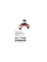
Typical meters used to service furnaces.
A. Differential Pressure Gauge
B. Volt-Ohm Meter
C. Manometer
D. Slant Gauge
A.
B.
C.
D.

3
Conversion continued
Completing The Conversion ...........................26
Electrical Wiring .......................................... 26-28
General .......................................................27
Line Voltage Wiring .......................................27
Low Voltage Wiring .................................. 27-28
Ventilation ................................................... 28-29
Start-Up And Adjustments ............................29-31
General ....................................................... 29
Start-Up Procedure .......................................29
Shut Down Procedure ...................................29
Verifying And Adjusting Firing Rate ............29-30
Verifying And Adjusting
Temperature Rise ...................................30
Verifying Burner Operation ............................ 30
Verifying Operation Of The Supply Air
Limit Switch ...................................... 30-31
System Operation Information ..................... 31-32
General ....................................................... 31
Sequence of Operation ........................... 31-32
Heating Mode .................................... 31-32
Cooling Mode .........................................32
Fan Mode ..............................................32
Furnace Fails To Operate ......................... 32-34
Component Parts .........................................32-46
Description of Components ........................... 32
Location of Major Components ................ 33-34
M2RC Upflow Furnace ........................... 33
M2RL Downflow Furnace ........................34
Troubleshooting Flow Chart ........................... 35
UTEC Control Board Sequence ......................36
Wiring Diagram .............................................37
Polarity and Ground ......................................38
Blower Door Switch ...................................... 38
Transformer .............................................38-39
Control Board .......................................... 39-40
High Limit Controls .......................................40
Main Air Limit Control ...............................40-41
Roll Out Limit Control ....................................41
Draft Inducer Motor .................................. 41-42
Pressure Switch ...................................... 42-44
Hot Surface Ignitor ....................................... 44
Gas Valve ...............................................44-46
Flame Sensor .............................................. 46
Heat Exchanger and Its Components .........46-47
Blower Performance .....................................46-47
Flue Gas Temperature ...................................... 47
Natural Gas Pipe & LP Gas Pipe
Capacity Table ...........................................47
Introduction .....................................................5-9
General .........................................................6
Clearances To Combustible Materials ...............6
Unit Dimensions ..........................................7-8
Model Identification Code ................................9
Circulating Air Supply ....................................9-10
General ......................................................... 9
Return Air Provisions ......................................9
Airflow Data ................................................. 10
Air Distribution Systems ...................................10
Upflow Furnace Installation ..............................10
Downflow Furnace Installation ..................... 10-15
Duct Connector Selection For Downflow
Models .................................................. 10
Installation Of The Duct Connector For
Downflow Installations .............................11
Cut Out Floor Opening For Downflow
Models ..............................................11-12
Cut Duct Opening .........................................11
Install Furnace Mounting Plate .................. 11-13
Install Duct Connector .............................. 11-14
Alternate Attachment Methods .................. 14-15
Install Downflow Furnace ...............................15
Venting and Combustion Air
Requirements ............................................... 15
General ........................................................15
Venting Requirements ..................................15-22
General ..................................................15-17
Vent Pipe Material ........................................17
Vent Pipe Length and Diameter ......................17
Vent Pipe Installation ............................... 17-22
Pipe Routing and Support ....................17-20
Pipe Couplings at the Furnace .............17-20
Location of Outdoor Terminations ........ 18-21
Horizontal Venting ..............................21-22
Vertical Venting ................................. 21-22
Vent Freezing Protection .........................22
Concentric Vent Termination ....................22
Drainage Of Condensate From Furnace ........ 22-23
Gas Supply And Piping ................................23-24
General ...................................................23-24
Leak Check ..................................................24
High Altitude Derate ......................................24
Conversion .................................................. 24-26
Pressure Gauge Installation ...........................26
Lighting And Adjustment Of The Appliance ..... 26
Adjusting The Manifold Pressure ....................26
TABLE OF CONTENTS
Page Page

4

5
INTRODUCTION
This service manual is designed to be used in conjunction with the installation manual
provided with each furnace.
This condensing furnace represents the very latest in high efficiency gas furnace technology.
Consequently, certain controls within the furnace consist of highly sophisticated electronic
components which are not user serviceable. Therefore, it is essential that only competent,
qualified service personnel attempt to install, service, or maintain this product.
This service manual was written to assist the professional HVAC service technician to
quickly and accurately diagnose and repair any malfunctions of this product.
This service manual covers both upflow models and downflow models installed as direct vent
model non-direct Vent applications. The overall operation of all these models is basically the
same with the exception of certain controls that are unique to a particular model.
This manual, therefore, will deal with all subjects in a general nature (I.E. all text will pertain
to all models) unless that subject is unique to a particular model or family, in which case it will
be so indicated.
It will be necessary then for you to accurately identify the unit you are servicing, so you may
be certain of the approved diagnosis and repair. (See Unit Identification on page 9.)
This manual was prepared by the senior Technical Service and Communication Departments.
!
WARNING:
The information contained in this manual is intended for use by a qualified service
technician who is familiar with the safety procedures required in installation and
repair and who is equipped with the proper tools and testing instruments.
Installations and repairs made by unqualified persons can result in hazards
subjecting the unqualified person making such repairs to the risk of injury or
electrical shock which can be serious or even fatal not only to them, but also to
persons being served by the equipment.
If you install or perform service on equipment, you must assume responsibility for
any bodily injury or property damage which may result to you or others. We will not
be responsible for any injury or property damage arising from improper installation,
service, and/or service procedures.

6
RIGHT
SIDE
RIGHT
SIDE
The heat exchanger is a tubular design made from aluminized
steel. The direct drive multi-speed blowers range from 1/3 to
3/4 hp to handle any air conditioning application up to 5 Tons.
See Figures 1 & 2 for overall dimensions.
CLEARANCES TO COMBUSTIBLE
MATERIALS
This furnace is designed for the minimum clearances to
combustible material listed in Table 1. Refer to the furnace
name plate, located inside the furnace cabinet, for specific
model number and clearance information.
GENERAL
The extra high efficiency upflow and downflow gas furnaces
may be installed free standing in a utility room, basement, or
enclosed in an alcove or closet. The extended flush jacket
provides a pleasing "appliance appearance" installation.
Design certified by the American Gas Association (AGA)
Laboratories and the Canadian Gas Association (CGA)
Laboratories. The product is truly designed with the contractor
and consumer in mind.
The M2R (C,L) Series covers all upflow and downflow
applications. The furnace uses hot surface ignition providing
AFUEs in the 90+ range from 40,000 to 120,000 Btuhs.
TOP
DOWNFLOW MODEL
TOP
LEFT
SIDE
BOTTOM
LEFT
SIDE
Furnace Cabinet Minimum Clearances (Inches)
Input Width Plenum Ductwork within
(Btuh) (Inches) Side Vent Back Top* Front** Surfaces 3 ft. of Furnace
80,000 19 3/4 0 0 0 10 0 1/4 1/4
100,000 19 3/4 0 0 0 10 0 1/4 1/4
Table 1. Minimum Clearances to Combustible Material.
BOTTOM
* For Downflow model only. Upflow models can be 1".
** 24 inches is the minimum clearance for servicing. 36 inches is the recommended clearance for service.
UPFLOW MODEL

7
7 7/8"
Bottom Return Opening
23"
19 3/4"
7/8" Dia. Electric
Connection
2 1/4"
43"
25 1/8"
25 1/4"
28"
25 1/4"
33"
Condensate
Drain Outlet
Combustion
Air Inlet
1 1/2" x 3 1/2" Dia.
Opening for
Gas Connection
+
1 1/2" x 3 1/2" Dia.
Opening for
Gas Connection
Bottom Return
Opening
17"
Exhaust
Vent
25 5/8"
20 1/2"
20"
20 3/4"
+
7/8" Dia. Electric
Connection
23 1/4"
22 1/2"
Exhaust Vent
30 1/4"
8"
8"
1 1/4"
27 5/8"
20"
19 3/4"
Combustion Air
Inlet
19 1/2"
18 1/4"
3/4"
1/2"
3/4"
6 1/4"
A/C Coil Box
3/4" 3/4"
3/4"
L
C
L
C
Cover
Plate
Condensate
Drain Outlet
2 1/4"
1 3/8"
Upflow Furnace
UNIT DIMENSIONS
Figure 1. M2RC Unit Dimensions
080C 80,000 19 3/4 18 1/4 7 7/8 17 1/4 172
100C 100,000 19 3/4 18 1/4 7 7/8 17 1/4 180
AB
Dimensions (inches)
Furnace
Btuh
CD
Shipping
Weight
(lbs)
Model
Number
M2RC-

8
3/4"
3/4"
2 1/2"
L
C
L
C
19 3/4"
10"
18 1/4"
Condensate
Drain
Outlet
7/8" Dia.
Electric
Connection
1 1/2" x 2 1/2"
Knockout
For Gas
Connection
27 7/8"
19 3/4"
7/8" Dia. Electric
Connection
24 1/2"
3/4"
43"
21 7/8"
21 1/2"
15 1/2"
21 1/2"
10 1/4"
Bottom Supply Air
Opening
(Side)
Exhaust
Vent
2"
1 1/2" x 3 1/2" Dia.
Opening for
Gas Connection
3/4"
22 1/2"
Exhaust Vent
Combustion Air Inlet
24 7/8"
24 7/8"
21 7/8"
21 1/4"
8"
20"
20 3/4"
19 3/4"
6 1/4"
20"
20 3/4"
A/C Coil Box
Bottom Supply Air Opening
18 1/4"
Bottom Supply Air Opening
Return Air Opening
Condensate
Drain Outlet
Combustion
Air Inlet
19 3/4"
080C 80,000 19 3/4 18 1/4 10 18 1/4 174
100C 100,000 19 3/4 18 1/4 10 18 1/4 185
AB
Dimensions (inches)
Furnace
Btuh
CD
Shipping
Weight
(lbs)
Model
Number
M2RL-
Downflow Furnace
UNIT DIMENSIONS Continued
Figure 2. M2RL Unit Dimensions

9
M 2 RC - 080 A - 16 - B N
MODEL IDENTIFICATION CODE
Cabinet Width
B - 19-3/4"
Application
M-Manufactured Home
Furnace Series
Comfort Model
RC - Condensing Upflow
RL - Condensing Downflow
Airflow
16 - 1600 CFM
Electrical Code
A - 1PH, 60 Hz, 120 VAC
Heating Capacity
Input, BTUH (000’)
Fuel Type
N - Natural
Gas Ready
L - Propane (LP)
Gas Ready
!
WARNING:
Products of combustion must not be allowed to
enter the return air openings of the furnace or the
circulating air supply. Failure to prevent products
of combustion from being circulated into the living
space can create potentially hazardous conditions
including carbon monoxide poisoning that could
result in personal injury or death.
The floor or platform on which the furnace is
mounted must provide sound physical support of
the furnace with no gaps, cracks, or sagging
between the furnace and the floor or platform.
The circulating air ductwork must not be connected
to any other heat producing device such as a
fireplace insert, stove, etc.
CIRCULATING AIR SUPPLY
General
Plenums and air ducts must be installed in accordance with
the Standard for the Installation of Air Conditioning and
Ventilating Systems (NFPA No. 90A) or the Standard for the
Installation of Warm Air Heating and Air Conditioning Systems
(NFPA No. 90B).
RETURN AIR PROVISIONS
Upflow models draw the return air from the base of the
furnace. A stand or return air duct must be supplied to the
furnace to provide the required return air.
Downflow models draw the return air from the top of the
furnace. The minimum required clearance to the top of the
furnace is detailed on the furnace rating plate. Additional
clearance may be required depending upon filter accessibility.
For each application, the U.S.A. home manufacturer shall
comply with all of the following conditions to have acceptable
return air systems for closet installed forced air heating
appliances:
a. Regardless of the location, the return air opening into
the closet shall not be less than specified in the
appliance’s listing.
b. Means shall be provided to prevent inadvertent closure
by a flat object placed over the return air opening when
it is located in the floor of the closet (versus the vertical
front or side wall).
c. The cross-sectional area of the return duct system
leading into the closet shall not be less than 390 square
inches.
d. The total free area of openings in the floor or ceiling
registers serving the return air duct system must be at
least 352 sq. in. At least one register should be located
where it is not likely to be covered by carpeting, boxes
and other objects.
e. Materials located in the return duct system must have
a flame spread classification of 200 or less. This
includes a closet door if the furnace is in a closet.
f. Noncombustible pans having 1" upturned flanges are
located beneath openings in a floor duct system.
g. Wiring materials located in the return duct system shall
conform to Articles 300-22 of the National Electrical
Code (ANSI C1/NFPA-70).
h. Gas piping is not run in or through the return duct
system.
i. Test the negative pressure in the closet with the air-
circulating fan operating at high speed and the closet
closed. The negative pressure is to be no more
negative than minus 0.05 inch water column.
j. For floor return systems, the manufactured home
manufacturer shall affix a prominent marking on or near
the appliance where it can be easily read when the
closet door is open. The marking shall read:
!
CAUTION:
HAZARD OF ASPHYXIATION: Do not cover or
restrict return air opening.
k. Air conditioning systems may require more duct, register
and open louver area to obtain necessary airflow. Use
NORDYNE’s certiduct program to determine proper
duct size for A/C.
Table 2 shows the airflow data for each furnace model.

10
Furnace External Static Pressure (Inches Water Column)
Furnace Input Motor Motor 0.1 0.2 0.3 0.4 0.5
Model No. Btuh Speed HP CFM Rise CFM Rise CFM Rise CFM Rise CFM Rise
High * 1840 - 1780 - 1700 - 1630 - 1550 -
Med-High 1600 43 1560 44 1470 47 1400 49 1350 51
Med-Low ** 1380 50 1350 51 1300 53 1250 55 1190 58
Low 1100 - 1050 - 1000 - 950 - 900 -
High * 1910 - 1860 - 1780 - 1700 - 1620 -
Med-High ** 1640 53 1620 54 1540 57 1480 59 1420 62
Med-Low 1440 61 1410 62 1370 64 1320 66 1270 70
Low 1230 - 1210 - 1180 - 1140 - 1090 -
High * 1620 43 1560 45 1490 47 1430 49 1365 52
Med High 1450 49 1400 50 1350 52 1295 54 1240 57
Med Low ** 1255 56 1225 57 1180 60 1145 61 1105 64
Low 1080 65 1055 67 1030 68 1000 70 960 73
High * 1620 54 1555 57 1485 59 1425 62 1355 65
Med High ** 1430 62 1375 64 1330 66 1265 70 1210 73
Med Low 1260 70 1220 72 1170 75 1130 - 1070 -
Low 1085 - 1050 - 1015 - 970 - 935 -
80,000
100,000
M2RL-080
M2RL-100
1/2
1/2
1/2
1/2
M2RC-080
M2RC-100 100,000
80,000
CAPACITIES — Furnace Airflow Data
Table 2. Furnace Airflow Data
* Factory wired cooling speed tap **Factory wired heating speed tap -Not Recommended
NOTE: Data is for operation with filter.
AIR DISTRIBUTION SYSTEMS
For proper air distribution, the supply duct system must be
designed so that the static pressure measured external to
the furnace does not exceed the listed static pressure rating
shown on the furnace rating plate.
Three typical distribution systems are illustrated in Figure 3.
Location, size, and number of registers should be selected
on the basis of best air distribution and floor plan of the home.
UPFLOW FURNACE INSTALLATION
a. Position the furnace on top of the return air ductwork or
return air stand.
A Single trunk duct
B
Dual trunk duct
w/crossover connector
C
Transition duct
w/branches
Figure 3. Typical Supply Duct System
NOTE: The ductwork or stand must have an opening
equal to that of the return air opening of the furnace.
Refer to Figures 1 & 2 for the proper return air opening
size.
Secure the furnace to the floor or base once it has been
properly positioned.
b. Position and secure the A/C coil box to the top of the
furnace. The A/C coil box can be secured to the furnace
using the provided attachment brackets. These brackets
are designed to attach the furnace cabinet to the A/C
coil box on the sides. To install these brackets, position
one bracket on the side of the furnace, so that the
locating dimples are in the groove created by the top of
the furnace cabinet and the bottom of the A/C coil box.
Using the provided self-drilling screws, secure the
bracket to the A/C coil box and the furnace. Repeat on
the other side of the furnace for the other bracket.
c. Attach the plenum from the supply duct to the flanges
of the A/C coil box.
d. Secure the plenum to the supply ductwork.
NOTE: Additional fasteners may be used at rear, sides or
through door frame, as desired, to secure furnace to closet
or alcove framing.
DOWNFLOW FURNACE INSTALLATION
DUCT CONNECTOR SELECTION FOR DOWNFLOW
MODELS
a. Determine depth of floor cavity from surface of floor to
top of supply air duct (See Figure 4).
b. Select appropriate model from Table 3 which matches
X-dimension of the floor cavity. To maximize air delivery,
remove reducer “C” (see Figure 6) to obtain the largest
open area that will fit the duct/floor construction.

11
If "X"
(Floor cavity) is:
7/8" (22mm) 901987
2" (51mm) 901988
4 1/4" (108mm) 901989
6 1/4" (159mm) 901990
8 1/4" (210mm) 901991
10 1/4" (260mm) 901992
12 1/4" (311mm) 901993
Use Duct
Connector Model
Table 3. Duct Connectors
x
SUPPLY AIR DUCT
FLOOR CAVITY
(depth equal to "X" in Figure 5 and Table 5)
Figure 4. Floor Cavity Cut-Out
13 1/4"
10 1/4"
19”
19"
T
Figure 5. Top View of Duct Connector
Figure 6. Duct Connector
X
SEE
TABLE 5
REDUCER
FELT-SEAL
SPACERS
C
OPENING TO DUCT
WITH PLATE (C) REMOVED
OPENING BECOMES
13-1/4” x 13-1/4”
b. Center duct connector and push back against rear
edge of floor opening.
c. Mark cut-out location (tab area) and remove duct
connector.
d. Cut out duct opening 1/4" larger than area marked.
INSTALL FURNACE MOUNTING PLATE
a. Bend tabs on furnace mounting plate upwards 90°
b. Place mounting plate (supplied within duct connector)
at rear of the floor opening (See Figure 9).
INSTALL DUCT CONNECTOR
a. Place duct connector through the floor opening with
bottom tabs extending through the duct opening. (See
Figure 10)
b. Secure duct connector to floor.
c. Bend bottom tabs under and up tightly against the supply
air duct (See Figure 11).
FLOOR CAVITY
(depth equal to "X" in Figure 6 and Table 3)
SEE
TABLE 3
INSTALLATION OF THE DUCT CONNECTOR FOR
DOWNFLOW INSTALLATIONS
Required cut-out openings in the floor, ceiling, roof, and/or
walls must be carefully located to avoid misalignment of the
furnace, combustion air piping, and vent piping (see Figures
15-17 on pages 19 & 20). Installation procedures are
suggested for typical furnace installations and need not be
followed in the exact listed sequence.
CUT OUT FLOOR OPENING FOR
DOWNFLOW MODELS
a. Determine center of closet or alcove (Figure 8).
b. Locate center of the floor opening, measured 10" from
the rear wall, and mark cut-out measuring approximately
14-1/2" by 14-1/2" (± 1”) for model duct connector used
(refer to Figures 7 & 8).
CUT DUCT OPENING
a. Place duct connector through the floor opening with
bottom tabs resting on top of the supply air duct.

12
10"
FLOOR
OPENING
C
L
C
L
SIDE WALL
REAR WALL
FUEL LINE
HOLE
25 1/8" (Upflow Models)
21 7/8" (Downflow Models)
Figure 8. Closet or Alcove Floor Cut-Out
Figure 7. Cut-Out Locations
25 1/8" (Upflow Models)
21 7/8" (Downflow Models)
FLOOR CUT-OUT
FOR DUCT CONN.
C
L
C
L
14-1/2"
2-1/4"
2-3/4"
20"
14-1/2"
13-1/2"
CASED COIL WRAPPER OUTLINE
REAR WALL OF CLOSET OR ALCOVE
Fuel
Line
Hole
Alt. Fuel
Line Hole
25 1/8" (Upflow Models)
21 7/8" (Downflow Models)

13
REAR WALL
SUPPLY AIR DUCT
ALT.
FUEL
LINE
HOLE
MOUNTING
PLATE
FLOOR
OPENING
BEND CONNECTOR TABS
UNDER DUCT OPENING
FUEL
LINE
HOLE
REAR WALL
MOUNTING
PLATE
FLOOR
OPENING
FUEL
LINE
HOLE
SUPPLY AIR DUCT
CUT DUCT OPENING
1/16TH. LARGER THAN
DUCT CONNECTOR
ALT.
FUEL
LINE
HOLE
Figure 10. Duct Connector
Figure 9. Mounting Plate

14
TABS TABS
DUCT DUCT
1. INSERT DUCT PLENUM CONNECTOR
INTO DUCT CUT-OUT.
2. BEND BOTTOM TABS OVER
AND ONTO THE UNDERNEATH
DUCT SERVICE.
Figure 11. Installation of Duct Connector
Duct
Duct Connector
Narrow Duct
Figure 12. Narrow Duct Installation
Figure 13. Alternate Installation
Staple Folded Duct
Flap (typ) to side of Duct
Connector
Duct
STEP 4.
STEP 1.
"A" "A"
"B"
"B"
Cut- Out
Area"A"
Cut- Out
Area "A"
Fold Back Flap "B"
Fold Back Flap "B"
Top of Duct
"A" "A"
STEP 2.
"B"
"B"
Fold Back Flap"B"
Cut
Lines Duct
Fold Back Flap"B"
STEP 3.
Bend Duct Connector Tabs Up
and Over- (along length of duct)
Duct
Flap "B"
Duct
This procedure may also be used to install a furnace duct
connector to narrow metal ductwork where insufficient
clearance prevents bending of the duct connector tabs at the
side(s) of the duct. (See Figure 13).
ALTERNATE ATTACHMENT METHODS
NOTE: The duct connector is designed for use on ducts 12"
in width. When using the connector on 12" wide ducts, there
may be insufficient clearance to bend the tabs on two sides
of the duct connector. In such cases the tabs may be
attached to the sides of the duct by using sheet metal
screws or other suitable fasteners. (See Figure 12).
If tape is used to provide a better seal, it should be approved
by applicable national or local codes.

15
1. Score and cut the top of the metal duct as indicated in
Step 1 or Step 2. With Step 1 choice, also cut out the
metal from the shaded area “A”.
2. Fold the duct flap “B” up, (See Step 3).
3. At the front-to-back of duct run (Area “A”), bend the duct
tabs and secure them directly to the duct.
4. At area “B”, bend the duct tabs up and back over, around
the duct connector, (See Step 3).
5. Fold/form the duct flap against the side of the duct
connector and attach as shown, (See Step 4). Use three
(3) staples (minimum) on each duct flap OR, if a 2X
block/joist is not provided, use two (2) sheet metal
screws (minimum) on each duct flap. An alternate
attachment method is acceptable, as long as the plenum
is securely attached.
6. Tape the duct flap edges with an approved tape for a
leak-free joint.
INSTALL DOWNFLOW FURNACE
a. Prepare the A/C coil box as described in the instructions
provided with the coil box.
b. Place A/C coil box onto duct connector.
c. Slide A/C coil box back until it is firmly against the
mounting plate. Mounting plate tabs should be bent
upwards so as not to interfere with furnace.
d. Secure front with one (1) fastener at each corner
through front bottom flange and through the back of the
A/C coil box.
e. Position the furnace on top of the A/C coil box. Ensure
that the furnace is properly positioned on the wrapper.
f. Secure the A/C coil box to the bottom of the furnace.
The A/C coil box can be secured to the furnace using
the provided attachment brackets. These brackets are
designed to attach the furnace cabinet to the A/C coil
box on the sides. To install these brackets, position
one bracket on the side of the furnace, so that the
locating dimples are in the groove created by the
bottom of the furnace cabinet and the top of the A/C coil
box. Using the provided self-drilling screws, secure the
bracket to the A/C coil box and to the furnace. Repeat
on the other side of the furnace for the other bracket.
NOTE: Additional fasteners may be used at rear, sides or
through door frame, as desired, to secure furnace to closet
or alcove framing.
VENTING AND COMBUSTION AIR
REQUIREMENTS
!
CAUTION:
Snow must not be allowed to restrict or block the
combustion air intake or vent pipes.
General
NORDYNE condensing furnaces must be installed with
outdoor combustion air piped directly to the furnace. Codes
refer to this type of installation as direct vent, or two pipe
installation.
Provisions must be made for adequate supply of air for
combustion and ventilation. For United States installations,
the adequacy of air provisions can be determined by
consulting the current version of the National Fuel Gas Code
(ANSI Z223.1/NPFA-54). For Canadian installations,
requirements are specified in the National Standard of
Canada (CAN/CGA B149.1 & .2). Consult local codes for
special requirements.
NOTE: If the furnace is operated without adequate air for
combustion and ventilation, it may not perform properly.
Furnace components may be strained by high temperature
and could fail prematurely.
!
WARNING:
The combustion air piping must not be blocked or
restricted in any manner.
!
WARNING:
Furnace installation using methods other than
those described in the following sections must
comply with the National Fuel Gas Code and all
applicable local codes to provide sufficient
combustion air for the furnace.
VENTING REQUIREMENTS
!
WARNING:
FURNACE MUST NOT BE COMMON VENTED
WITH OTHER APPLIANCES.
General
This section specifies installation requirements for 2-pipe
combustion air piping. The capacity table provided in this
section applies to the total sum of vent and combustion air
piping lengths.
These condensing furnaces are classified as "Category IV"
appliances, which require special venting materials and
installation procedures. Category IV appliances operate with
positive vent pressure and therefore require vent systems
which are thoroughly sealed. They also produce combustion
condensate, which is slightly acidic and can cause severe
corrosion of ordinary venting materials. Furnace operation
can be adversely affected by restrictive vent and combustion
air piping. Therefore,
vent and combustion air piping lengths
must conform completely to the requirements of Table 4.
The furnace must be vented to the outdoors. It must not be
vented in common with any other appliance, even if that

16
f. After it has been determined that each appliance
connected to the venting system properly vents when
tested as outlined above, return doors, windows, exhaust
fans, fireplace dampers and any other gas burning
appliance to their previous conditions of use.
g. If improper venting is observed during any of the above
tests, the venting system must be corrected.
Procéder comme suit pour chaque appareil raccordé à la
tuyauterie d'évacuation et en état normal de fonctionnement;
tous les autres appareils raccordés à la même tuyauterie
d'évacuation doivent être mis hors service:
a. sceller toute ouverture non utilisée de la tuyauterie
d'évacuation
b. s'assurer que la tuyauterie d'évacuation présente des
dimensions et une pente horizontale conformes à la
norme ANSI Z223.1, intitulée National Fuel Gas Code
ou aux codes d'installation CAN/CGA B149, ainsi
qu'aux présentes instructions. S'assurer que la
tuyauterie n'est pas bloquée, restreinte, corrodée, qu'elle
ne fuit pas et qu'elle ne présente aucun autre défaut
potentiellement dangereux.
c. dans la mesure du possible, fermer toutes les portes et
fenêtres du bâtiment, et toutes les portes entre la pièce
où se trouve l'appareil raccordé à la tuyauterie
d'évacuation et les autres pièces du bâtiment. Mettre
en service les séccheuses et tout autre appareil qui
n'est pas raccordé à la tuyauterie d'évacuation. Faire
fonctionner à régime maximal tout ventilateur
d'évacuation, tel que les hottes de cuisinière et les
ventilateurs de salles de bains. Ne pas mettre en
service les ventilateurs d'été. Fermer les registres des
foyers.
d. respecter les instructions d'allumage. Mettre en service
l'appareil à l'essai. Régler le thermostat de manière à
ce que l'appareil fonctionne sans interruption.
appliance is of the condensing type. Common venting can
result in severe corrosion of other appliances or their venting
and can allow combustion gases to escape through such
appliances or vents. Do not vent the furnace to a fireplace
chimney or building chase.
If removing an existing furnace in a venting system, the
venting system may not be properly sized. To test the vent
system with the remaining appliances, follow the test outlined
below.
The following steps shall be followed with each appliance
connected to the venting system place in operation, while any
other appliances connected to the venting system are not in
operation:
a. Seal any unused openings in the venting system
b. Inspect the venting system for proper size and horizontal
pitch, as required in the National Fuel Gas Code, ANSI
Z223.1 or the CAN/CGA B149 Installation Codes and
these instructions. Determine that there is no blockage
or restriction, leakage, corrosion and other deficiencies
which could cause an unsafe condition.
c. In so far as is practical, close all building doors and
windows and all doors between the space in which the
appliance(s) connected to the venting system are
located and other spaces of the building. Turn on
clothes dryers and any other appliance not connected
to the venting system. Turn on any exhaust fans, such
as range hoods and bathroom exhausts, so they shall
operate at maximum speed. Do not operate a summer
exhaust fan. Close fireplace dampers.
d. Follow the lighting instructions. Place the appliance
being inspected in operation. Adjust thermostat so
appliance shall operate continuously.
e. Test for draft hood equipped appliance spillage at the
draft hood relief opening after 5 minutes of main burner
operation. Use the flame of a match or candle.
DIRECT VENT, DUAL PIPE LENGTH (ft.)
APPLICATION with two long radius elbows -
one on each pipe.*
PVC,CPVC or ABS Inlet/Outlet
SCH. 40 Pipe Size 3" 3"
90 90
90 90
Models M2RC,
M2RL - 080
Models M2RC,
M2RL - 100
1. Subtract 3.5 ft. for each additional 3" elbow.
2. Two 45 degree elbows are equivalent to one 90 degree elbow.
3. One short radius elbow is equivalent to two long radius elbows.
4. Do not include termination elbows in calculation of vent length.
5. This table is applicable for elevations from sea level to 2000 ft. For higher elevations, decrease
vent pipe lengths by 8% per 1000 ft. of altitude.
6. Only the above pipe materials are approved for use with these condensing furnaces.
Table 4. Vent Table
*NOTES

17
Condensing furnace combustion products have very little
buoyancy, so Table 4 is to be used without consideration of
any vertical rise in the piping.
NOTE: Always use the same or larger size piping for
combustion air as is used for the exhaust vent.
Vent Pipe Installation
Pipe Routing and Support
Route piping as directly as possible between the furnace and
the outdoors and remember that routing affects pipe size
requirements per the preceding section. If a two pipe system
is used, locate the combustion air intake and the vent
exhaust in the same atmospheric pressure zone - i.e. both
must exit the building through the same portion of exterior
wall or roof. Vent piping must be sloped upwards not less than
1/4" per foot in the direction from the furnace to the terminal.
This is to ensure that any condensate flows back to the
furnace (where it can be disposed of through the condensate
disposal system).
!
CAUTION:
Combustion air must not be drawn from a corrosive
atmosphere.
The quality of outdoor air must also be considered. Be sure
that the combustion air intake is not located near a source
of solvent fumes or other chemicals which can cause
corrosion of the furnace combustion system.
Piping must be mechanically supported so that its weight
does not bear on the furnace. Supports must be at intervals
no greater than five feet, and at smaller intervals if necessary
to ensure that there are no sagging sections to trap water
(See Figures 15 & 16).
Figure 17 illustrates vent and combustion air pipe sizes
exiting the furnace. Transition to the correct pipe size must
be done close to the furnace so that the full length of pipe is
of proper size.
These condensing furnaces have been certified for installation
with zero clearance between vent piping and combustible
surfaces. However, it is good practice to allow space for
convenience in installation and service.
Pipe Couplings at the Furnace
The provided rubber couplings should be installed in the
combustion air (3” diameter) and vent (2” diameter) pipes to
allow for servicing. These couplings are designed to fit
snugly over the pipe and be secured to the pipes using the
provided hose clamps. Refer to figures 15 and 16 for the
proper installation of these couplings.
e. S'assurer qu'un appareil muni d'un coupe-tirage ne
présente aucune fuite à l'ouverture du coupe-tirage
après que le brûleur principal ait fonctionné pendant
cinq minutes. Employer la flamme d'une allumette ou
d'une chandelle.
f. Après avoir déterminé que tous les appareils raccordés
à la tuyauterie d'évacuation évacuent correctment tel
que prescrit ci-dessus, rouvrir les portes et les fenêtres
et remettre les ventilateurs d'évacuation, les registres
de foyers et tout autre appareil fonctionnant au gaz
àleur état de fonctionnement initial.
g. Si un appareil n'évacue pas correctement à la suite de
l'un des essais ci-dessus, corriger la tuyauterie
d'évacuation.
Vent Pipe Material
Vent and combustion air pipe and fittings must be one of the
following materials and must conform to the indicated ANSI/
ASTM standards:
Material Standard
Schedule 40 PVC D1785
PVC-DWV D2665
SDR-21 D2241
& SDR-26
ABS-DWV D2661
Schedule 40 ABS F628
Cement and primer must conform to ATSM Standard D2564
for PVC and Standard D2235 for ABS. When joining PVC
piping to ABS, use PVC solvent cement. (See procedure
specified in ASTM Standard D3138.)
Vent Pipe Length and Diameter
In order for the furnace to operate properly, the combustion
air and vent piping must not be excessively restrictive. To
ensure this use Table 4, which indicates the maximum
allowable piping length for a furnace of specified input rate,
when installed with piping of a selected diameter and number
of elbows. This table applies to the length and number of
elbows for each pipe. To use the table, the furnace input
rate, the centerline length and the number of elbows on each
pipe must be known. Choose the diameter for which the
tabulated length is equal or greater than required.
Use of the table is illustrated in the following example:
Example:
An 80,000 Btuh furnace is to be installed in a "two-pipe"
system with 40 feet of vent piping. There are four elbows,
excluding those exterior to the building.
Solution:
Consulting Table 4, in the dual pipe length column for an
80,000 Btuh furnace, the maximum allowable length for
a 3" inlet/3" outlet is 90 feet with one elbow. Select 3"
pipe. For two additional elbows, deduct 3.5 ft. for each
elbow, or 7.0 ft. for a maximum installed vent length of
83 ft.

18
4 ft. min
12 in. min
12 in. min
12 in. min
9 in.
4 ft. min
12 in. min
12 in. min
Mechanical
draft vent
terminal
Direct vent
terminal
50,000 Btuh
or less
Forced
Air Inlet
Direct vent
terminal -
more than
50,000 Btuh
Mechanical
draft vent
terminal
Mechanical
draft vent
terminal
Grade
Less
than 10 ft.
3 ft. min.
Figure 14. Vent Termination Clearances
regulator and any relief equipment. These distances
apply ONLY to U.S. installations. In Canada, the
Canadian Fuel Gas Code takes precedence.
5. Avoid areas where condensate drainage may cause
problems by dropping on planters or patios, etc. Also
ensure that exhaust gases will not impinge on windows
or building surfaces, which may be compromised or
damaged by condensation. Do not install the vent
terminal such that exhaust is directed into window wells,
stairwells, under decks or into alcoves or similar
recessed areas, and do not terminate above any public
walkways.
6. Select the point of wall penetration where the minimum
1/4 inch per foot of slope up can be maintained.
!
CAUTION:
For optimal performance vent furnace through
wall which experiences the least exposure to winter
winds.
Location of Outdoor Terminations
Vent and combustion air intake terminations must be
located to ensure proper furnace operation and to conform
to applicable codes. Figure 14 illustrates necessary
distances from the vent termination to windows and
building air intakes. In Canada, the Canadian Fuel Gas
Code takes precedence over these instructions.
Specifically, all minimum distance requirements with
respect to termination of the vent piping listed below.
The following list is a summary of vent terminal location
requirements:
1. The termination must be 12 inches above snow level or
grade level whichever is higher. See Figure 18 for
alternate method to achieve 12" above snow level.
2. The minimum distance for a direct vent (2-pipe)
installation) from any door, (openable) window, or air
gravity inlet is 1 ft. below, 1 ft. horizontally, or 1 ft. above.
3. The vent termination shall be a minimum of 3 ft. above any
forced air inlet within 10 ft.
4. The vent termination shall be located at least 4 ft.
horizontally from any electric meter, gas meter,

19
5/8"
Inlet Exhaust
Top View
Combustion
Air Inlet
Offset with Exhaust
Pipe for Adequate
Dimensional Clearance
PVC or ABS
Pipe
Exhaust Vent
First Support, located as
close to furnace as possible
Rubber Coupling
w/ 2 Clamps
3" Coupling
A/C Coil
Box
Furnace
See Vent Table
Straps or other suitable
supports at minimum 5 foot intervals
Upward Pitch - 1/4" per Foot
Outlet Exhaust Vent
Coupling
Seal/Cualk
around pipe
at building
90˚ Elbow
12"
Min.
7"
Wall
Normal Snow Level
Upflow Furnace
Seal/Caulk
Around Pipe
at Building
90˚ Elbow
12"
Min.
Normal Snow Level
Wall
Coupling
First Support Should be as Close to
Furnace Connection as Possible
Exhaust Vent
Furnace
Rubber
Coupling
and 2
Clamps
PVC or
ABS pipe
Offset with Exhaust
Pipe for Adequate
Dimensional Clearance
Combustion
Air Inlet
5/8"
Inlet
Exhaust
See Vent Table 4
Straps or Other Suitable
Supports at Minimum of
5 ft. Intervals
Upward Pitch - 1/4" Per Foot
Outlet Exhaust Vent
Top View
Downflow Furnace
Figure 15. Horizontal Venting

20
Rubber
Coupling
w/ 2 Clamps
3" Coupling
A/C Coil
Box
Furnace Front
Furnace
Rubber
Coupling
w/ 2 Clamps
Support System
on Vertical Rise
Below Joints
Exhaust Vent
Support System with first support
as close to the furnace as possible
Upward Pitch
1/4" per foot
Combustion
Air Pipe
5'
Furnace
Rubber
Coupling
w/ 2 Clamps
Exhaust
Vent
Combustion
Air Pipe
Support System
on Vertical Rise
Below Joints
Support System with first support
as close to the furnace as possible
5'
Upward Pitch
1/4" per Foot
Upflow Furnace
Downflow Furnace
Combustion Air Inlet Pipe Collar
Diameter 3" for coupling or reducer
Furnace Top
2" PVC
Exhaust Vent
All Models
Figure 16. Vertical Venting
Downflow Furnace
Use appropriate adaptor for connection to furnace.
Upflow Furnace
Figure 17. Furnace Pipe Adaptions
Use appropriate adaptor for connection to furnace.
Combustion Air Inlet
3" PVC on 080/100 models
2" PVC
Exhaust Vent
All Models
Furnace Top
/