
Electrical
requirements
Electrical Shock Hazard
Electrical ground is required.
Do Not ground to a gas supply pipe.
Do Not change the power supply
cord plug. If it does not fit the outlet,
have a proper outlet installed by a
qualified electrician.
Do Not have a fuse in the neutral or
grounding circuit.
Check with a qualified electrician if
you are not sure the ice maker is
properly grounded.
Electrical wiring, water supply line
and drain line must not contact any
exposed terminals of the ice maker
wiring.
Failure to follow these instructions
could result in death or serious injury.
If codes permit and a separate ground-
ing wire is used, it is recommended that
a qualified electrician determine that
the grounding pafh is adequate.
A 120-volt, 60-Hz, AC-only, 15 or
20-ampere, fused, electrical supply is
required. Time-delay fuse or circuit
breaker is recommended. It is
recommended that a separate circuit
serving only this ice maker be provided
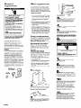
Recommended grounded
method
For your personal safety, this appliance
must be grounded. This appliance is
equipped with a power supply cord
having a 3-prong grounding plug. To
minimize possible shock hazard, the
cord must be plugged into a mating
3-prong grounding-type wall
receptacle, grounded in accordance
with National Electrical Code,
ANSl/NFPA 70-latest edition (* see Panel
A) and all local codes and ordinances.
If 0 mating wall receptacle is not
available, it is the personal responsibility
and obligation of the customer to have
a properly grounded, three-prong wall
receptacle installed by a qualified
electrician.
3-prong
Water requirements
The cold water line to the ice maker
must be l/4” O.D. soft copper tubing.
Use the threaded compression fitting to
connect the water line to the ice maker
inlet valve. Install a shutoff valve in the
water line where it can be easy to access
Preparation steps:
1 a Put on safety glasses and gloves.
2. Cut a l/2” minimum hole in cabinet
wall or floor for water line. Right side
of wall is easiest location.
3. Rough water supply tubing from the
cold water supply line to cabinet
opening.
4. Place water supply tubing in center of
the opening and allow enough
tubing so that it extends beyond the
cabinet front.
5. Install a manual shutoff valve in the
water line where it can be easily used,
6. Flush the water line into a bucket to
get rid of any particles that may clog
the inlet valve. Check that there are
no sharp bends or kinks in water line
that could restrict water flow. Turn the
shutoff valve to the “OFF” position.
Drain requirements
This appliance is equipped with a gravity
drain and a 4” long, 5/8” I.D. rubber drain
tube. Determine which type of drain
method you need and follow
preparation instructions for that method.
Recommended drain method
Install a l-l /4” minimum diameter
standpipe directly below the drain tube
outlet. (See Panel A for dimensions.)
Insulate the drain line up to the drain
inlet to minimize condensation on the
drain tube.
Alternate drain method
If a drain connection directly below the
drain tube outlet is not available, install
a drain pump in the rear compartment
of the ice maker. The drain pump must
meet these specifications:
l
It must be U.L.-listed and have a U.L.-
listed, 120 VAC, 3-wire, grounded
power supply cord.
l
Overall maximum outside dimensions:
15” wide x 6” deep x 9-l /2” high.
l
Minimum pump flow rate: 24 gallons
per hour (0.4 gallons per minute) at
12 feet lift
l
Operating temperature range of 55°F
to 110°F.
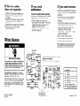
Now start...
n Carefullv place carton on its side.
Open bottom flaps. Set carton upright
with bottom flaps folded outward.
Remove carton from ice maker.
\
*
\\ A
Remove
n
interior packing.
L;
H Remove all tape and packing
material from outside and inside the ice
maker. Remove parts package from
inside the ice maker bin.
screw .
lower access panel
screws
3
n Remove the two screws in the
lower grille area and the one screw
from the center of the front panel
support. Pull forward and down to
remove the lower access panel.
4
n Turn the fan by hand to check
that it moves freely.
5
n Slightly loosen, Do Not remove,
the thumb screws holding the cutter grid
and water pan in place.
Slide ice maker onto cardboard/hard-
board before moving across the floor to
prevent damage to the floor covering.
6
n Move ice maker close to its final
position. Remove the cardboard/
hardboard from underneath ice maker.
Electrical Shock Hazard
Disconnect power supply at circuit
breaker or fuse box.
Failure to follow this instruction could
result in death or serious injury.
L
7
n Plug power supply cord into
grounded outlet.
8
n Insert the cold water supply
tubing through the hole in the rear of
the ice maker. Slide the ice maker into
final position. Center the ice maker in
the opening.
9
n Bend the cold water supply
tubing up toward the fitting. Attach the
water supply tubing to the cold water
inlet valve using the threaded
compression fitting. Check for good fit.
10
n Check that ice maker is
level from the front to back and side to
side. The ice maker must be level for
proper operation.
If necessary, shim the ice maker with
masonite or any hard, permanent
material so that it is level and held
tightly in place. If local codes require,
seal ice maker cabinet to floor with an
approved caulking compound.
11
n If the ice maker is installed
above 2,000 feet altitude, you must
adjust the bin and evaporator
thermostats. Remove the thermostats
and follow the directions on each
thermostat label for adjusting the
thermostats. Reinstall the thermostats,
Panel B


 1
1
 2
2
 3
3
 4
4
 5
5


KitchenAid KUIS185S User manual
KitchenAid KUIS155H User manual
Jenn-Air JIM1550ARW Owner's manual
Scotsman CS0415 User manual
U-Line CLR2060SSHR User manual
U-Line 2175WCOL User manual