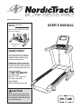
NordicTrack 24917.0 User manual
- Category
- Treadmills
- Type
- User manual
This manual is also suitable for

Serial Number
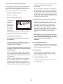
Decal
Model No. NTL19011.0
Serial No.
Write the serial number in the space
above for reference.
CAUTION
Read all precautions and instruc-
tions in this manual before using
this equipment. Save this manual
for future reference.
QUESTIONS?
If you have questions, or if parts
are damaged or missing, DO NOT
CONTACT THE STORE; please
contact Customer Care.
IMPORTANT: Please register this
product (see the limited warranty
on the back cover of this manual)
before contacting Customer Care.
CALL TOLL-FREE:
1-800-TO-BE-FIT
(1-800-862-3348)
Mon.–Fri. 6 a.m.–6 p.m. MT
Sat. 8 a.m.–4 p.m. MT
ON THE WEB:
www.nordictrackservice.com
www.nordictrack.com
USER’S MANUAL

2
WARNING DECAL PLACEMENT . . . . . . . . . . . . . . . . . . . . . . . . . . . . . . . . . . . . . . . . . . . . . . . . . . . . . . . . . . . . . . .2
IMPORTANT PRECAUTIONS ..................................................................3
BEFORE YOU BEGIN. . . . . . . . . . . . . . . . . . . . . . . . . . . . . . . . . . . . . . . . . . . . . . . . . . . . . . . . . . . . . . . . . . . . . . . .5
PART IDENTIFICATION CHART. . . . . . . . . . . . . . . . . . . . . . . . . . . . . . . . . . . . . . . . . . . . . . . . . . . . . . . . . . . . . . . .6
ASSEMBLY . . . . . . . . . . . . . . . . . . . . . . . . . . . . . . . . . . . . . . . . . . . . . . . . . . . . . . . . . . . . . . . . . . . . . . . . . . . . . . . .7
THE CHEST HEART RATE MONITOR. . . . . . . . . . . . . . . . . . . . . . . . . . . . . . . . . . . . . . . . . . . . . . . . . . . . . . . . . .14
OPERATION AND ADJUSTMENT .............................................................15
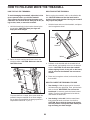
HOW TO FOLD AND MOVE THE TREADMILL . . . . . . . . . . . . . . . . . . . . . . . . . . . . . . . . . . . . . . . . . . . . . . . . . . .29
TROUBLESHOOTING ......................................................................30
EXERCISE GUIDELINES ....................................................................33
PART LIST. . . . . . . . . . . . . . . . . . . . . . . . . . . . . . . . . . . . . . . . . . . . . . . . . . . . . . . . . . . . . . . . . . . . . . . . . . . . . . . .34
EXPLODED DRAWING. . . . . . . . . . . . . . . . . . . . . . . . . . . . . . . . . . . . . . . . . . . . . . . . . . . . . . . . . . . . . . . . . . . . . .36
ORDERING REPLACEMENT PARTS. . . . . . . . . . . . . . . . . . . . . . . . . . . . . . . . . . . . . . . . . . . . . . . . . . . Back Cover
LIMITED WARRANTY. . . . . . . . . . . . . . . . . . . . . . . . . . . . . . . . . . . . . . . . . . . . . . . . . . . . . . . . . . . . . . . Back Cover
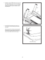
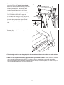
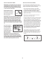
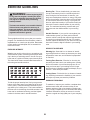
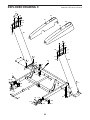
This drawing shows the locations of the warn-
ing decals. If a decal is missing or illegible,
call the telephone number on the front
cover of this manual and request a free
replacement decal. Apply the decal in the
location shown. Note: The decals may not
be shown at actual size.
WARNING DECAL PLACEMENT
256836
NORDICTRACK is a registered trademark of ICON IP, Inc.
TABLE OF CONTENTS

3
WARNING: To reduce the risk of serious injury, read all important precautions and
instructions in this manual and all warnings on your treadmill before using your treadmill. ICON
assumes no responsibility for personal injury or property damage sustained by or through the use of
this product.
IMPORTANT PRECAUTIONS
1. Before beginning any exercise program,
consult your physician. This is especially
important for persons over age 35 or persons
with pre-existing health problems.
2. It is the responsibility of the owner to ensure
that all users of this treadmill are adequately
informed of all warnings and precautions.
3. Use the treadmill only as described.
4. Keep the treadmill indoors, away from mois-
ture and dust. Do not put the treadmill in a
garage or covered patio, or near water.
5. Place the treadmill on a level surface, with
at least 8 ft. (2.4 m) of clearance behind it
and 2 ft. (0.6 m) on each side. Do not place
the treadmill on any surface that blocks air
openings. To protect the floor or carpet from
damage, place a mat under the treadmill.
6. Do not operate the treadmill where aerosol
products are used or where oxygen is being
administered.
7. Keep children under age 12 and pets away
from the treadmill at all times.
8. The treadmill should be used only by per-
sons weighing 375 lbs. (170 kg) or less.
9. Never allow more than one person on the
treadmill at a time.
10. Wear appropriate exercise clothes while
using the treadmill. Do not wear loose
clothes that could become caught in the
treadmill. Athletic support clothes are recom-
mended for both men and women. Always
wear athletic shoes. Never use the treadmill
with bare feet, wearing only stockings, or in
sandals.
11. Plug the power cord into a surge suppressor
(not included), and plug the surge suppres-
sor into an appropriate outlet (see page 15).
To avoid overloading the circuit, do not plug
other electrical devices, except for low-power
devices such as cell phone chargers, into
the surge suppressor or into an outlet on the
same circuit.
12. Use only a surge suppressor that meets all of
the specifications described on page 15. To
purchase a surge suppressor, see your local
NORDICTRACK dealer, call the telephone
number on the front cover of this manual, or
see your local electronics store.
13. Failure to use a properly functioning surge
suppressor could result in damage to the
control system of the treadmill. If the control
system is damaged, the walking belt may
slow, accelerate, or stop unexpectedly, which
may result in a fall and serious injury.
14. Keep the power cord and the surge suppres-
sor away from heated surfaces.
15. Never move the walking belt while the power
is turned off. Do not operate the treadmill
if the power cord or plug is damaged, or if
the treadmill is not working properly. (See
TROUBLESHOOTING on page 30 if the tread-
mill is not working properly.)
16. Read, understand, and test the emergency
stop procedure before using the treadmill
(see HOW TO TURN ON THE POWER on
page 17).
17. Never start the treadmill while you are stand-
ing on the walking belt. Always hold the
handrails while using the treadmill.
18. The treadmill is capable of high speeds.
Adjust the speed in small increments to
avoid sudden jumps in speed.

4
19. The heart rate monitor is not a medical
device. Various factors, including the user’s
movement, may affect the accuracy of heart
rate readings. The heart rate monitor is
intended only as an exercise aid in determin-
ing heart rate trends in general.
20. Do not attempt to raise, lower, or move the
treadmill until it is properly assembled. (See
ASSEMBLY on page 7, and HOW TO FOLD
AND MOVE THE TREADMILL on page 29.)
You must be able to safely lift 45 lbs. (20 kg)
to raise, lower, or move the treadmill.
21. When folding or moving the treadmill, make
sure that the storage latch is holding the
frame securely in the storage position.
22. Never insert any object into any opening on
the treadmill.
23. Inspect and properly tighten all parts of the
treadmill regularly.
24. DANGER: Always unplug the power
cord immediately after use, before cleaning the
treadmill, and before performing the mainte-
nance and adjustment procedures described
in this manual. Never remove the motor hood
unless instructed to do so by an authorized
service representative. Servicing other than
the procedures in this manual should be per-
formed by an authorized service representative
only.
25. This treadmill is intended for home use only.
Do not use this treadmill in a commercial,
rental, or institutional setting.
26. Over exercising may result in serious injury
or death. If you feel faint or if you experience
pain while exercising, stop immediately and
cool down.
SAVE THESE INSTRUCTIONS

5
Thank you for selecting the revolutionary
NORDICTRACK
®
ELITE 9500 PRO treadmill. The
ELITE 9500 PRO treadmill offers an impressive selec-
tion of features designed to make your workouts at
home more enjoyable and effective. And when you’re
not exercising, the unique treadmill can be folded up,
requiring less than half the floor space of other
treadmills.
For your benefit, read this manual carefully before
using the treadmill. If you have questions after
reading this manual, please see the front cover of this
manual. To help us assist you, please note the product
model number and serial number before contacting us.
The model number and the location of the serial num-
ber decal are shown on the front cover of this manual.
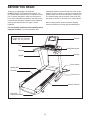
Before reading further, please review the drawing
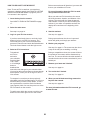
below and familiarize yourself with the labeled parts.
BEFORE YOU BEGIN
Handrail
Upright
Tray
Key/Clip
Power Switch
Walking Belt
Platform Cushion
Foot Rail
Power Cord
Idler Roller
Adjustment Screws
Console
Heart Rate Monitor
Length: 6 ft. 8 in. (203 cm)
Width: 3 ft. 2 in. (97 cm)

6
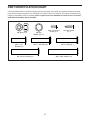
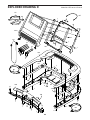
PART IDENTIFICATION CHART
Use the drawings below to identify small parts used for assembly. The number in parentheses below each draw-
ing is the key number of the part, from the PART LIST near the end of this manual. The number following the key
number is the quantity used for assembly. Note: If a part is not in the hardware kit, check to see if it is preat-
tached. Extra hardware may be included.
#8 x 3/4" Screw
(1)–4
3/8" Star
Washer (12)–14
3/8" Nut (11)–2
5/16" Star
Washer (10)–10
#10 x 3/4" Black
Screw (53)–4
3/8" x 2 3/4" Screw (7)–4
3/8" x 1 3/4" Bolt (6)–1
3/8" x 2" Bolt (3)–1
5/16" x 1"
Bolt (5)–4
#8 x 1/2" Ground
Screw (9)–1
3/8" x 1 1/4"
Screw (8)–4
1/4" x 1/2"
Bolt (36)–4
1/4" Star
Washer (35)–8
5/16" x 2" Bolt (4)–4
5/16" x 1 1/2"
Bolt (5)–4
3/8" x 2 1/2" Screw (4)–2
3/8" x 1"
Bolt (2)–4
5/16" x 1"
Bolt (2)–4

7
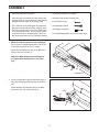
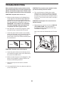
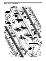
1. Make sure that the power cord is unplugged.
Place a piece of cardboard below the rear of the
Frame (56) to protect the floor or carpet.
Attach the Left Wheel Cap (96) to the Base (97)
with two #8 x 3/4" Screws (1).
Attach the Right Wheel Cap (not shown) to
the right side of the Base (97) in the same
way.
1
96
97
1
56
Cardboard
• Assembly requires two persons.
• Place all parts in a cleared area and remove the
packing materials. Do not dispose of the packing
materialsuntilyounishallassemblysteps.
• The underside of the walking belt is coated with
high-performance lubricant. After shipping, there
may be some lubricant on top of the walking belt
or on the shipping carton. This is normal. If there
is lubricant on top of the walking belt, wipe it off
with a soft cloth and a mild, non-abrasive cleaner.
• To identify small parts, see page 6.
• Assembly requires the following tools:
the included hex key
one adjustable wrench
one Phillips screwdriver
To avoid damaging parts, do not use power tools.
ASSEMBLY
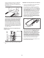
2. Pull the Upright Wire (84) and the Base Ground
Wire (94) through the indicated hole in the Base
(97).
Attach the Base Ground Wire (94) to the Base
(97) with a #8 x 1/2" Ground Screw (9).
84
2
Hole
9
94
97

8
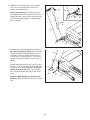
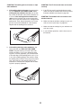
3. Identify the Left Upright (89), which is marked
“Left.” Have a second person hold the Left
Upright near the Base (97).
See the inset drawing. Tie the wire tie in the
Left Upright (89) securely around the end of the
Upright Wire (84). Then, pull the other end of the
wire tie until the Upright Wire is routed through
the Left Upright.
84
3
84
89
Wire
Tie
Wire
Tie
89
97
84
4. Hold the Left Upright (89) against the Base (97).
Be careful not to pinch the wires. If necessary,
position the Base Ground Wire (94) in the hole
in the side of the Left Upright. Insert two 3/8" x
2 3/4" Screws (7) and two 3/8" x 1 1/4" Screws
(8) with two 3/8" Star Washers (12) into the Left
Upright.
Partially tighten the 3/8" x 2 3/4" Screws (7) and
the 3/8" x 1 1/4" Screws (8) until the heads of the
Screws touch the Left Upright (89); do not fully
tighten the Screws yet. Note: It may be help-
ful to use the Short Hex Key (63) on the Screw
shown.
Attach the Right Upright (not shown) in the
same way. Note: There are no wires on the right
side.
89
97
63
4
8
7
12
94
12

9
6. Set the handrail assembly face down on a
soft surface to avoid scratching the handrail
assembly.
Remove two 3/8" x 2" Bolts (3) and a Handrail
Bracket (85) from each side of the handrail
assembly. The Handrail Brackets will be used in
step 7 and the Bolts will be used in step 9.
3
85
Handrail Assembly
6
5. Identify the Left and Right Base Covers (92, 93).
Slide the Left Base Cover onto the Left Upright
(89). Slide the Right Base Cover onto the Right
Upright (90). Do not press the Base Covers
into place yet.
89
93
90
5
92

10
8. With the help of a second person, hold the hand-
rail assembly near the Left Upright (89).
Connect the Upright Wire (84) to the Handrail
Wire (86). See the inset drawing. The connec-
tors should slide together easily and snap
into place. If they do not, turn one connector
and try again. IF YOU DO NOT CONNECT THE
CONNECTORS PROPERLY, THE CONSOLE
MAY BECOME DAMAGED WHEN YOU TURN
ON THE POWER. Then, remove the wire tie
from the Upright Wire.
Handrail
Assembly
Wire
Tie
86
89
84
84
86
8
7. Remove the four 3/8" x 1" Screws (2) from the
Uprights (89, 90).
Orient each Handrail Bracket (85) so that the
long tab is in the position shown and the large
holes are on top. Route the Upright Wire (84)
through the center hole in a Handrail Bracket.
Attach each Handrail Bracket (85) with the two
3/8" x 1" Screws (2) and two 3/8" Star Washers
(12). Start all four Screws, and then tighten
them.
2
12
85
84
2
Long
Tab
Large
Holes
12
85
Long
Tab
7
89
90

11
10. With the help of a second person, hold the con-
sole assembly near the handrail assembly. Be
careful not to pull on the wires during
assembly.
Connect the Handrail Wire (86) and then the
Pulse Wire (88) to the wires from the console.
The connectors should slide together eas-
ily and snap into place. If they do not, turn
one connector and try again. IF YOU DO NOT
CONNECT THE CONNECTORS PROPERLY,
THE CONSOLE MAY BECOME DAMAGED
WHEN YOU TURN ON THE POWER.
Set the metal bracket on the console assembly
onto the metal frame inside the handrail assem-
bly. Be careful not to pinch the wires.
Attach the console assembly with two 3/8" x
2 1/2" Screws (4) and two 3/8" Star Washers
(12). Start both Screws, and then tighten
them.
Console
Assembly
Console
Wire
Handrail
Assembly
10
86
88
Metal
Bracket
12
12
4
4
9. Insert the wires into the Left Upright (89) as you
set the handrail assembly on the Left and Right
Uprights (89, 90). Be careful not to pinch the
wires.
Attach the handrail assembly with the four 3/8" x
2" Bolts (3) that you removed in step 6 and four
3/8" Star Washers (12). Start all four Bolts, and
then tighten them.
9
Wires
12
3
12
89
90
3
Handrail
Assembly
Console
Wire

12
11. Firmly tighten the four 3/8" x 2 3/4" Screws
(7) first, and then tighten the four 3/8" x 1 1/4"
Screws (8) (only one side is shown).
Press the Left and Right Base Covers (92, 93)
onto the Base (97) until they snap into place.
11
93
8
92
97
7
13. Raise the Frame (56) to the position shown.
Have a second person hold the Frame until
this step is completed.
Orient the Storage Latch (53) so that the large
barrel and the latch knob are in the positions
shown.
Attach the lower end of the Storage Latch (53) to
the Base (97) with a 3/8" x 2" Bolt (3) and a 3/8"
Nut (11).
Attach the upper end of the Storage Latch (53)
to the Frame (56) with a 3/8" x 1 3/4" Bolt (6)
and a 3/8" Nut (11).
13
53
11
Large
Barrel
56
6
Latch
Knob
11
3
97
12. IMPORTANT: See page 15 and plug in the
power cord. Next, see page 17 and turn on
the power.
Then, press the 0 percent Incline button.
When the frame stops moving, remove the
key from the console and unplug the power
cord.
12
IMPORTANT:
Make sure to follow all
instructions in this step.

13
16. The adjustable cushions are shipped at their firmest settings. Adjust each cushion to a softer setting
before using the treadmill (see page 28).
17. Make sure that all parts are properly tightened before you use the treadmill. If there are sheets of plastic
on the treadmill decals, remove the plastic. To protect the floor or carpet, place a mat under the treadmill.
Note: Extra hardware may be included. Keep the included hex keys in a secure place; one of the hex keys is
used to adjust the walking belt (see pages 31 and 32).
14. Remove the packaging material from the bot-
tom of the Frame (56). See the inset drawing.
Make sure that the 1/2" Rear Leveling Foot Nuts
(30) are threaded all of the way onto the Rear
Leveling Feet (60). Then, turn the two Rear
Leveling Feet all of the way into the Frame.
Lower the Frame (56) (see HOW TO LOWER
THE TREADMILL FOR USE on page 29).
If one of the Rear Leveling Feet (60) doesn’t sit
flat on the floor, turn the Rear Leveling Foot until
it touches the floor, and then tighten the 1/2"
Rear Leveling Foot Nut (30) against the Frame
(56).
14
56
56
60
60
60
30
15. Press the Grommet (81) into the square hole in
the Base (97).
97
81
15

14
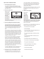
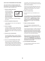
HOW TO PUT ON THE HEART RATE MONITOR
The heart rate
monitor consists of
a chest strap and a
sensor. Insert the
tab on one end of
the chest strap into
the hole in one end
of the sensor as
shown. Then, press
the end of the sen-
sor under the buckle
on the chest strap.
The tab should be
flush with the front of
the sensor.
The heart rate moni-
tor must be worn
under your clothes,
tight against your
skin. Wrap the heart
rate monitor around
your chest in the
location shown.
Make sure that
the logo is right-
side-up. Then, attach the other end of the chest strap
to the sensor. Adjust the length of the chest strap, if
necessary.
Pull the sensor away from your body a few inches and
locate the two electrode areas, which are covered by
shallow ridges. Using saline solution such as saliva or
contact lens solution, wet the electrode areas. Then,
return the sensor to a position against your chest.
CARE AND MAINTENANCE
• Thoroughlydrythesensorwithasofttowelafter
each use. Moisture may keep the sensor activated,
shortening the life of the battery.
•Storetheheartratemonitorinawarm,dryplace.
Do not store the heart rate monitor in a plastic bag or
other container that may trap moisture.
•Donotexposetheheartratemonitortodirect
sunlight for extended periods of time; do not expose
it to temperatures above 122° F (50° C) or below 14°
F (-10° C).
•Donotexcessivelybendorstretchthesensorwhen
using or storing the heart rate monitor.
•Tocleanthesensor,useadampclothandasmall
amount of mild soap. Then, wipe the sensor with a
damp cloth and thoroughly dry it with a soft towel.
Never use alcohol, abrasives, or chemicals to clean
the sensor. Hand wash and air dry the chest strap.
TROUBLESHOOTING
If the heart rate monitor does not function properly, try
the steps below.
• Makesurethatyouarewearingtheheartratemoni-
tor as described at the left. If the heart rate monitor
does not function when positioned as described,
move it slightly lower or higher on your chest.
• Ifheartratereadingsarenotdisplayeduntilyou
begin perspiring, rewet the electrode areas.
• Fortheconsoletodisplayheartratereadings,you
must be within arm’s length of the console.
• Ifthereisabatterycoveronthebackofthesensor,
replace the battery with a new battery of the same
type.
• Theheartratemonitorisdesignedtoworkwith
people who have normal heart rhythms. Heart rate
reading problems may be caused by medical
conditions such as premature ventricular contrac-
tions (pvcs), tachycardia bursts, and arrhythmia.
• Theoperationoftheheartratemonitorcanbe
affected by magnetic interference from high power
lines or other sources. If you suspect that magnetic
interference is causing a problem, try relocating the
fitness equipment.
THE CHEST HEART RATE MONITOR
Tab
Sensor
Buckle
Chest
Strap
Tabs
Sensor

15
OPERATION AND ADJUSTMENT
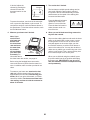
HOW TO CONNECT THE POWER CORD
Use a Surge Suppressor
Your treadmill, like other electronic equipment, can be
damaged by sudden voltage changes in your home’s
power. Voltage surges, spikes, and noise interfer-
ence can result from weather conditions or from other
appliances being turned on or off. To decrease the
risk of damaging the treadmill, always use a surge
suppressor with the treadmill. To purchase a surge
suppressor, see precaution 12 on page 3.
Use only a surge suppressor that is UL 1449 listed as a
transient voltage surge suppressor (TVSS). The surge
suppressor must have a UL suppressed voltage rating
of 400 volts or less and a minimum surge dissipation of
450 joules. The surge suppressor must also be electri-
cally rated for 120 volts AC and 15 amps. There must
be a monitoring light on the surge suppressor to indi-
cate whether it is functioning properly. Failure to use a
properly functioning surge suppressor could result
in damage to the control system of the treadmill
and serious injury to users.
Plug in the Power Cord
The treadmill must be grounded. If it should malfunc-
tion or break down, grounding provides a path of least
resistance for electric current to reduce the risk of elec-
tric shock. The treadmill power cord has a plug with a
grounding pin (see drawing 1 on this page).
Plug the power cord into a surge suppressor, and plug
the surge suppressor into an appropriate outlet that is
properly installed and grounded in accordance with all
local codes and ordinances. The outlet must be on a
nominal 120-volt circuit capable of carrying 15 or
more amps. To avoid overloading the circuit, do
not plug other electrical devices, except for low-
power devices such as cell phone chargers, into
the surge suppressor or into an outlet on the same
circuit. IMPORTANT: The treadmill is not compat-
ible with GFCI-equipped outlets and may not be
compatible with AFCI-equipped outlets.
A temporary
adapter may
be used to
connect the
surge sup-
pressor to
a 2-pole
receptacle
if a properly
grounded
outlet is not
available.
The lug or wire extending from the adapter must
be connected with a metal screw to a permanent
ground such as a properly grounded outlet box cover.
Some 2-pole receptacle outlet box covers are not
grounded. Before using an adapter, contact a quali-
fied electrician to determine whether the outlet box
cover is grounded. The temporary adapter should
be used only until a properly grounded outlet can
be installed by a qualified electrician.
DANGER: Improper connection
of the power cord increases the risk of elec-
tric shock. Do not modify the plug—if it will
not fit an outlet, have a proper outlet installed
by a qualified electrician. If you are unsure
whether the treadmill is properly grounded,
contact a qualified electrician.
1
Surge
Suppressor
Grounding Pin
Grounded Outlet
2
Adapter
2-pole Receptacle
Lug
Grounding Pin
Metal
Screw

16
ETS179410
(NTL17010, 24997)
CONSOLE DIAGRAM
FEATURES OF THE CONSOLE
The treadmill console offers an impressive array of
features designed to make your workouts more effec-
tive and enjoyable.
The console features revolutionary iFit Live technol-
ogy that enables the treadmill to communicate with
your wireless network. With iFit Live technology, you
can download personalized workouts, create your own
workouts, track your workout results, and access many
other features. See www.iFit.com for complete
information.
In addition, the console features a selection of onboard
workouts, including at least eight calorie workouts,
eight intensity workouts, eight speed workouts, eight
incline workouts, and six iFit Live demo workouts. Each
workout automatically controls the speed and incline of
the treadmill as it guides you through an effective exer-
cise session. In addition, you can set a calorie, time,
distance, or pace goal.
When you use the manual mode, you can change the
speed and incline of the treadmill with the touch of a
button.
As you exercise, the console will display instant exer-
cise feedback. You can also measure your heart rate
using the handgrip heart rate monitor or the chest heart
rate monitor.
You can even browse the Internet or listen to your
favorite workout music or audio books with the con-
sole’s stereo sound system while you exercise.
To turn on the power, see page 17. To learn how to
use the touch screen, see page 17. To set up the
console, see page 18.
Note: The console can display speed and distance in
either miles or kilometers. To find which unit of mea-
surement is selected, see step 4 on page 24. For
simplicity, all instructions in this section refer to miles.

17
HOW TO TURN ON THE POWER
IMPORTANT: If the treadmill has been exposed to
cold temperatures, allow it to warm to room tem-
perature before you turn on the power. If you do
not do this, you may damage the console display
or other electrical components.
Plug in the power cord (see
page 15). Next, locate the
power switch on the treadmill
frame near the power cord.
Make sure that the switch is
in the reset position.
IMPORTANT: The console features a display demo
mode, designed to be used if the treadmill is dis-
played in a store. If the demo mode is turned on,
the screen will show a preset presentation after
you plug in the power cord and press the power
switch into the reset position, before you insert the
key. To turn off the demo mode, see step 5 on page
24.
Next, stand on the foot
rails of the treadmill.
Locate the clip attached
to the key, and slide
the clip securely onto
the waistband of your
clothes. Then, insert the
key into the console.
Note: It may take a
minute for the console to be ready for use.
IMPORTANT: In an emergency, the key can be
pulled from the console, causing the walking belt
to slow to a stop. Test the clip by carefully taking
a few steps backward; if the key is not pulled from
the console, adjust the position of the clip.
HOW TO USE THE TOUCH SCREEN
The console features a tablet with a full-color touch
screen. The following information will help you become
familiar with the tablet’s advanced technology:
•Theconsolefunctionssimilarlytoothertablets.
You can slide or flick your finger against the screen
to move certain images on the screen, such as
the displays in a workout (see step 5 on page 19).
However, you cannot zoom in and out by sliding your
fingers on the screen.
•Thescreenisnotpressuresensitive.Youdonot
need to press hard on the screen.
•Totypeinformationintoatextbox,touchthetextbox
to view the keyboard. To use numbers or other char-
acters on the keyboard, touch the ?123 button. To
view more characters, touch the Alt button. Touch the
Alt button again to return to the number keyboard. To
return to the letter keyboard, touch the ABC button.
To use a capital character, touch the button with an
upward-facing arrow. To use multiple capital charac-
ters, touch the arrow button again. To return to the
lowercase keyboard, touch the arrow button a third
time. To clear the last character, touch the button
with a backward-facing arrow and an X.
•Usethebuttonsontheconsoleshowntonavigate
the tablet. Press the Back button to return to the
previous screen. Press the Home button to return to
the main menu. Note: The center button does not
function.
Reset
Back Home
ETS179410
(NTL17010, 24997)
Key
Clip

18
HOW TO SET UP THE CONSOLE
Before using the treadmill for the first time, set up the
console.
1. Connect to your wireless network.
Note: In order to access the Internet, download iFit
Live workouts, and use other features of the con-
sole, you must be connected to a wireless network.
See HOW TO USE THE WIRELESS NETWORK
MODE on page 26 to connect the console to your
wireless network.
2. Check for firmware updates.
First, see step 1 on page 24 and step 2 on page 25
and select the maintenance mode. Then, see step
3 on page 25 and check for firmware updates.
3. Calibrate the incline system.
See step 4 on page 25 and calibrate the incline
system of the treadmill (unless you already did so
during assembly).
4. Create an iFit Live account.
Touch the globe button near the lower-left corner of
the screen and touch the iFit Live button.
Note: For information about navigating in the
browser, see page 27. The browser will open to the
iFit.com home page. Touch the Register button in
the upper-right corner of the screen.
The browser will open to the iFit.com registration
page. Touch an entry box to view the keyboard.
Slide your finger up or down the screen to scroll up
or down the page.
Next, enter a username and password and your
e-mail address. Enter the activation code from the
iFit Live flier that came with the treadmill. Touch
the Place of Purchase drop-down menu for a list of
options; then, touch the location where you pur-
chased your product. Touch the words MEDICAL
DISCLAIMER, read the medical disclaimer,
touch the I Accept button, and check the medi-
cal disclaimer checkbox. Then, touch the Confirm
Activation Code button.
Enter the requested personal information. When
you have entered all of the information, touch the
Finish button. Then, touch the Home button on the
console to exit the browser.
The console is now ready for you to begin working out.
The following pages explain the various workouts and
other features that the console offers.
To use the manual mode, see page 19. To use an
onboard workout, see page 20. To use a set-a-goal
workout, see page 22. To use an iFit Live workout,
see page 23.
To use the equipment settings mode, see page 24.
To use the maintenance mode, see page 25. To use
the wireless network mode, see page 26. To use
the stereo sound system, see page 27. To use the
Internet browser, see page 27.
IMPORTANT: If there are sheets of plastic on the
console, remove the plastic. To prevent damage
to the walking platform, wear clean athletic shoes
while using the treadmill. The first time you use
the treadmill, observe the alignment of the walking
belt, and center the walking belt if necessary (see
page 32).

19
HOW TO USE THE MANUAL MODE
1. Insert the key into the console.
See HOW TO TURN ON THE POWER on page
17. Note: It may take a minute for the console to
be ready for use.
2. Select the main menu.
When you turn
on the power,
the main menu
should appear
after the
console boots
up. Touch the
home button in
the lower-left
corner of the screen (not shown here) to return to
the main menu at any time.
3. Start the walking belt and adjust the speed.
Touch the Start button on the screen or press the
Start button on the console to start the walking
belt. You can also press the Manual button on the
console, and then touch the Resume button on the
screen. The walking belt will begin to move at 1
mph.
As you exercise, change the speed of the walking
belt as desired by pressing the Speed increase and
decrease buttons. Each time you press one of the
buttons, the speed setting will change by 0.1 mph;
if you hold down the button, the speed setting will
change in increments of 0.5 mph.
If you press one of the numbered 1 Step Speed
buttons, the walking belt will gradually change
speed until it reaches the selected speed setting.
To select a speed setting that includes a decimal—
such as 3.5 mph—press two numbered buttons in
succession. For example, to select a speed setting
of 3.5 mph, press the 3 button and then immedi-
ately press the 5 button. Note: This will not function
if the console is set to metric units.
To stop the walking belt, press the Stop button. To
restart the walking belt, press the Start button.
4. Change the incline of the treadmill as desired.
To change the incline of the treadmill, press the
Incline/Decline increase and decrease buttons or
one of the numbered 1 Step Incline/Decline but-
tons. Each time you press one of the buttons, the
incline will gradually change until it reaches the
selected incline setting.
Note: The first time you adjust the incline, you must
first calibrate the incline system (see step 4 on
page 25).
5. Monitor your progress.
The console
offers sev-
eral display
modes. The
display mode
that you select
will determine
which workout
information is shown. To select the desired display
mode, simply flick or slide the screen. You can also
view additional information by touching the red
boxes on the screen.
As you walk or run on the treadmill, the screen can
show the following workout information:
•Theinclinelevelofthetreadmill
•Thetimeelapsed
• Thetimeleft(Note:Themanualmodedoesnot
have a time left countdown.)
•Theapproximatenumberofcaloriesyouhave
burned
• Theapproximatenumberofcaloriesyouare
burning per hour
• Thedistancethatyouhavewalkedorrun
• Thenumberofverticalfeetyouhaveclimbed
• Thespeedofthewalkingbelt
• Atrackrepresenting1/4mile(400m)
•Yourpaceinminutespermile
• Yourcurrentlapnumber
• Yourheartrate(seestep6)

20
If desired, adjust the
volume by pressing the
volume increase and
decrease buttons on the
console.
To pause the workout, touch one of the menu but-
tons or press the Stop button on the console. To
continue the workout, touch the Resume button or
the Start button. To end the workout session, touch
the End Workout button.
6. Measure your heart rate if desired.
Note: If you
use the hand-
grip heart rate
monitor and
the chest heart
rate monitor at
the same time,
the console
will not display
your heart rate
accurately. For
information about
the chest heart rate monitor, see page 14.
Before using the handgrip heart rate monitor,
remove the sheets of plastic from the metal con-
tacts. In addition, make sure that your hands are
clean.
To measure your heart rate, stand on the foot
rails and hold the contacts with your palms for
approximately ten seconds; avoid moving your
hands. When your pulse is detected, your heart
rate will be shown. For the most accurate heart
rate reading, continue to hold the contacts for
about 15 seconds.
7. Turn on the fan if desired.
The fan features multiple speed settings and an
auto mode. When the auto mode is selected,
the speed of the fan will automatically increase
and decrease as the speed of the walking belt
increases and decreases.
Press the Manual fan button
repeatedly to select a fan
speed or to turn off the fan.
Press the Auto fan button to
select the auto mode or to
turn off the fan.
8. When you are finished exercising, remove the
key from the console.
Step onto the walking platform and touch the home
button or the back button on the screen or press
the Stop button on the console. A workout sum-
mary will appear on the screen. After you view
the workout summary, touch the Finish button to
return to the main menu. You may also be able to
either save or publish your results using one of the
options on the screen. Then, remove the key from
the console and put it in a secure place.
When you are finished using the treadmill, press
the power switch into the off position and unplug
the power cord. IMPORTANT: If you do not do
this, the treadmill’s electrical components may
wear prematurely.
Contacts
Increase
Decrease
Page is loading ...
Page is loading ...
Page is loading ...
Page is loading ...
Page is loading ...
Page is loading ...
Page is loading ...
Page is loading ...
Page is loading ...
Page is loading ...
Page is loading ...
Page is loading ...
Page is loading ...
Page is loading ...
Page is loading ...
Page is loading ...
Page is loading ...
Page is loading ...
Page is loading ...
Page is loading ...
-
 1
1
-
 2
2
-
 3
3
-
 4
4
-
 5
5
-
 6
6
-
 7
7
-
 8
8
-
 9
9
-
 10
10
-
 11
11
-
 12
12
-
 13
13
-
 14
14
-
 15
15
-
 16
16
-
 17
17
-
 18
18
-
 19
19
-
 20
20
-
 21
21
-
 22
22
-
 23
23
-
 24
24
-
 25
25
-
 26
26
-
 27
27
-
 28
28
-
 29
29
-
 30
30
-
 31
31
-
 32
32
-
 33
33
-
 34
34
-
 35
35
-
 36
36
-
 37
37
-
 38
38
-
 39
39
-
 40
40


NordicTrack 24917.0 User manual
- Category
- Treadmills
- Type
- User manual
- This manual is also suitable for
Ask a question and I''ll find the answer in the document
Finding information in a document is now easier with AI
Related papers
-
NordicTrack C1750PRO 24924.0 User manual
-
-
-
FreeMotion t5.8c User manual
-
-
-
-
-
-
Other documents
-
Pro-Form Power 1080i User manual
-
-
-
ProForm Power 1080i User manual
-
-
-
Epic Tl 2710 Treadmill User manual
-
-
-