Honeywell CT2800 Owner's manual

Category
Thermostats
Type
Owner's manual

Honeywell CT2800 is a programmable thermostat designed to provide automatic temperature control and energy savings. It's compatible with conventional, electric baseboard, steam, heat pump, and multistage heating/cooling systems. The CT2800 features a 5-day/2-day programmable schedule, allowing you to set different temperatures for weekdays and weekends. It also includes a large, easy-to-read display, battery-powered operation, and a temporary override function for quick adjustments.

Honeywell CT2800 is a programmable thermostat designed to provide automatic temperature control and energy savings. It's compatible with conventional, electric baseboard, steam, heat pump, and multistage heating/cooling systems. The CT2800 features a 5-day/2-day programmable schedule, allowing you to set different temperatures for weekdays and weekends. It also includes a large, easy-to-read display, battery-powered operation, and a temporary override function for quick adjustments.

69-1638-1
INSTALLATION AND PROGRAMMING INSTRUCTIONS
® U.S. Registered Trademark
Copyright © 2003 Honeywell International Inc.
All Rights Reserved
CT2800 Programmable Thermostat
Welcome to the world of comfort and energy savings with your
new Honeywell Programmable Thermostat. Your new thermostat
will automatically control the temperature in your home, keeping
you comfortable while saving energy.
Weekday/Weekend (5-day/2-day)
Programmable Heat and/or Cool
Low Voltage (20 to 30 Vac)
Thermostat and Mounting Plate
Model CT2800
Table of Contents
Installation .................................................................................................................................................................. 2
Programming.............................................................................................................................................................. 12
Operation.................................................................................................................................................................... 18
Frequently Asked Questions ...................................................................................................................................... 22
Customer Assistance ................................................................................................................................................. 23
Limited Warranty ........................................................................................................................................................ 24
69-1638—1 2
MERCURY NOTICE
If you are removing an old thermostat that contains mercury in a sealed tube
(Fig. 1), do not place the old thermostat in the trash. Contact your local waste
management authority for instructions regarding recycling and the proper
disposal of the old thermostat.
Installation
INSTALLATION
Verify You Have Correct Thermostat
Make sure that the CT2800 is the correct thermostat for your heating/cooling system. Read the compatibility chart
below to determine which system you have. If your system is not compatible with the CT2800, the table recommends
an alternate Honeywell model. If you are unsure what type of thermostat is right for your system, visit us on the Web at
www.honeywell.com/yourhome or call Honeywell Customer Care at 1-800-468-1502.
Heating/Cooling System
Compatible
with CT2800? Alternate Model
Conventional
Single stage systems that include warm air furnaces and hot water.
Yes
Electric Baseboard
Electric-powered heating strips located just above the floor, usually 120 to 240
volts.
No CT1950 for 240
volts
M3701
MERCUR
Y
SWITCH
Fig. 1.
3 69-1638—1
Step 1. Prepare for Installation
1. Carefully unpack your new thermostat. Save your receipt and make sure you have the following parts:
Thermostat and mounting plate
Labels
Screws and anchors
Installation and Programming Instructions
2. Gather the needed tools and supplies listed below.
3. Make sure that your heating and cooling systems are working properly. If there is a problem with either system,
call a heating/air conditioning contractor—the problem may persist after you install the new thermostat.
IMPORTANT:
To avoid damaging the compressor in the air conditioner, do not operate the cooling system when the tem-
perature outdoors is below 50°F (10°C).
Steam
A steam boiler with radiator heat.
No CT3600
Heat Pump
Heating and cooling are produced from the same outdoor unit (compressor) with
no auxiliary or backup heat.
No CT3600
Multistage Heat Pump
Heating and cooling are produced from the same outdoor unit (compressor) with
auxiliary or backup heat.
No CT3611
Multistage Conventional
A heating or cooling system with more than one stage.
No See your
contractor
Required Tools and Supplies Optional Tools
Two AA alkaline batteries. Honeywell recommends Energizer®
batteries.
Screwdriver.
Hand or power drill with 3/16-inch or 7/32-inch drill bit.
Pencil.
Wire cutter/stripper or sharp knife.
Level.
Electrical tape.
Heating/Cooling System
Compatible
with CT2800? Alternate Model
69-1638—1 4
Step 2. Remove Old Thermostat
Fig. 2. a. Turn off power to the heating/cooling system, either at the furnace or
at the fuse/circuit breaker panel.
b. Remove the cover of your old thermostat (Fig. 2).
c. Unscrew and remove the old thermostat’s mounting plate from the
wall, but do not disconnect the wires.
d. Inspect old thermostat wiring. If wiring meets any of the following
conditions, see special wiring instructions section after Step 7.
Fig. 3. The old thermostat is a clock thermostat with wires attached to
the C or C1 terminals.
The old thermostat has six or more wires, excluding wires
attached to C or C1 terminals.
The old thermostat has three wires.
There are five wires connected to the old thermostat.
There are extra wires that are not connected to the old
thermostat.
e. Using enclosed labels, mark wires with letter of terminal it is attached
to on the old thermostat (Fig. 3). Do not label using colors. If labels
do not match letters on old thermostat terminals, see wiring cross ref-
erence table in Special Wiring Instructions section.
Fig. 4. f. Disconnect the wires from the old thermostat and wrap the wires
around a pencil to keep them from falling back into the wall.
NOTE: Remember, if your old thermostat contains mercury, you
must recycle it. See Mercury Notice for more recycling
information.
Check your progress
Your wall should now look like Fig. 4.
M2014
0
M19086
WIRES THROUG
H
WALL OPENING
M20133
5 69-1638—1
Step 3. Install Mounting Plate
Fig. 5. a. Separate the mounting plate from the thermostat using a coin, as
shown in Fig 5.
b. Position the mounting plate on the wall. Be sure the mounting plate is
flush against the wall and none of the wires are trapped behind it.
c. Level the mounting plate and use a pencil to mark the center of the
mounting plate screw holes.
d. Remove the mounting plate and drill holes at the locations marked.
For drywall, drill two 3/16-inch holes.
For plaster or wood, drill two 7/32-inch holes.
Fig. 6. e. If installing in drywall, gently tap the anchors (provided) into the drilled
holes until they are flush with the wall.
f. Reposition the mounting plate over the holes, pull the wires through
the wiring opening, and loosely insert the mounting screws into each
of the drilled holes or anchors (Fig. 6).
g. Make sure the mounting plate is level and tighten the mounting
screws.
Fig. 7.
Check your progress
The mounting plate is now mounted on the wall and should look like
Fig. 7.
M20139
M20129
M2012
8
W
R
G
R
c
Y
69-1638—1 6
Step 4. Set Thermostat for Your Type of Heating System
IMPORTANT:
Setting your thermostat cor-
rectly for your type of heating
system allows it to maintain
accurate temperature control,
minimize swings in the tem-
perature of the room, and
efficiently run the fan.
a. Use the FUEL SWITCH
on the back of the thermostat
to set your new thermostat
for the type of fuel that your
heating system uses: F–
gas or oil, or E–electric.
NOTE: This setting enables
proper fan operation.
b. Use DIP switches 1 and 2
on the back of the thermostat
to set your new thermostat
for your type of heating sys-
tem. See the Heating System
Table on the next page to find
the correct settings.
NOTE: These DIP switches
are factory-set for a warm air,
gas, or oil heating system.
c. The thermostat is set to display the temperature in degrees Fahrenheit (°F). If you want to display the temperature
in degrees Celsius (°C), turn DIP Switch 3 to Off position.
d. You can install the batteries and program your thermostat now, or you can wait until the thermostat is mounted on
the wall. To install the batteries, see Step 7. To program the thermostat, see the Programming section.
Fig. 8.
M20637
R
W Y G
W Y G
C R R
THERMOSTAT BACK
DISPLAY F
DISPLAY C
3 - ON
3 - OFF
F
E
FUEL SWITCH
WARM AIR
FURNACE
1 - ON 2 - ON F
1 - OFF 2 - ON F
1 - ON 2 - OFF E
FUEL SWITCH
POSITION
DIP SWITCH
POSITION
HEATING
SYSTEM
C
C
C
1
OFF ON
2
3
ON
1
2
3
HOT WATER OR
HIGH EFFICIENCY
ELECTRIC
FURNACE
7 69-1638—1
Heating System Table
Step 5. Wire Thermostat Terminals
Type of System
D I P S w i t c h e s
1 and 2 Fuel Switch
Warm air, gas, or oil heating system with an efficiency rating under 90%.
(The furnace efficiency rating should be on the furnace.)
Use factory setting
1–On; 2–On
F
High-efficiency furnace such as a 90% or greater AFUE (Average Fuel
Utilization Efficiency) unit
1–Off; 2–On F
Hot water boiler 1–Off; 2–On F
Electric furnace 1–On; 2–Off E
Fig. 9. a. Hold thermostat as shown in Fig. 9.
b. Using the labels on the wires, match letter of your old thermostat wire
with the corresponding terminal on the back of your new thermostat.
NOTE: If letters on old thermostat terminals do not match letters on
new thermostat terminals, all old wires may not need connect-
ing to new thermostat. See Special Wiring Instructions section.
Fig. 10. c. Loosen terminal screws and slip each wire beneath its matching
terminal (Fig 10).
d. Securely tighten terminals.
W
Y
G
R
M2012
5
INSERT
STRAIGHT
UNDER
SCREW HEAD
5
/16 in.
(
8 mm)
S
TRIP
END OF WIR
E
VISIBLE HER
E
M20126
69-1638—1 8
Step 6. Mount Thermostat
Fig. 11. Fig. 12. e. Align the tabs at the top of the thermostat with the
tabs at the top of the mounting plate (Fig. 11).
f. Press the lower edge of the case to latch the
bottom of the thermostat (Fig. 12)
M2013
0
M2013
1
9 69-1638—1
Step 7. Install the batteries
Special Wiring Instructions
Clock thermostat with C or C1 terminals
A clock thermostat has one or two extra wires attached to the C or C1 terminals that allow the clock to operate. These
wires are not used during the installation of your new CT2800 Thermostat and must be insulated from each other to
avoid damaging your electrical circuit.
a. Make sure that power to the heating/cooling system is turned off.
b. Locate the wires that are connected to the clock terminals marked C or C1.
c. As you disconnect the wires, do not allow these wires to touch.
d. Wrap the wires separately, using electrical tape to insulate the wires.
e. Place the wires where they do not interfere with the operation of the new thermostat.
You will not connect these wires to your CT2800 Thermostat.
f. Continue with the installation.
Fig. 13.
Fig. 14.
IMPORTANT:
Batteries must be installed for programming and operation of
the thermostat and heating/cooling system. Honeywell recom-
mends using Energizer® batteries.
a. Make sure that the System switch is set in the OFF position.
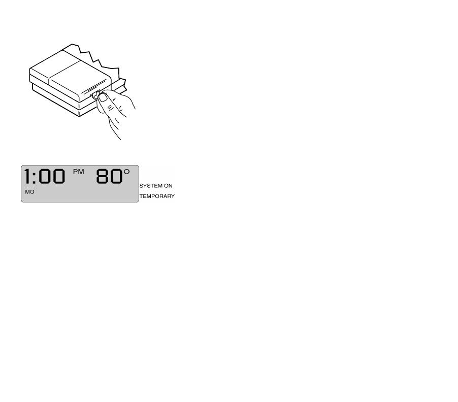
b. Using a coin, open the battery door as shown in Fig. 13.
c. Install the batteries. Make sure that the positive and negative termi-
nals are oriented correctly as marked inside the battery case.
d. Replace the battery door.
e. Remove the clear plastic label from the digital display.
Check your progress
When the batteries are installed correctly, the digital display flashes all
entries once, then begins to flash a default time and the current
temperature (Fig. 14). The flashing continues until you begin to program
the thermostat. You are now ready to program the thermostat. See
Programming section.
M1719C
REMOVING
BATTERY
DOOR
69-1638—1 10
Six or more wires
If your old thermostat has six or more wires (excluding clock wires attached to the C or C1 terminals), your heating/
cooling system is most likely a variation of a heat pump or multistage system. Your CT2800 Thermostat will NOT work
with such systems and should be returned to the place of purchase. See the thermostat compatibility table for
information about which programmable thermostat will work with your system.
Three thermostat wires
If you have three wires for heating only and can operate the fan using the fan ON switch, the CT2800 Thermostat will
work with your system. Continue the installation procedure.
If you have a three-wire heating-only system and cannot operate the fan using the fan ON switch, the CT2800
Thermostat will probably NOT work with your system. Contact your heating contractor for installation assistance.
Wires that are not connected to old thermostat
If there are extra wires that do not connect to your old thermostat, do not label them. You will not connect these wires
to your new thermostat. Tape off the wires individually with electrical tape and place them where they will not interfere
with the operation of the new thermostat. Continue the installation procedure.
Five wires connected to old thermostat
Your new thermostat has a factory-installed metal jumper between the R and Rc
terminals (Fig. 15). Remove the jumper before wiring the R and Rc terminals.
Thermostat C Terminal
This thermostat does not use the C wiring terminal.
M20127
JUMPER (FACTORY-
INSTALLED). REMOVE
IF 5-WIRE SYSTEM
R
R
WY G
Fig. 15.
11 69-1638—1
Old thermostat terminals that do not match new thermostat terminals
Use the table below to wire the new thermostat.
*Remove factory-installed jumper between R and Rc terminals in 5-wire systems.
Old Thermostat
Terminal
Connect to New
Thermostat
Terminal Description
R, RH, 4, V R* Power
Rc, R Rc* Power for cooling
W, W
1
, H W Heat
Y, Y
1
, M Y Cooling
G, F G Fa n
O Do not continue
installation
Changeover in cool (O terminal) or changeover in heat (B terminal).
You have a single-stage heat pump or zoning system. Select an alternate
thermostat model.
B
C, X, B Do not connect Transformer common.
W
2
, H
2
Do not continue
installation.
Second stage heat (W
2
, H
2
) or second stage cooling (Y
2
).
You have a multistage heating/cooling system. Select an alternate
thermostat model.
Y
2
69-1638—1 12
PROGRAMMING
Faceplate Illustration and Description
Descriptions
Fig. 16. 1 Fan switch–Selects automatic fan
operation or fan on.
2 Set Schedule–Puts the thermostat into
programming mode.
3 Set Clock/Day–Sets the clock and day.
4 Time Ahead and Back–Sets the time
ahead and back.
5 Program periods–Current program period
or period being programmed.
6 Day of the week–Current day or day being
programmed.
7 Time–Current time or program time.
8 Temperature–Room temperature or
programmed temperature.
9 SYSTEM ON–An arrow displays when the
heating/cooling system is running.
10 TEMPORARY–An arrow displays when a
temporary override is made to the
program.
11 Temp Warmer and Cooler–Sets the
temperature warmer and cooler.
12 Run Program–Returns thermostat to
normal operating mode
13 Hold Temp–Holds a selected temperature.
14 System switch–Selects Cool, Off, Heat.
Fan
Auto On
System
Cool Off Heat
SYSTEM ON
TEMPORARY
Temp
AM
PM
MO TU WE TH FR SA SU
WAKE LEAVE RETURN SLEEP
SET
M20664
1
2
3
4
5
6
14
13
12
11
10
9
7 8
Run
Program
Hold
Temp
Clock/Day
Schedule
Set Time Mode
13 69-1638—1
Step 1. Set Current Time and Day
Step 2. Learn About Programming Features
Your CT2800 Thermostat allows you to program schedules for both a heating season and a cooling season.
During the heating season, you will want to set the normal room temperature higher and the energy-saving
temperature lower.
The reverse is true during the cooling season—the normal room temperature will be lower and the energy-saving
temperature higher.
For each season, you can set up to four program periods for the weekdays (Monday–Friday), and up to two program
periods for the weekends (Saturday and Sunday). The program periods are defined in the following table.
a. Press once.
The time is displayed (Fig. 17).
b. Press Time until the current time is displayed.
Fig. 17.
c. Press again.
The day is displayed (Fig. 18).
d. Press Time
until the current day is displayed.
Fig. 18.
e. Press once.
The current time and day and the current temperature are
displayed (Fig. 19).
Fig. 19.
Clock/Day
Clock/Day
Run
Program
69-1638—1 14
Programming Tips
You do not need to program times and temperatures for all program periods.
If you decide not to program your thermostat, it automatically controls heating at 68°F (20°C), and cooling at 78°F
(26°C), 24 hours a day.
If you decide not to program weekend schedules, the temperature that is programmed for the weekday SLEEP
schedule remains in effect until the next program period, which begins on Monday morning.
The temperatures cannot be set any higher than 88°F (31°C) or any lower than 45°F (7°C).
When pressing the buttons, use the ball of your finger or a soft pencil eraser. Using sharp fingernails or pencil
points can damage the keypad.
If you make an error at any time during programming, press . Then press until you reach the
program period you last programmed.
Program Period Description When Available
WAKE
The time when you get up and get ready to leave your home. You can
set the system at a comfortable temperature for this period.
Weekdays and weekend
LEAVE
The time when you are regularly away from home. You can set up an
energy-saving temperature for this period.
Weekdays only
RETURN
The time between returning home and going to bed. You can set the
system at a comfortable temperature for this period.
Weekdays only
SLEEP
The time when you are sleeping. You can set up an energy-saving
temperature for this period.
Weekdays and weekend
Run
Program
Schedule
15 69-1638—1
Step 3. Program Heating Schedule
a. Write in the times and temperatures that you want to program for your heating schedule.
Heating Schedule
Program
Period WAKE LEAVE RETURN SLEEP
Suggested
Settings
Time
6:00 AM 8:00 AM 6:00 PM 10:00 PM
Temp 70°F (21°C) 62°F (16.5°C) 70°F (21°C) 62°F (16.5°C)
Weekday (Mon–Fri) Time
Tem p
Weekend (Sat–Sun) Time
Tem p
b. Set the System switch to HEAT.
c. Press once.
A blank schedule is displayed (Fig. 20).
Fig. 20.
d. Set the Monday–Friday WAKE time by pressing
Time
until the desired time is displayed (Fig. 21).
e. Set the Monday–Friday WAKE temperature by pressing
Temp until desired temperature is displayed.
Fig. 21.
Schedule
69-1638—1 16
f. Press to display a blank schedule for the next pro-
gram period (Fig. 22) and repeat steps d. through f. for each
weekday program period.
Fig. 22.
g. Press until the weekend schedule is displayed (Fig.
23).
h. Set the Saturday and Sunday WAKE time by pressing
Time until the desired time is displayed.
Fig. 23.
i. Set the Saturday and Sunday WAKE temperature by
pressing Temp until desired temperature displays
(Fig. 24).
j. Press again to display blank schedule for SLEEP
program period and repeat steps h. through j. to set pro-
gram.
k. Press to start the program.
Fig. 24.
Schedule
Schedule
Schedule
Run
Program
17 69-1638—1
Step 4. Program Cooling Schedule
a. Write in the times and temperatures you want to program for your cooling schedule.
b. Set the System switch to COOL.
c. Repeat steps 3c. through 3k. to program the weekday and weekend cooling schedule.
Step 5. Check System
Verify that your heating system works
Verify that your cooling system works
IMPORTANT:
To avoid damaging the compressor in the air conditioner, do not operate the cooling system when the tem-
perature outdoors is below 50°F (10°C).
Cooling Schedule
Program
Period WAKE LEAVE RETURN SLEEP
Suggested
Settings
Time
6:00 AM 8:00 AM 6:00 PM 10:00 PM
Temp 78°F (25.5°C) 85°F (29.5°C) 78°F (25.5°C) 82°F (28°C)
Weekday (Mon–Fri) Time
Tem p
Weekend (Sat–Sun) Time
Tem p
a. Set the System switch to Heat, and the Fan switch to Auto.
b. Press Temp until the setting is 10°F (6°C) above
room temperature (Fig. 25). Your heating system should start
and the fan should run after a short delay.
Fig. 25.
c. Press Temp until the setting is 10°F (6°C) below
room temperature. Your heating system should shut off.
69-1638—1 18
OPERATION
Change Clock for Daylight/Standard Time
a. Press once. The time is displayed.
b. Press and hold Time until the correct time is displayed.
c. Press once. The current time and day and current temperature display.
d. Set the System switch to Cool, and the Fan switch to Auto.
e. Press Temp until the setting is 10°F (6°C) below
room temperature (Fig. 26). Your cooling system and fan
should start.
NOTE: When cooling setting is changed, thermostat
can delay up to five minutes before turning on
air conditioner. This delay protects the compres-
sor.
Fig. 26.
f. Press Temp until setting is 10°F (6°C) above room
temperature.Your cooling system and fan should stop.
g. Set the System switch to Off and the Fan switch to Auto.
The cooling system and fan should be off.
Clock/Day
Run
Program
19 69-1638—1
Set Fan and System Switches
The switches on the bottom of the thermostat faceplate control the operation of your fan and the heating and cooling
system. Set the Fan switch first and then set the System switch.
Replace Batteries
As the batteries run low, your thermostat shows the following in the digital display:
a. Make sure that the System switch is set to the OFF position.
b. Open the battery door.
c. Press on the left side of the batteries to remove them.
NOTE: If new batteries are inserted within 20-30 seconds of removing old ones, reprogramming is not
needed. If display is blank, batteries are dead or incorrectly installed and reprogramming is needed.
Switch Setting Result
Fan Auto A single-speed fan turns on automatically with the air conditioner or furnace.
A two-speed fan usually runs on high with the air conditioner and on low with the furnace.
Auto is the normal setting for most homes.
On The fan runs continuously. Use this setting for improved air circulation during special
occasions or for more efficient air cleaning.
NOTE: In a heat-only system, the fan runs continuously only if the fan wire has been con-
nected to the G terminal on the back of the thermostat.
System Cool The thermostat controls your air conditioning system.
Off Both the heating and air conditioning systems are off.
Heat The thermostat controls your heating system.
If you see: Batteries are: You should:
Flashing “bAt Lo” Low Replace the batteries as soon as possible, within the month.
Blank display Dead Replace the batteries immediately. Your heating/cooling system is not
operating.
69-1638—1 20
d. Install new batteries. Make sure that positive and negative terminals are oriented as marked inside battery case.
e. Close the battery door and set the System switch to HEAT or COOL.
NOTE: If “bAt Lo” continues to display after replacing the batteries, set System switch to OFF, insert batteries back-
ward, wait for five to ten seconds, and return batteries to correct orientation. Then reprogram.
IMPORTANT:
Replace batteries once a year to prevent heating/cooling system from shutting down due to lack of battery
power in thermostat. If leaving home for longer than a month, change batteries before leaving.
Override program settings
NOTE: Make sure the System switch is set to either HEAT or COOL before making any changes to the schedule.
Change the temperature temporarily
Press or until the desired temperature is displayed.
An arrow is displayed, indicating that the change is temporary
(Fig. 27).
NOTE: A temporary change to temperature lasts for current
program period only. Heating/cooling schedule you
programmed resumes when next scheduled program
period is reached.To cancel temporary change before
next scheduled program period, press .
Fig. 27.
Run
Program
  • Page 1 1
  • Page 2 2
  • Page 3 3
  • Page 4 4
  • Page 5 5
  • Page 6 6
  • Page 7 7
  • Page 8 8
  • Page 9 9
  • Page 10 10
  • Page 11 11
  • Page 12 12
  • Page 13 13
  • Page 14 14
  • Page 15 15
  • Page 16 16
  • Page 17 17
  • Page 18 18
  • Page 19 19
  • Page 20 20
  • Page 21 21
  • Page 22 22
  • Page 23 23
  • Page 24 24

Honeywell CT2800 Owner's manual

Category
Thermostats
Type
Owner's manual

Honeywell CT2800 is a programmable thermostat designed to provide automatic temperature control and energy savings. It's compatible with conventional, electric baseboard, steam, heat pump, and multistage heating/cooling systems. The CT2800 features a 5-day/2-day programmable schedule, allowing you to set different temperatures for weekdays and weekends. It also includes a large, easy-to-read display, battery-powered operation, and a temporary override function for quick adjustments.

Ask a question and I''ll find the answer in the document

Finding information in a document is now easier with AI