Page is loading ...

Motoriduttore per basculanti
Gear-motor for overhead doors
Motoreducteur pour portes basculantes
Getriebe für schwinggitter
Motorreductores para portones basculantes
Motorredutores para portões basculantes
2006
MANUALE ISTRUZIONI
INSTRUCTION MANUAL
LIVRET D’INSTRUCTIONS
ANLEITUNGS HEFT
MANUAL DE INSTRUCCIONES
MANUAL DE INSTRUÇÕES
I
GB
F
D
E
P
I
GB
F
D
E
P
900BS-50N
900BS-50CL
900BS-50C
900BS-50-24
MADE IN ECC
REV 01_2007

INDICE
3
MODELLI E CARATTERISTICHE
DATI TECNICI
QUADRO D’INSIEME
VERIFICHE PRELIMINARI
MANUTENZIONE
SMALTIMENTO
RACCOMANDAZIONI FINALI
INDICE
4
5
2
2
QUESTO LIBRETTO E’ DESTINATO SOLO ALL’INSTALLATORE
L’installazione dovrà essere effettuata solamente da personale
professionalmente qualificato in conformità a quanto previsto dalla legge
vigente.
ELENCO PEZZI DI RICAMBIO
I
DIMENSIONI D’INGOMBRO
FUNZIONAMENTO MANUALE
INSTALLAZIONE
6-7
8
9-10
DICHIARAZIONE DI CONFORMITA’
Il sottoscritto Romeo Bissoli, Amministratore Delegato della ditta
KEY AUTOMATION S.r.l. Via L. Da Vinci, 12 31010 Godega S. Urbano (TV) ITALIA
dichiara che il prodotto
Key Automation S.r.l. Via L. Da Vinci, 12 31010 Godega di S. Urbano (TV) ITALIA
dichiara che il prodotto
Ricevitore radio /
Tipo/
Risulta conforme a quanto previsto dalle seguenti direttive comunitarie:
:
-Direttiva/ 73/23/CEE modificata dalle Direttive 93/68/CEE, come recepita dal
D.L. 18 ottobre 1977 n° 791
-Direttiva/ 89/336/CEE modificata dalle Direttive 92/31/CEE,93/68/CEE e 93/97/CEE
come recepita dal D.L. 12 novembre 1996 n°615
Risulta conforme a quanto previsto dalle seguenti Norme armonizzate:
:
EN60335-1:1994 + A11:95 + A1:96 + A12:96
EN50081-1:1992
EN50082-2:1995
EN55014-1:1993 + A1:1997 + A2:1999
Inoltre dichiara che non è consentita la messa in servizio prima che la macchina
in cui il prodotto stesso è incorporato non sia dichiarata conforme alla direttiva
macchine 98/37/CEE.
Godega di S.U., 10/09/04
Amministratore Delegato
()
Romeo Bissoli
The undersigned Romeo Bissoli General Manager of the firm
declares that the product
declares that the product
Receiver
Type
Appears to be in conformity with the following community (EEC) regulations
Directive
modified by the directive 73/23/CEE like recepied from
the Law of 18 October 1977 n. 791
Directive
modified by the directive 92/31/CEE,93/68/CEE and 93/97/CEE
like recepied from the Law of 12 November 1996 n°615
Appears to be in conformity with the following harmonized standards regulations
He declares, moreover, that is not allowed to use the above mentioned product until the
machine, in which this product is incorporated, has been identified and declared in
conformity with the regulation 98/37/CE.
General Manager
BS-50CL
BS-50C
BS-50N

6
12
6
3
6
10
MODELLI E CARATTERISTICHE
DATI TECNICI
-
230VAC
340W
1,5 A
12,5
IP 43
0,76 M/S
9MQ
I
30%
-20°/+70°
14 KG
µF
CT-24
24VDC
150W
6A
-
IP 43
0,80 M/S
9MQ
I
80%
-20°/+70°
13,8 KG
CT 1A
230VAC
340W
1,4 A
12,5
IP 43
0,76 M/S
9MQ
I
30%
-20°/+70°
14 KG
µF
CT 1E
230VAC
340W
1,5 A
12,5
IP 43
0,76 M/S
9MQ
I
30%
-20°/+70°
14 KG
µF
CENTRALINA
ALIMENTAZIONE
POTENZA ASSORBITA
ASSORBIMENTO MOTORE
CONDENSATORE
GRADO DI PROTEZIONE
VELOCITA’
DIMENSIONI MAX PORTONE
CLASSE DI ISOLAMENTO
SERVIZIO TEMPORANEO
TEMPERATURA DI ESERCIZIO
PESO
900BS-50N
900BS-50CL
900BS-50-24
900BS-50C
Motoriduttore elettromeccanico irreversibile, 230 Vac per portoni basculanti a molle
o a contrappesi di dimensioni fino a 9mq, con finecorsa in apertura e chiusura già
montate
Motoriduttore elettromeccanico irreversibile, 24Vdc per portoni basculanti a molle
o a contrappesi di dimensioni finoa9mq.
P
BS-50N BS-50CL BS-50C BS-50-24
1 390V6X90TCE
2 500SEMBS-501
3 450GBS-50
4 440C6302
5 570CBSS
6 490A+CD69Z44
7 440CUFCU
8 570CAST
9 490ALSBBS
10 440C6205
11 410AD25
12 350PE14VIM
13 410AD10
14 490A+C180
15 490CD87756
16 440C6201
17 430MBS
18 410L8X7X35
19 480CD39Z29
20 410AD18
21 490PSB70I
22 490PSB10X118E
23 490LSB10848
24 390V4X25C + 400DM4
25 500MANBS-50
26 470S9050H604
27 440C6203
28 470R5060M1.25
29 550CABBS-50
30 390V6X80TCE
31 400DM6
32 390V6X35TCE
33 500SEMBS-50
34 380OC2-5G
35 570CAMMBS
36 390V3X12S
37 190CR125M450
38 570CLCOR
39 330M16AW3R5+330P161J
40 390V2-9X16C
BS-50N
BS-50CL
BS-50C
BS-50-24
1 390V6X90TCE
2 500SEMBS-501
3 450GBS-50
4 440C6302
5 570CBSS
6 490A+CD69Z44
7 440CUFCU
8 570CAST
9 490ALSBBS
10 440C6205
11 410AD25
12 350PE14VIM
13 410AD10
14 490A+C180
15 490CD87756
16 440C6201
17 430MBS
18 410L8X7X35
19 480CD39Z24
20 410AD18
21 490PSB70I
22 490PSB10X118E
23 490LSB10848
24 390V4X25C + 400DM4
25 500MANBS-50
26 470MOBSENC
29 550CABBS-50
30 390V6X80TCE
31 400DM6
32 390V6X35TCE
33 500SEMBS-50
34 380OC2-5G
35 570CAMMBS
36 390V3X12S
38 570CLCOR
39 330M16AW3R5+330P161J
40 390V2-9X16C

6
12
6
3
6
10
MODELOS E CARACTERÍSTICAS
DADOS TÉCNICOS
UNIDADE DE CONTROLO
ALIMENTAÇÃO
POTÊNCIA CONSUMIDA
CONSUMO DO MOTOR
CONDENSADOR
GRAU DE PROTECÇÃO
VELOCIDADE
DIMENSÕES MÁXIMAS
DO PORTÃO
CLASSE DE ISOLAMENTO
SERVIÇO TEMPORÁRIO
TEMPERATURA DE
FUNCIONAMENTO
PESO
900BS-50N
900BS-50CL
900BS-50-24
900BS-50C
Motorredutor electromecânico irreversível, alimentado a 230 Vcc,
para portões basculantes com molas ou contrapesos de até 9 m²
de área.
Motorredutor electromecânico irreversível, alimentado a 230 Vca,
equipado com unidade de comando (CT-1A) para portões
basculantes com molas ou contrapesos de até 9 m² de área.
I
BS-50N BS-50CL BS-50C BS-50-24
ELENCO PEZZI DI RICAMBIO
-
230VAC
340W
1,5 A
12,5
IP 43
0,76 M/S
9MQ
I
30%
-20°/+70°
14 KG
µF
CT-24
24VDC
150W
6A
-
IP 43
0,80 M/S
9MQ
I
80%
-20°/+70°
13,8 KG
CT 1A
230VAC
340W
1,4 A
12,5
IP 43
0,76 M/S
9MQ
I
30%
-20°/+70°
14 KG
µF
CT 1E
230VAC
340W
1,5 A
12,5
IP 43
0,76 M/S
9MQ
I
30%
-20°/+70°
14 KG
µF
1 390V6X90TCE
2 500SEMBS-501
3 450GBS-50
4 440C6302
5 570CBSS
6 490A+CD69Z44
7 440CUFCU
8 570CAST
9 490ALSBBS
10 440C6205
11 410AD25
12 350PE14VIM
13 410AD10
14 490A+C180
15 490CD87756
16 440C6201
17 430MBS
18 410L8X7X35
19 480CD39Z29
20 410AD18
21 490PSB70I
22 490PSB10X118E
23 490LSB10848
24 390V4X25C + 400DM4
25 500MANBS-50
26 470S9050H604
27 440C6203
28 470R5060M1.25
29 550CABBS-50
30 390V6X80TCE
31 400DM6
32 390V6X35TCE
33 500SEMBS-50
34 380OC2-5G
35 570CAMMBS
36 390V3X12S
37 190CR125M450
38 570CLCOR
39 330M16AW3R5+330P161J
40 390V2-9X16C
BS-50N
BS-50CL
BS-50C
BS-50-24
1 390V6X90TCE
2 500SEMBS-501
3 450GBS-50
4 440C6302
5 570CBSS
6 490A+CD69Z44
7 440CUFCU
8 570CAST
9 490ALSBBS
10 440C6205
11 410AD25
12 350PE14VIM
13 410AD10
14 490A+C180
15 490CD87756
16 440C6201
17 430MBS
18 410L8X7X35
19 480CD39Z24
20 410AD18
21 490PSB70I
22 490PSB10X118E
23 490LSB10848
24 390V4X25C + 400DM4
25 500MANBS-50
26 470MOBSENC
29 550CABBS-50
30 390V6X80TCE
31 400DM6
32 390V6X35TCE
33 500SEMBS-50
34 380OC2-5G
35 570CAMMBS
36 390V3X12S
38 570CLCOR
39 330M16AW3R5+330P161J
40 390V2-9X16C

ÍNDICE
3
MODELOS E CARACTERÍSTICAS
DADOS TÉCNICOS
QUADRO DE CONJUNTO
VERIFICAÇÕES PRELIMINARES
ÍNDICE
4
2
3
ESTE MANUAL DESTINA-SE EXCLUSIVAMENTE AO INSTALADOR
A instalação deverá ser feita exclusivamente por pessoal profissionalmente
qualificado em conformidade com o previsto pela legislação em vigor
MANUTENÇÃO
ELIMINAÇÃO
RECOMENDAÇÕES FINAIS
LISTAS DAS PEÇAS SOBRESSALENTES
I
DIMENSÕES GLOBAIS
6-7
5
INSTALAÇÃO
P
8
9-10
SAFETY
We congratulate you for the excellent choice.
This handbook will help you during the installation of your gear motor. You will
find explanation regarding gear motor's functions and safety rules, which will
always grant you a perfect operating and maximum safety.In order to avoid
damages on your equipment or to injure yourself and other persons, please read
carefully and completely the present handbook before installing the gear motor.
Preserve the instructions, so that everyone can consult them before using the
motor.
We decline all consequences, coming from wrong motor use or non-observance
of the listed precautions.
In case of malfunction, switch off immediately the motor.
In case of reparations, be sure that supply has been turned off.
Don't try to dismount the motor, if your not authorized technician.
Don't expose to fire or heat sources, don't dip in water or other liquids.
Use proper supply cables.
EQUIPMENT
For installation you need following equipment: keys, screwdriver, rule, saw, drill,
welder.
SAFETY RULES
During installation, follow carefully the following saftey rules:
ATTENTION
SAFETY DISTANCE
MAINTAIN PROTECTIVE
CARTER
ELECTRIC SHOCK
USE WELDING
GLASSES
ATTENTION
MOVING GEARS
USE GLOVES
DON’T INSTALL
GEAR MOTOR IN
EXPLOSIVE
MIXTURES
SATURATED
ROOMS

6
12
6
3
6
10
MODELS AND SPECIFICATIONS
TECHNICAL DATA
CONTROL UNIT
FEEDING
RATED ABSORBED POWER
MOTOR ABSORPTION
CONDENSER
PROTECTIVE DEGREE
SPEED
MAX GATE DIMENTIONS
INSULATION CLASS
TEMPORARY SERVICE
RUNNING TEMPERATURE
WEIGHT
900BS-50N
900BS-50CL
900BS-50-24
900BS-50C
Electromechanical irreversible gearmotor, 230Vac for garage doors,
spring mounted or with counterweights of dimensions up to 9 m2.
Electromechanical irreversible gearmotor, 230Vac complete with
control unit (CT-1A) for garage doors, spring mounted or with
counterweights of dimensions up to 9 m2.
E
BS-50N BS-50CL BS-50C BS-50-24
LISTAS DE PIEZAS DE REPUESTO
-
230VAC
340W
1,5 A
12,5
IP 43
0,76 M/S
9MQ
I
30%
-20°/+70°
14 KG
µF
CT-24
24VDC
150W
6A
-
IP 43
0,80 M/S
9MQ
I
80%
-20°/+70°
13,8 KG
CT 1A
230VAC
340W
1,4 A
12,5
IP 43
0,76 M/S
9MQ
I
30%
-20°/+70°
14 KG
µF
CT 1E
230VAC
340W
1,5 A
12,5
IP 43
0,76 M/S
9MQ
I
30%
-20°/+70°
14 KG
µF
1 390V6X90TCE
2 500SEMBS-501
3 450GBS-50
4 440C6302
5 570CBSS
6 490A+CD69Z44
7 440CUFCU
8 570CAST
9 490ALSBBS
10 440C6205
11 410AD25
12 350PE14VIM
13 410AD10
14 490A+C180
15 490CD87756
16 440C6201
17 430MBS
18 410L8X7X35
19 480CD39Z29
20 410AD18
21 490PSB70I
22 490PSB10X118E
23 490LSB10848
24 390V4X25C + 400DM4
25 500MANBS-50
26 470S9050H604
27 440C6203
28 470R5060M1.25
29 550CABBS-50
30 390V6X80TCE
31 400DM6
32 390V6X35TCE
33 500SEMBS-50
34 380OC2-5G
35 570CAMMBS
36 390V3X12S
37 190CR125M450
38 570CLCOR
39 330M16AW3R5+330P161J
40 390V2-9X16C
BS-50N
BS-50CL
BS-50C
BS-50-24
1 390V6X90TCE
2 500SEMBS-501
3 450GBS-50
4 440C6302
5 570CBSS
6 490A+CD69Z44
7 440CUFCU
8 570CAST
9 490ALSBBS
10 440C6205
11 410AD25
12 350PE14VIM
13 410AD10
14 490A+C180
15 490CD87756
16 440C6201
17 430MBS
18 410L8X7X35
19 480CD39Z24
20 410AD18
21 490PSB70I
22 490PSB10X118E
23 490LSB10848
24 390V4X25C + 400DM4
25 500MANBS-50
26 470MOBSENC
29 550CABBS-50
30 390V6X80TCE
31 400DM6
32 390V6X35TCE
33 500SEMBS-50
34 380OC2-5G
35 570CAMMBS
36 390V3X12S
38 570CLCOR
39 330M16AW3R5+330P161J
40 390V2-9X16C

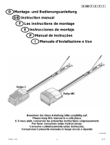
SET PANEL
1 Gear motor
2 Flashing light
3 Antenna
4 Key selector
5 Photocell
6 Sensor (pressureswitch)
7 Mechanic rubber safety bar
8 Warning board
9 Telescopic arm
10 Bracket
11 Drive shaft
12 Drive shafts supports
PRELIMINARY CHECKS
1
2
3
5
6
7
9
5
8
10
4
11
9
11
12
12
GB
114
119
LISTAS DE PIEZAS DE REPUESTO
Before you begin with installation, we suggest to check following operations:
1_ Read with attention the instructions and follow described installation sequences.
2_ Motor must not be set in action in rooms containing inflammable gas or liquids.

Carefully read all instructions prior to installation. Failure to observe the above
instructions, improper use or connection errors may impair the safety or correct
operation of the device and consequently the entire system.
The manufacturer declines all liability for malfunctions and/or damage caused
by failure to observe instructions and specifications.
The company reserves the right to apply modifications for product improvements.
OVERALL DIMENSION
Rotate the release lever
clockwise through 180°.
73
63
16
14
14
665
580
140
140
143
MANUAL OPERATION
118
115
E
Prohibición de la puesta en marcha antes de que la máquina
en la que se incorporará se haya declarado conforme con las
disposiciones de la norma CEE 98/37/CEE
MANTENIMIENTO
ELIMINACION
RECOMENDACIONES FINALES
PELIGRO: para cualquier tipo de mantenimiento, cortar la alimentación.
Para cualquier defecto de funcionamiento, para reparaciones,
mantenimientos o regulaciones se recomienda valerse de personal
cualificado.
Periódicamente limpiar y liberar de los desechos el riel de guía y
las ruedas relativas.
1.Efectuar la puesta a tierra.
2.Mantener siempre separados los cables de alimentación de los cables de mando.
3.Equipar la instalación con dispositivos de seguridad como: -fotocélulas.
- limitadores de par
- perfil de seguridad
sensible
Cuando la instalación da a una calle pública, es necesario instalar al menos dos de
los dispositivos arriba citados (elegidos entre tres tipos o también del mismo tipo).
4.Realizar la instalación según las normas vigentes.
5.El control de la fuerza de empuje debe ser realizada por la presencia de un
regulador de par en la instalación.
6.Todos los trabajos de mantenimiento, reparación y regulación deben ser
efectuadas por personal cualificado.
La eliminación de los materiales se realiza respetando las normas vigentes.
3_ Overhead door's structure must be solid and suitable.
4_ During run, motor for overhead door must not have friction or vibration.
5_ Garage door must open and close only through traction/compression
(without upsetting or rotation)
6_ Take off closing blocking-latch of motor.

116
117
fig. 4
fig. 5
80 mm
20 mm
fig. 6
INSTALLATION
5mm
5mm
100
50
The automation with single motor for central
assembly is recommended for garage doors
with dimensions less than or equal to 9 m2.
For larger dimensions or garage doors with
central doors, the installation of two lateral
motors is recommended (picture 1). In this
case, a microswitch is installed on the door
to avoid opening during operation.
1 > Locate the rotation axis of the garage door
and set the new axis, parallel to the first and
passing below at a
distance of 100 mm if a straight arm is
installed (picture 2), or 50 mm if a curved
arm is installed (picture 3).
2 > secure the gearmotor bracket by means
of welding or screws to the centre of the
garage door, and ensure that the axis of the
splined shaft protruding from the gearmotor
is aligned with the previously located axis.
fig. 1
fig. 2
fig. 3
ASSE DI
ROTAZIONE
GB
3.Fijar con soldadura el soporte de fijación del
brazo telescópico en el travesaño superior de
la puerta basculante o en la pared al lado de
la puerta (fig. 4).
4.Introducir y fijar el brazo telescópico en el
soporte de fijación recién montado. El brazo
telescópico debe posicionarse para poder
pasar entre el montante y el brazo de la puerta
basculante. En caso de que dicha distancia
fuera inferior a 15 mm, utilizar el brazo
telescópico curvado que hará posible el
movimiento.
5.Introducir el extremo con buje del tubo en el
árbol acanalado que sale del motorreductor.
Luego introducir el perno L en el otro extremo
del tubo.
6.Después de haber controlado que el tubo sea
perfectamente horizontal y después de haberlo
alineado con el brazo telescópico, cortar su
parte sobrante.
7.Luego de haber llevado la puerta basculante
en posición de máxima apertura, cortar la parte
superior del brazo telescópico para que no
interfiera con la parte inferior.
8.Después de haber llevado la puerta
basculante en posición baja, soldar la base
del tubo en la parte inferior del brazo
telescópico.
En caso de que fuera instalado el brazo
telescópico con hierro redondo perforado,
perforar el tubo siguiendo las indicaciones
en la fig. 6, hacer penetrar el hierro redondo
en el tubo y fijarlos utilizando los tornillos
adjuntos.
9.Introducir y fijar definitivamente el brazo
telescópico en el soporte de fijación. En fin
fijar el perno L (introducido en el tubo) en la
puerta basculante a una distancia adecuada
del brazo telescópico.
10.Para el lado opuesto de la puerta basculante
repetir las operaciones descritas desde el
punto 3 hasta el 9.
11.Si fuera necesario reequilibrar la puerta
aumentando los contrapesos (3 kg. aprox.
por lado) o el tensado de los muelles para
que las maniobras sean de fácil ejecución.

116
117
fig. 4
fig. 5
80 mm
20 mm
fig. 6
INSTALACION
5mm
5mm
100
50
La automatización con un solo motor
de montaje central se aconseja para
portones basculantes de dimensiones
inferiores o iguales a 9 m2. Para
dimensiones superiores o para portones
basculantes con puerta central se
aconseja la instalación de dos motores
laterales (fig. 1). En este último caso
se instala en la puerta un microinterruptor
de seguridad, para evitar su apertura
durante el funcionamiento de la misma.
1.Localizar el eje de rotación de la puerta
basculante y determinar el nuevo eje,
paralelo al primero y pasante por debajo
del mismo a una distancia de 100 mm si
se instala el brazo recto (fig. 2), de
50 mm si se instala el brazo curvado (fig. 3).
2.Fijar con soldadura o con tornillos el
soporte del motorreductor en el centro
del portón basculante, asegurándose
de que el eje del árbol acanalado que
sale del motorreductor coincida con el
eje localizado anteriormente.
fig. 1
fig. 2
fig. 3
ASSE DI
ROTAZIONE
E
3 > Secure the telescopic arm fixing bracket
by means of welding or screws to the upper
beam of the garage door or on the wall next to
the door (picture 4).
4 > Insert and secure the telescopic arm on
the fixing bracket previously installed.
Position the arm so that it passes between the
upright and the arm of the garage door. If this
distance is less than 15 mm, use the
curved telescopic arm to ensure correct
movements.
5 > Insert the end of the tube with the bushing
into the splined shaft protruding from the
gearmotor. Then insert the L bracket in the
other end of the tube
6 > After ensuring that the tube is perfectly
horizontal and aligned with the telescopic arm,
cut off any excessive section.
7 > After setting the garage door to the maximum
opening position, cut the upper section of the
telescopic arm so that it does not interfere
with the lower section.
8 > After moving the garage door to the
lowered position, weld the base of the tube
to the lower section of the telescopic arm. If the
telescopic arm with drilled bar is installed, drill
the tube as shown in fig.6, insert the bar into
the tube and secure by means of the screws
supplied.
9 > Insert and make the final fixture of the
telescopic arm on the fixing bracket. Then
secure the L bracket (inserted in tube) to the
garage door at an adequate distance from
the telescopic arm.
10 > Repeat the operations described in
points 3 to 9 for the opposite side of the
garage door.
11 > If necessary, re-balance the door by
increasing the counterweights (approx.
3 Kg per side) or tension the
springs, so that movements are smooth
and simple.

Es oportuno leer atentamente las instrucciones antes de efectuar la instalación.
La falta de observancia de las instrucciones arriba citadas, el uso impropio o
un error de conexión podría perjudicar la seguridad o el funcionamiento
correcto del dispositivo y por lo tanto de toda la instalación.
Se rechaza toda responsabilidad por posibles funcionamientos incorrectos y/o
daños causados por su inobservancia.
La empresa se reserva el derecho de llevar modificaciones al producto.
DIMENSIONES TOTALES
Girar la palanca de
desbloqueo en sentido
horario de 180°.
2.El aparato no debe accionarse en ambientes donde haya gases/líquidos inflamables.
3.La estructura del portón basculante debe ser sólida y adecuada.
4.Durante la carrera, el portón basculante no debe tener puntos de fricción o vibraciones.
5.La puerta del garaje debe abrirse y cerrarse exclusivamente mediante la fuerza
de tracción/compresión (sin movimientos de vuelco o de rotación).
6.Eliminar el posible pestillo de bloqueo del portón basculante en el cierre.
73
63
16
14
14
665
580
140
140
143
FUNCIONAMIENTO MANUAL
118
115
GB
Dispose of all materials in compliance with current regulations.
MAINTENANCE
DANGER: disconnect the power supply before any maintenance operations.
In the event of malfunctions, ensure exclusively qualified personnel perform
repairs, maintenance or adjustments.
Periodically clean and remove all residue from the guide tracks and wheels.
DISPOSAL
RECOMMENDATIONS
1 > Ensure connection of an efficient earthing system
2 > Always keep power supply cables separate from control cables.
3 > Ensure the plant is fitted with safety devices such as:
- photocells
- torque limiters
- safety edge
If the system gives access to a public way, at least two of the above devices should
be installed (three types or three
of the same).
4 > Ensure system set-up in compliance with current regulations.
5 > The starting torque must be provided by a torque regulator installed in
the system.
6 > All maintenance, repairs, and adjustments must be performed by qualified
personnel.
It is strictly forbidden to start up the device until the machine in
which it is incorporated is declared compliant to the
EEC Directive 98/37/CEE.

6
12
6
3
6
10
MODELOS Y CARACTERÍSTICAS
DATOS TECNICOS
CENTRALITA
ALIMEN TACION
POTENCIA ABSORBIDA
ABSORBCION DEL MOTOR
CONDENSADOR
GRADO DE PROTECCION
VELOCIDAD
DIMENSIONES MAX. DE LA REJA
CLASE DE AISLAMIENTO
SERVICIO TEMPORANEO
TEMPERATURA DE
FUNCIONAMIENTO
PESO
900BS-50N
900BS-50CL
900BS-50-24
900BS-50C
Motorreductor electromecánico irreversible, 230Vac para
portones basculantes de muelles o de contrapesos de
dimensiones hasta 9 m2.
Motorreductor electromecánico irreversible, 230Vac equipado con
centralita (CT-1A) para portones basculantes de muelles o de
contrapesos de dimensiones hasta 9 m2.
GB
BS-50N BS-50CL BS-50C BS-50-24
SPARE PARTS LIST
-
230VAC
340W
1,5 A
12,5
IP 43
0,76 M/S
9MQ
I
30%
-20°/+70°
14 KG
µF
CT-24
24VDC
150W
6A
-
IP 43
0,80 M/S
9MQ
I
80%
-20°/+70°
13,8 KG
CT 1A
230VAC
340W
1,4 A
12,5
IP 43
0,76 M/S
9MQ
I
30%
-20°/+70°
14 KG
µF
CT 1E
230VAC
340W
1,5 A
12,5
IP 43
0,76 M/S
9MQ
I
30%
-20°/+70°
14 KG
µF
1 390V6X90TCE
2 500SEMBS-501
3 450GBS-50
4 440C6302
5 570CBSS
6 490A+CD69Z44
7 440CUFCU
8 570CAST
9 490ALSBBS
10 440C6205
11 410AD25
12 350PE14VIM
13 410AD10
14 490A+C180
15 490CD87756
16 440C6201
17 430MBS
18 410L8X7X35
19 480CD39Z29
20 410AD18
21 490PSB70I
22 490PSB10X118E
23 490LSB10848
24 390V4X25C + 400DM4
25 500MANBS-50
26 470S9050H604
27 440C6203
28 470R5060M1.25
29 550CABBS-50
30 390V6X80TCE
31 400DM6
32 390V6X35TCE
33 500SEMBS-50
34 380OC2-5G
35 570CAMMBS
36 390V3X12S
37 190CR125M450
38 570CLCOR
39 330M16AW3R5+330P161J
40 390V2-9X16C
BS-50N
BS-50CL
BS-50C
BS-50-24
1 390V6X90TCE
2 500SEMBS-501
3 450GBS-50
4 440C6302
5 570CBSS
6 490A+CD69Z44
7 440CUFCU
8 570CAST
9 490ALSBBS
10 440C6205
11 410AD25
12 350PE14VIM
13 410AD10
14 490A+C180
15 490CD87756
16 440C6201
17 430MBS
18 410L8X7X35
19 480CD39Z24
20 410AD18
21 490PSB70I
22 490PSB10X118E
23 490LSB10848
24 390V4X25C + 400DM4
25 500MANBS-50
26 470MOBSENC
29 550CABBS-50
30 390V6X80TCE
31 400DM6
32 390V6X35TCE
33 500SEMBS-50
34 380OC2-5G
35 570CAMMBS
36 390V3X12S
38 570CLCOR
39 330M16AW3R5+330P161J
40 390V2-9X16C

6
12
6
3
6
10
MODELS AND SPECIFICATIONS
DONNÉES TECHNIQUES
CENTRALE
ALIMENTATION
PUISSANCE ASSORBEE
ABSORPTION MOTEUR
CONDENSATEUR
DEGRÉ DE PROTECTION
VITESSE
DIMENTIONS MAX. PORTAI
CLASSE D’ISOLEMENT
SERVICE TEMPORAIRE
TEMPÉRATURE DE
FONCTIONNEMENT
POIDS
900BS-50N
900BS-50CL
900BS-50-24
900BS-50C
Motoréducteur électromécanique irréversible 230Vca pour la
motorisation des portes basculantes jusqu'à 9 m2 à compensation
par ressorts ou contrepoids
Motoréducteur électromécanique irréversible 230Vca fourni avec
centrale de commande (CT-1A) (autrement dit coffret de
commande) pour la motorisation des portes jusqu'à 9 m2
équilibrées par contrepoids ou ressorts.
D
BS-50N BS-50CL BS-50C BS-50-24
ERSATZTEILVERZEICHNIS
-
230VAC
340W
1,5 A
12,5
IP 43
0,76 M/S
9MQ
I
30%
-20°/+70°
14 KG
µF
CT-24
24VDC
150W
6A
-
IP 43
0,80 M/S
9MQ
I
80%
-20°/+70°
13,8 KG
CT 1A
230VAC
340W
1,4 A
12,5
IP 43
0,76 M/S
9MQ
I
30%
-20°/+70°
14 KG
µF
CT 1E
230VAC
340W
1,5 A
12,5
IP 43
0,76 M/S
9MQ
I
30%
-20°/+70°
14 KG
µF
1 390V6X90TCE
2 500SEMBS-501
3 450GBS-50
4 440C6302
5 570CBSS
6 490A+CD69Z44
7 440CUFCU
8 570CAST
9 490ALSBBS
10 440C6205
11 410AD25
12 350PE14VIM
13 410AD10
14 490A+C180
15 490CD87756
16 440C6201
17 430MBS
18 410L8X7X35
19 480CD39Z29
20 410AD18
21 490PSB70I
22 490PSB10X118E
23 490LSB10848
24 390V4X25C + 400DM4
25 500MANBS-50
26 470S9050H604
27 440C6203
28 470R5060M1.25
29 550CABBS-50
30 390V6X80TCE
31 400DM6
32 390V6X35TCE
33 500SEMBS-50
34 380OC2-5G
35 570CAMMBS
36 390V3X12S
37 190CR125M450
38 570CLCOR
39 330M16AW3R5+330P161J
40 390V2-9X16C
BS-50N
BS-50CL
BS-50C
BS-50-24
1 390V6X90TCE
2 500SEMBS-501
3 450GBS-50
4 440C6302
5 570CBSS
6 490A+CD69Z44
7 440CUFCU
8 570CAST
9 490ALSBBS
10 440C6205
11 410AD25
12 350PE14VIM
13 410AD10
14 490A+C180
15 490CD87756
16 440C6201
17 430MBS
18 410L8X7X35
19 480CD39Z24
20 410AD18
21 490PSB70I
22 490PSB10X118E
23 490LSB10848
24 390V4X25C + 400DM4
25 500MANBS-50
26 470MOBSENC
29 550CABBS-50
30 390V6X80TCE
31 400DM6
32 390V6X35TCE
33 500SEMBS-50
34 380OC2-5G
35 570CAMMBS
36 390V3X12S
38 570CLCOR
39 330M16AW3R5+330P161J
40 390V2-9X16C

6
12
6
3
6
10
MODELLE UND EIGENSCHAFTEN
TECHNISCHE DATEN
MOTORSTEUERUNG
STROMVERSORGUNG
LEISTUNG
MOTORLEISTUNG
KONDENSATOR
SCHUTZSTUFE
GESCHWINDIGKEIT
TORMAßEN
ISOLIERUNGSKLASSE
PROVIESORISCHER DIENST
ARBEITSTEMPERATUR
GEWICH
900BS-50N
900BS-50CL
900BS-50-24
900BS-50C
Unwiderrufliches, elektromechanisches Getriebe, 230Vac für
Schwinggitter mit Federn oder Gegengewicht, für Max. 9 qm Größe.
Elektromechanischer Torantrieb, nicht umkehrbar, 230VAC
komplett mit Steuergerät (CT-1A) für Kipptore mit Federn oder
Gegengewichten und Abmessungen bis zu 9 m2.
F
BS-50N BS-50CL BS-50C BS-50-24
LISTE DES PIEÈCES DÈTACHÉES
-
230VAC
340W
1,5 A
12,5
IP 43
0,76 M/S
9MQ
I
30%
-20°/+70°
14 KG
µF
CT-24
24VDC
150W
6A
-
IP 43
0,80 M/S
9MQ
I
80%
-20°/+70°
13,8 KG
CT 1A
230VAC
340W
1,4 A
12,5
IP 43
0,76 M/S
9MQ
I
30%
-20°/+70°
14 KG
µF
CT 1E
230VAC
340W
1,5 A
12,5
IP 43
0,76 M/S
9MQ
I
30%
-20°/+70°
14 KG
µF
1 390V6X90TCE
2 500SEMBS-501
3 450GBS-50
4 440C6302
5 570CBSS
6 490A+CD69Z44
7 440CUFCU
8 570CAST
9 490ALSBBS
10 440C6205
11 410AD25
12 350PE14VIM
13 410AD10
14 490A+C180
15 490CD87756
16 440C6201
17 430MBS
18 410L8X7X35
19 480CD39Z29
20 410AD18
21 490PSB70I
22 490PSB10X118E
23 490LSB10848
24 390V4X25C + 400DM4
25 500MANBS-50
26 470S9050H604
27 440C6203
28 470R5060M1.25
29 550CABBS-50
30 390V6X80TCE
31 400DM6
32 390V6X35TCE
33 500SEMBS-50
34 380OC2-5G
35 570CAMMBS
36 390V3X12S
37 190CR125M450
38 570CLCOR
39 330M16AW3R5+330P161J
40 390V2-9X16C
BS-50N
BS-50CL
BS-50C
BS-50-24
1 390V6X90TCE
2 500SEMBS-501
3 450GBS-50
4 440C6302
5 570CBSS
6 490A+CD69Z44
7 440CUFCU
8 570CAST
9 490ALSBBS
10 440C6205
11 410AD25
12 350PE14VIM
13 410AD10
14 490A+C180
15 490CD87756
16 440C6201
17 430MBS
18 410L8X7X35
19 480CD39Z24
20 410AD18
21 490PSB70I
22 490PSB10X118E
23 490LSB10848
24 390V4X25C + 400DM4
25 500MANBS-50
26 470MOBSENC
29 550CABBS-50
30 390V6X80TCE
31 400DM6
32 390V6X35TCE
33 500SEMBS-50
34 380OC2-5G
35 570CAMMBS
36 390V3X12S
38 570CLCOR
39 330M16AW3R5+330P161J
40 390V2-9X16C
/