JET Taper Attachment Owner's manual
- Category
- Lathes
- Type
- Owner's manual
This manual is also suitable for

Assembly Instructions and Parts Manual
Taper Attachment for Bench Lathes
Model TAK-13GH/BD
JET
427 New Sanford Road
LaVergne, Tennessee 37086 Part No. M-321442
Ph.: 800-274-6848 Revision B 03/2014
www.jettools.com Copyright © 2014 JET

2
Warranty and Service
JET warrants every product it sells against manufacturers’ defects. If one of our tools needs service or repair, please
contact Technical Service by calling 1-800-274-6846, 8AM to 5PM CST, Monday through Friday.
Warranty Period
The general warranty lasts for the time period specified in the literature included with your product or on the official
JET branded website.
• JET products carry a limited warranty which varies in duration based upon the product. (See chart below)
• Accessories carry a limited warranty of one year from the date of receipt.
• Consumable items are defined as expendable parts or accessories expected to become inoperable within a
reasonable amount of use and are covered by a 90 day limited warranty against manufacturer’s defects.
Who is Covered
This warranty covers only the initial purchaser of the product from the date of delivery.
What is Covered
This warranty covers any defects in workmanship or materials subject to the limitations stated below. This warranty
does not cover failures due directly or indirectly to misuse, abuse, negligence or accidents, normal wear-and-tear,
improper repair, alterations or lack of maintenance.
Warranty Limitations
Woodworking products with a Five Year Warranty that are used for commercial or industrial purposes default to a
Two Year Warranty. Please contact Technical Service at 1-800-274-6846 for further clarification.
How to Get Technical Support
Please contact Technical Service by calling 1-800-274-6846. Please note that you will be asked to provide proof
of initial purchase when calling. If a product requires further inspection, the Technical Service representative will
explain and assist with any additional action needed. JET has Authorized Service Centers located throughout the
United States. For the name of an Authorized Service Center in your area call 1-800-274-6846 or use the Service
Center Locator on the JET website.
More Information
JET is constantly adding new products. For complete, up-to-date product information, check with your local distributor
or visit the JET website.
How State Law Applies
This warranty gives you specific legal rights, subject to applicable state law.
Limitations on This Warranty
JET LIMITS ALL IMPLIED WARRANTIES TO THE PERIOD OF THE LIMITED WARRANTY FOR EACH PRODUCT.
EXCEPT AS STATED HEREIN, ANY IMPLIED WARRANTIES OF MERCHANTABILITY AND FITNESS FOR A
PARTICULAR PURPOSE ARE EXCLUDED. SOME STATES DO NOT ALLOW LIMITATIONS ON HOW LONG AN
IMPLIED WARRANTY LASTS, SO THE ABOVE LIMITATION MAY NOT APPLY TO YOU.
JET SHALL IN NO EVENT BE LIABLE FOR DEATH, INJURIES TO PERSONS OR PROPERTY, OR FOR
INCIDENTAL, CONTINGENT, SPECIAL, OR CONSEQUENTIAL DAMAGES ARISING FROM THE USE OF OUR
PRODUCTS. SOME STATES DO NOT ALLOW THE EXCLUSION OR LIMITATION OF INCIDENTAL OR
CONSEQUENTIAL DAMAGES, SO THE ABOVE LIMITATION OR EXCLUSION MAY NOT APPLY TO YOU.
JET sells through distributors only. The specifications listed in JET printed materials and on official JET website are
given as general information and are not binding. JET reserves the right to effect at any time, without prior notice,
those alterations to parts, fittings, and accessory equipment which they may deem necessary for any reason
whatsoever. JET
®
branded products are not sold in Canada by JPW Industries, Inc.
Product Listing with Warranty Period
90 Days – Parts; Consumable items; Light-Duty Air Tools
1 Year – Motors; Machine Accessories; Heavy-Duty Air Tools; Pro-Duty Air Tools
2 Year – Metalworking Machinery; Electric Hoists, Electric Hoist Accessories; Woodworking Machinery used
for industrial or commercial purposes
5 Year – Woodworking Machinery
Limited Lifetime – JET Parallel clamps; VOLT Series Electric Hoists; Manual Hoists; Manual Hoist
Accessories; Shop Tools; Warehouse & Dock products; Hand Tools
NOTE: JET is a division of JPW Industries, Inc. References in this document to JET also apply to JPW Industries,
Inc., or any of its successors in interest to the JET brand.

3
Warnings
For your own safety, read this instruction manual before operating the tool.
Wear Eye Protection
• KEEP GUARDS IN PLACE and in working order.
• REMOVE ADJUSTING KEYS AND WRENCHES. Form the habit of checking to see that keys and
adjusting wrenches are removed from the tool before turning it on.
• KEEP THE WORK AREA CLEAN. Cluttered areas and benches invite accidents.
• DO NOT USE IN A DANGEROUS ENVIRONMENT. Don’t use power tools in damp or wet
locations, or expose them to rain. Keep work area well lighted.
• KEEP CHILDREN AWAY. All visitors should be kept safe distance from the work area.
• MAKE THE WORKSHOP KID PROOF with padlocks, master switches, or by removing starter keys.
• DON’T FORCE THE TOOL. It will do the job better and safer at the rate for which it was designed.
• USE THE RIGHT TOOL. Don’t force a tool or attachment to do a job for which it was not designed.
• USE THE PROPER EXTENSION CORD. Make sure you extension cord is in good condition.
When using an extension cord, be sure to use one heavy enough to carry the current your product
will draw. An undersized cord will cause a drop in the line voltage resulting in loss of power and
overheating. For runs up to 25 feet, use a 14 AWG or larger gauge cord. For runs up to 50
feet, use a 12 AWG or larger cord. Runs over 50 feet are not recommended. If in doubt, use
the next heavier gauge. The smaller the gauge number, the heavier the cord.
• WEAR PROPER APPAREL. Do not wear loose clothing, gloves, neckties, rings, bracelets, or other
jewelry which may get caught in moving parts. Nonslip footwear is recommended. Wear protective
hair covering to contain long hair.
• ALWAYS USE SAFETY GLASSES. Also use face or dust masks if the cutting operation is dusty.
Everyday eyeglasses only have impact resistant lenses, they are NOT safety glasses.
• SECURE WORK. Use clamps or a vise to hold the work when its practical. It’s safer than using
your hand and it frees both hands to operate the tool.
• DON’T OVERREACH. Keep proper footing and balance at all times.
• MAINTAIN TOOLS WITH CARE. Keep tools sharp and clean for best and safest performance.
Follow instructions for lubricating and changing accessories.
• DISCONNECT TOOLS before servicing; when changing accessories, such as blades, bits cutters,
and the like.
• REDUCE THE RISK OF UNINTENTIONAL STARTING. Make sure the switch is in the off position
before plugging in the machine.
• USE RECOMMENDED ACCESSORIES. Consult the owner’s manual for recommended
accessories. The use of improper accessories may cause a risk of injury.
• NEVER STAND ON A TOOL. Serious injury could occur if the tool is tipped or if the cutting tool is
unintentionally contacted.
• CHECK DAMAGED PARTS. Before further use of the tool, a guard or other part that is damaged
should be carefully checked to determine that it will operate properly and perform its intended
function. Check for alignment of moving parts, binding of moving parts, breakage of parts,
mounting, and any other conditions that may affect its operation. A guard or other part that is
damaged should be properly repaired or replaced.
• DIRECTION OF FEED. Feed work into a blade or cutter against the direction of rotation of the
blade or cutter only.
• NEVER LEAVE THE TOOL RUNNING UNATTENDED. TURN THE POWER OFF. Don’t leave the
tool until it comes to a complete stop.

4
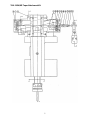
Introduction
The TAK-13GH/BD Taper Attachment is designed to produce accurate tapers up to 10” long and 20 degree
included angle at any distance from the spindle nose.
The attachment is easy to set, is always ready for use, and has two sets of graduations – one in degrees of
taper, the other in inches per foot (10 degrees both sides of center line and 4” per feet).
The telescopic screw turns on two thrust bearings in the taper slide and does not interfere with regular use of
the cross slide.
To realize the highest precision from the TAK-13GH/BD taper attachment, great care must be taken to ensure
that it is correctly mounted.
Please read this manual carefully before mounting and operating the attachment.
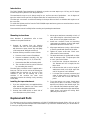
Mounting instructions
Note: Numbers in parentheses refer to item
numbers in the parts breakdown.
1. Remove all contents from the shipping
container and clean all rust protected parts
with kerosene or parts cleaner. Dry and lightly
oil all components with light machine oil.
2. Remove existing crossfeed screw as follows:
a. Remove screw in center of handwheel.
b. Remove handwheel assembly, dial, key
and bearing (#20, 21, 22, 23, 33 and 35).
c. Remove bracket (#30) and bearing (#19).
d. The crossfeed screw can now be removed
by unscrewing the nut (#17).
The telescoping crossfeed screw is supplied with a
brass nut. This nut can be used or the existing nut
supplied with the machine can be used. If the
machine is new, use the existing nut in the
machine. If the machine has been used
extensively, remove the existing nut by removing
screw (#26).
Installing the taper attachment
1. If you are using the brass nut supplied with the
taper attachment, install it now. Note: Install
screw but do not tighten at this time
2. Remove dust shield (#104) on back side of
cross slide (two cross point screws).
3. Mount taper attachment assembly to back of
cross slide using four socket head screws (#4).
Note: Do not securely tighten at this time.
4. Install new crossfeed screw and remaining
components per drawing enclosed with taper
attachment. (Reference section A-A.)
5. Align taper attachment (using a dial indicator)
so that it is parallel with the bed of the lathe.
6. Tighten all screws at this time. Check cross
slide screw for free movement.
7. The taper attachment is supplied with no index
mark on the taper slide. To adjust taper slide
to “zero”, proceed as follows:
a. Insert test bar (minimum dimensions of
3/4" diameter and 18” in length) into the
lathe chuck.
b. Indicate test bar end to end (or length of
attachment travel) and adjust taper bar
until “0” degree run-out is obtained.
c. Lock taper bar to prevent movement and
stake an index mark at “0” degrees. This
can be done with a small cold chisel or
punch.
8. To use the lathe to cut a taper, simply attach
locking block (#55) to the bed. Loosen the
taper bar and adjust to the desired angle. The
cross slide will now follow the taper bar angle.
9. To use the lathe without the taper attachment,
simply loosen and swing the locking block
(#55) away from the bed.
Replacement Parts
To order parts or reach our service department, call 1-800-274-6848 Monday through Friday, 8:00 a.m. to 5:00
p.m. CST. Having the Model Number and Serial Number of your machine available when you call will allow us
to serve you quickly and accurately.

5
TAK-13GH/BD Taper Attachment Kit

6
TAK-13GH/BD Taper Attachment Kit

7
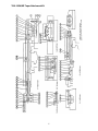
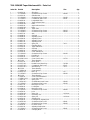
TAK-13GH/BD Taper Attachment Kit – Parts List
Index No Part No Description Size Qty
1 ................ 84-0001-00 ................ Slide Base................................................................ ...................................... 1
2 ................ TS-1504081 .............. Socket Head Cap Screw.......................................... M8x40 ........................... 4
3 ................ 84-1001-00 ................ Slide Bracket............................................................ ...................................... 1
4 ................ TS-1504061 .............. Socket Head Cap Screw.......................................... M4x30 ........................... 4
5 ................ TS-1532021 .............. Countersunk Flat Screw .......................................... M4x8 ............................. 6
6 ................ 84-0003-00 ................ Longitudinal Slide .................................................... ...................................... 1
7 ................ 84-0004-00 ................ Taper Indicator Plate ............................................... ...................................... 1
8 ................ 84-0004-00-1............. Rivet......................................................................... ...................................... 2
9 ................ 84-0005-00 ................ Angle Indicator Plate................................................ ...................................... 1
10 .............. 84-0005-00-1............. Rivet......................................................................... ...................................... 2
11 .............. 84-0006-00 ................ Taper Slide .............................................................. ...................................... 1
12 .............. TS-1503031 .............. Socket Head Cap Screw.......................................... M6x12 ........................... 1
13 .............. TS-1503051 .............. Socket Head Cap Screw.......................................... M6x20 ........................... 1
14 .............. 84-0007-00 ................ A xle .......................................................................... ...................................... 1
15 .............. 84-0008-00 ................ Gib Strip ................................................................... ...................................... 1
16 .............. 84-0006-00 ................ Adjusting Screw ....................................................... ...................................... 2
17 .............. 84-0100-00 ................ Adjusting Piece ........................................................ ...................................... 1
18 .............. 84-0011-00 ................ Adjusting Screw ....................................................... ...................................... 1
19 .............. 84-0012-00 ................ Adjusting Knob......................................................... ...................................... 1
20 .............. 84-0012-00-1............. Spring Pin ................................................................ 3x14 .............................. 1
21 .............. 84-0013-00 ................ Clamping Piece........................................................ ...................................... 1
22 .............. 84-1002-00 ................ Taper Slide Rest ...................................................... ...................................... 1
23 .............. 84-0015-00 ................ Gib Strip ................................................................... ...................................... 1
24 .............. 84-0016-00 ................ Adjusting Screw ....................................................... ...................................... 2
25 .............. 84-1003-00 ................ Cross Slide Block..................................................... ...................................... 1
26 .............. TS-1501061 .............. Socket Head Cap Screw.......................................... M4x20 ........................... 2
27 .............. 84-1004-00 ................ Feed Block ............................................................... ...................................... 1
29 .............. 84-1005-00 ................ Dust Cover ............................................................... ...................................... 1
30 .............. 84-1006-2/2-00.......... Cross Feed Screw ................................................... 10 TPI ........................... 1
31 .............. BB-51101 .................. Thrust Bearing ......................................................... ...................................... 2
32 .............. 84-1007-00 ................ Pinion Shaft ............................................................. ...................................... 1
33 .............. 84-1007-00-1............. Double Round Head Key ......................................... 5x5x30 .......................... 1
34 .............. 84-1007-00-2............. Countersunk Flat Screw .......................................... M3x5 ............................. 1
35 .............. 84-1007-00-3............. Woodruff Key ........................................................... 3x13 .............................. 1
36 .............. BB-55102 .................. Thrust Bearing ......................................................... ...................................... 1
37 .............. 17-0303A-00 ............. Cross Bracket .......................................................... ...................................... 1
38 .............. 84-0023-01-1............. Ball Cup ................................................................... 1/4” ................................ 1
39 .............. TS-1503051 .............. Socket Head Cap Screw.......................................... M6x20 ........................... 2
40 .............. BB-51102 .................. Thrust Bearing ......................................................... ...................................... 1
41 .............. 17-0304-00 ................ Cross Feed Handwheel ........................................... ...................................... 1
42 .............. 17-0356-2/2-00.......... Cross Dial Guard ..................................................... ...................................... 1
43 .............. 17-0357-00 ................ Spring Leaf .............................................................. ...................................... 1
44 .............. 17-0504-00-2............. Socket Button Head Screw ...................................... M8x20 ........................... 1
45 .............. TS-1522061 .............. Socket Head Set Screw ........................................... M5x20 ........................... 1
46 .............. 84-0027-00 ................ Bearing Dust Cover ................................................. ...................................... 1
47 .............. 84-0028-00 ................ Locking Nut .............................................................. ...................................... 1
48 .............. 84-1008-00 ................ Bearing Housing ...................................................... ...................................... 1
49 .............. TS-1504101 .............. Socket Head Cap Screw.......................................... M8x50 ........................... 2
50 .............. 84-0030-00 ................ Joint ......................................................................... ...................................... 1
51 .............. 84-0030-00-1............. Spring Pin ................................................................ 4x19 mm ....................... 1
52 .............. 84-0031-00 ................ Universal Joint ......................................................... ...................................... 1
53 .............. 84-0031-00-1............. Spring Pin ................................................................ 4x19 mm ....................... 1
54 .............. 84-0032-00 ................ Adjusting Bar ........................................................... ...................................... 1
55 .............. 84-1009-00 ................ Locking Block Adjusting Bar .................................... ...................................... 1
56 .............. 84-0033-00-1............. Socket Head Set Screw ........................................... M8x8 ............................. 1
57 .............. TS-1504041 .............. Socket Head Cap Screw.......................................... M8x20 ........................... 1
58 .............. 84-0034-00 ................ Eccentric Shaft......................................................... ...................................... 1
59 .............. 84-1010-00 ................ Adjusting Bar Bracket .............................................. ...................................... 1
60 .............. TS-1524011 .............. Socket Head Set Screw ........................................... M8x8 ............................. 1
61 .............. 84-0036-00 ................ Clamping Block ........................................................ ...................................... 1

8
Index No Part No Description Size Qty
62 .............. TS-1504101 .............. Socket Head Cap Screw.......................................... M8x50 ........................... 2
63 .............. 17-0308-00 ................ Bolt........................................................................... ...................................... 1
64 .............. 17-0307-00 ................ Handle ..................................................................... ...................................... 1
65 .............. 84-0039-00 ................ Indicator ................................................................... ...................................... 2
66 .............. 84-0039-00-1............. Rivet......................................................................... 2x5 mm ......................... 4
67 .............. 17-0323-2/2-00.......... Feed Nut .................................................................. ...................................... 1
68 .............. TS-1503041 .............. Socket Head Cap Screw.......................................... M6x16 ........................... 1
69 .............. 17-0305-2/2-00.......... Dual Dial .................................................................. ...................................... 1
70 .............. 17-0356-00-1............. Round Head Screw.................................................. M4x6 ............................. 2
71 .............. 84-0002-00-3............. Spring Pin ................................................................ 3x20 mm ....................... 2
72 .............. 84-0038-00 ................ Spacer ..................................................................... ...................................... 1
73 .............. 84-0021-00-2............. Lock W asher ............................................................ AW #12 .......................... 1
74 .............. 17-0306-00 ................ Washer .................................................................... ...................................... 1
-
 1
1
-
 2
2
-
 3
3
-
 4
4
-
 5
5
-
 6
6
-
 7
7
-
 8
8


JET Taper Attachment Owner's manual
- Category
- Lathes
- Type
- Owner's manual
- This manual is also suitable for
Ask a question and I''ll find the answer in the document
Finding information in a document is now easier with AI
Related papers
-
JET GH-1440B Owner's manual
-
-
JET GHB-1340A Owner's manual
-
-
-
JET 322840 Owner's manual
-
-
-
-