
TRADEMARK
All products and company names are trademarks or
registered trademarks of their respective holders.
These specifications are subject to change without
notice.
Manual Revision 1.2
February 10, 1997
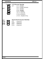
KP6-LS (SMP)
A Dual Pentium® II Processor based
AGP motherboard

FeaturesKP6-LS
Page 2
FEATURES
KP6-LS Features:
•KP6-LS is based on the Dual Pentium
®
II Processor operating at 233 ~ 330
MHz on Slot 1. The board is configured by an Easy-Setting-Single-Jumper
(E.S.S.J.) to match your CPU clock speed.
•Designed with Intel’s 82443 LX AGPset.
•Supports up to 1 Gigabyte of DRAM (minimum of 8 MB) on board, You can
use 168-pin DIMM x 4. It will automatically detect Extended Data Output
(EDO) DRAM or Synchronous DRAM memory (SDRAM)
•KP6-LS will support Error Checking and Correcting (ECC) when using parity
DRAM memory modules. This will detect multiple bit errors and correct 1-bit
memory errors.
•Supports (3) 16 bit ISA slots, (4) 32 bit PCI slots, (1) AGP slot and provides
(2) independent high performance PCI IDE interfaces capable of supporting
PIO Mode 3/4 and Ultra DMA 33 devices. The KP6-LS supports (4) PCI
Bus Master slots and a jumperless PCI INT# control scheme which reduces
configuration confusion when plugging in PCI card(s).
•Supports ATAPI (e.g. CD-ROM) devices on both Primary and Secondary IDE
interfaces.
•Designed with Winbond W83977 Multi I/O: (1) floppy port, (1) parallel port
(EPP, ECP), and (2) serial ports (16550 Fast UART), (1) IrDA.
Note: Japanese “Floppy 3 mode” is also supported
•Includes a PS/2 mouse connector.
•Allows use of a PS/2 or AT keyboard.
•Features Award Plug & Play BIOS. With Flash Memory you can always
upgrade to the current BIOS as they are released. (http://www.
2themax.com/
please visit our Technical Support section for the latest updates)

FeaturesKP6-LS
Page 3
•KP6-LS utilizes a Lithium battery which provides environmental protection and
longer battery life.
•Supports the Universal Serial Bus (USB) connector. The onboard PIIX4 chip
provides the means for connecting PC peripherals such as; keyboards,
joysticks, telephones, and modems.
•Built-in ATX 20-pin power supply connector.
•Software power-down when using Windows
®
95.
•Supports ring-in feature (remote power-on through external modem,
allows system to be turned on remotely.
•Supports Wake On-
LAN (WOL).
•Resume by Alarm - Allows your system to turn on at a preselected time.
•Power Loss Recovery - In the event of a power outage your system will
automatically turn itself back on without user intervention.
• Supports CPU Hardware sleep and SMM (System Management Mode).
• Supports Desktop Management Interface (DMI) facilitating the management
of desktop computers, hardware and software components and peripherals,
whether they are stand-alone systems or linked into networks. (option)

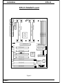
Installation KP6-LS
Page 4
1
Infrared
J2
J1
Chassis
Intrusion
JP3
Clear
CMOS
Secondary IDE
Primary IDE
1
1
J11
J12
FDD Connector
1
J13
PCI Slot #1
AGP SLOT
CPU Cartridge SLOT 1
PCI Slot #2
PCI Slot #3
PCI Slot #4
ISA Slot #1
ISA Slot #2
ISA Slot #3
Intel
443LX
PCIset
COM 1COM 2
USB 1
(Top)
Mouse
(Top)
USB 0
(Bottom)
PS/2
Keyboard
(Bottom)
KP6-LS
Rev. #
USB
Parallel Port
Primary
ATX Power Input
J9
Battery
Flash Memory
for BIOS
20 0M H z
26 6M H z
30 0M H z
33 0M H z
23 3M H z Default
JP7
DIMM 2
DIMM 1
Bank 0
Bank 1
DIMM 3
Bank 2
J4
J14
Intel
PIIX4
PCIset
Chassis
Fan
J3
CPU1
Fan
J4
LM79
Hardware
Monitor
Winbond
83977
I/Oset
JP1
1
JPX1 Wake On-Lan
Intel
82093A
P
W
J
P
J
P
J
P
J
P
R
S
S
L
S
P
T
B
H/
D
G/
L
K
E
DIMM 4
Bank 3
CPU Cartridge SLOT 1
Secondary
CPU2
Fan
J8
Figure 1
KP6-LS Detailed Layout

InstallationKP6-LS
Page 5
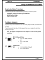
Easy Installation Procedure
Easy Installation Procedure
The following must be completed before powering on your new system:
Configure Jumpers to match your hardware
Install memory chips
Device Connectors
Configure Jumpers
2theMax designs all motherboards with the fewest jumpers to make your install fast
and easy.
The following will describe all of the jumpers that you are required to set before
moving on to step 2.
Note: The jumpers as depicted as shown (Figure 1) in their correct physical
orientation.
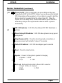
CMOS Clear
JP3: = 1-2 - Run Mode (Default)
= 2-3 - Clear CMOS
JP3:
1
BIOS Voltage Setting
JP1: = 1-2 - +5V Flash (Default)
4-5
= 2-3 - +12V Flash
5-6
4
1
JP1:
6
3

Installation KP6-LS
Page 6
CPU Processor Selection
JP7: = 1-2 - 200MHz
= 3-4 - 233MHz (Default)
= 5-6 - 266MHz
= 7-8 - 300MHz
= 9-10 - 330MHz
= 11-12 - Reserved
= 13-14 - Reserved
= 15-16 - Disable E.S.S.J.
JP7:
JP9:
JP10:
JP11:
JP12:
Reserved CPU Processor Selections
JP9: = Reserved
JP10: = Reserved
JP11: = Reserved
JP12: = Reserved
12
1516

InstallationKP6-LS
Page 7
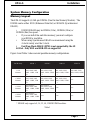
System Memory Configuration
Memory Layout
The KP6-LS supports (4) 168-pin DIMMs (Dual In-line Memory Module). The
DIMMs can be either EDO (Enhanced Data Out) or SDRAM (Synchronized
DRAM).
• DIMM SDRAM may be 83MHz (12ns), 100MHz (10ns) or
120MHz (8ns) bus speed.
• If you use both 50ns and 60ns memory you must configure
your BIOS to read 60ns.
• When using Synchronous DRAM we recommend using the
4 clock variety over the 2 clock.
• Fast Page Mode DRAM (FPM) is not supported by the LX
AGPset. Only EDO and SDRAM are supported.
Figure 2 and Table 1 show several possible memory configurations.
* SDRAM only supports 8, 16, 32, 64, 128MB DIMM modules.
Table 1
yromeMlatoT 1MMID 2MMID 3MMID 4MMID
BG1=
mumixaM
*MARDS/ODE
BM23,BM61,BM8
M652,BM821,BM46
1X
*MARDS/ODE
,BM23,BM61,BM8
BM652,BM821,BM46
1X
*MARDS/ODE
,BM23,BM61,BM8
BM652,BM821,BM46
1X
*MARDS/ODE
,BM23,BM61,BM8
BM652,BM821,BM46
1X
BM867=
mumixaM
*MARDS/ODE
BM23,BM61,BM8
M652,BM821,BM46
1X
*MARDS/ODE
,BM23,BM61,BM8
BM652,BM821,BM46
1X
*MARDS/ODE
,BM23,BM61,BM8
BM652,BM821,BM46
1X
enoN
BM215=
mumixaM
*MARDS/ODE
,BM23,BM61,BM8
BM652,BM821,BM46
1X
*MARDS/ODE
,BM23,BM61,BM8
BM652,BM821,BM46
1X
enoNenoN
BM652=
mumixaM
*MARDS/ODE
,BM23,BM61,BM8
BM652,BM821,BM46
1X
enoNenoNenoN

InstallationKP6-LS
Page 8
Device Connectors
Please install the motherboard into the chassis.
Now that your motherboard is installed you are ready to connect all your connec-
tions (figure 12).
USB 1
(Top)
USB 0
(Bottom)
PS/2 Mouse
(Top)
PS/2 Keyboard
(Bottom)
Parallel Port
(Top)
Com1Com2
(Bottom Left)(Bottom
Right)
J1:Chassis open monitoring(Reserved)
• A plug-in to monitor the chassis
J3:Chassis Fan Power
• A plug-in for the chassis Fan Power
J4:Chassis Panel Connector
• Keylock, Speaker, Reset, Turbo, Sleep, G/LED and HDD LED
J5:Floppy Controller
J6:Primary IDE
J7:Secondary IDE
J8:CPU 2 Fan Power
• A plug-in for the Power supply so that BIOS can monitor the RPM’s
J12:ATX Power Connector
• 20-pin power connector
J13:CPU 1 Fan Power
• A plug-in for the CPU Fan Power
JPX1:• WakeOn-
LAN (WOL)
Figure 12

InstallationKP6-LS
Page 9
Power On/Off - This is connected to the power button on the case.
Using the Soft-Off by Pwr-BTTN feature, you can choose either Instant
Off (turns system off
immediately), or 4 sec delay (you need to hold the
button down for 4 seconds before the system turns off). When the
system is in 4 sec delay mode, 2theMax has added a special feature to
make the system go into suspend mode when the button is pressed
momentarily.
J14
Device Connectors (continued)
Speaker - Connect to the system's speaker for beeping
1. Speaker 3. GND
2. N/C 4. GND
Reset - Closed to restart system.
Turbo LED indicator - LED ON when higher speed is selected
Sleep/Resume switch : Closed to enter sleep mode, a keystroke or
mouse movement will instantly "wake up" the system.
Power Saving LED indicator - LED ON when system is in any power
saving mode
IDE LED indicator - LED ON when Onboard PCI IDE Hard disks is
activate
KeyLock - Keyboard lock switch & Power LED connector
1. Power LED(+) 4. Keylock
2. N/C 5. GND
3. GND
J4
1
+
+
+
+
1
-
 1
1
-
 2
2
-
 3
3
-
 4
4
-
 5
5
-
 6
6
-
 7
7
-
 8
8
-
 9
9


