Page is loading ...

For any assistance or after sales service contact your
Davey Dealer. For help in locating your closest Dealer
contact your appropriate Davey Support Centre listed
on the back of this booklet.
• INSTALLATION
• OPERATION
•
TROUBLE SHOOT
ING
INSTALLATION
INSTRUCTIONS
WMTS-477:2016 Lic WM-022042

2
Davey commenced in 1934 and today, as Davey Water Products, manufactures and distributes
a comprehensive range of products for transfer, conservation, treatment and filtration of water.
Davey has a dominant market share in Australia and exports to more than 50 separate countries,
servicing some of the toughest environmental and climatic conditions on the globe.
Davey has maintained its commitment to research and development, resulting in innovative new
products servicing specific and emerging market opportunities. Many of these products have received
multiple awards for innovation and excellence which have led to our induction into the Manufacturing
Hall of Fame in Victoria.
Davey maintains leadership in quality with an environmental focus by holding ISO 9000-2001
accreditation and ISO 14000 environmental standard.
Davey is today a wholly owned subsidiary of GUD, a ‘Top 200’ Australian public company whose
shares are listed on the Australian Stock Exchange.
Now more than ever “Depend on Davey” reflects a business culture of dependable, innovative water
solutions when and where you need them, supported by the best service and advice.

3
CONTENTS
About RainBank. The easy way to save water. 4
Two types of installation - quick reference 5
How RainBank works 6
How to install RainBank 7
Before you start 9
Installation instruction 11
Pump outside tank option 12
Pump inside tank option 14
Float switch installation 18
Installation of Submersible Pumps 25
Priming Pumps 26
Maintaining RainBank 28
Trouble shooting RainBank 29
Warnings 32
Plumbers Tips 33
Davey Guarantee 35
Contact Details 36

4
m5
m5
m4
100,000 Litres
Congratulations on your purchase of
a high quality Australian made Davey
RainBank automatic water controller.
RainBank is patented and has been fitted
to thousands of homes.
• RainBank allows you to use water
from your rainwater tank for your
toilet, washing machine or garden
whenever there is water in the tank.
• If the tank water is exhausted
RainBank automatically and
seamlessly switches you over to
mains water.
• RainBank has an in-built “dual
check valve” for low hazard backflow
prevention.
RainBank can save up to 40% of
your home’s usage of mains water,
which could be up to 100,000 litres
of water a year.
Your actual savings depend on your roof
catchment area, rainfall and the size of
your tank.
RainBank may allow you to claim
tank rebates (when installed on
existing homes). Check with your
local water authority.
In some areas of Australia, having a
RainBank and using rainwater for your
toilet and washing machine allows you
to claim tank rebates paid by state
governments and some councils.
RainBank is energy efficient and
cheap to run.
Because RainBank only works when it is
needed it uses very little energy.
The daily power used to run a RainBank
and pump system supplying two toilets in
a three person dwelling is equivalent to:
• A reverse cycle air conditioner for
3 minutes
• A clothes dryer for 3 minutes
• A washing machine for 10 minutes
• A TV or PC for 30 minutes
ABOUT RAINBANK
THE EASY WAY TO SAVE WATER

5
6
6
1
2
5
1
2
3
In-tank Option Model No. KRBS1&2
3
5
6
9
4
7
Above Ground Option Model No. KRB1,2,3&4
9
4
Mains water supply
900kPa Maximum
1
3/4” BSP Male thread
2
3/4” BSP Male thread
3
Pump Power lead
4
RainBank Power lead
5
Stop valve
Warning:
Do not reconnect with
mains water supply
Important:
All pipework and outlet
fittings from RainBank must
be labelled to AS/NZS 3500.1
6
Float switch
7
Manual start button
8
Rainwater supply via pump
9
8
8
ABOVE GROUND OPTION
MODEL NO. KRB1, 2, 3 & 4
IN-TANK OPTION
MODEL NO. KRBS1 & 2
TWO TYPES OF
INSTALLATION
(see page 12) (see page 14)

6
1. When there is demand for water
from your toilet, washing machine or
garden tap, RainBank senses
this demand and checks the level of
water in the rainwater tank.
Note: demand must be greater than
1.5 litres per minute or mains water
will be delivered.
2. If there is rainwater in the tank
RainBank
switches on the pump.
The pressure of the pump is
sufficient to overcome the pressure of
the mains water inside RainBank
and this moves a plunger and allows
the rainwater to flow.
Note: mains water pressure
is not restricted.
3. When there is no longer a demand for
water, RainBank detects that water
has ceased to move inside the pipes,
switches off the pump and waits for
another water demand.
4. If RainBank senses a water
demand and detects insufficient
waterin the rainwater tank it will
automatically allow the mains water
to flow.
5. If there is a power failure during a
demand for water RainBank will
automatically supply the mains
water as backup.
What are the advantages of
RainBank over conventional
air-gap systems?
• RainBank is totally hands off and
needs no maintenance or adjustment.
• RainBank is easy to install.
• RainBank does not require mains
water to be re-pumped and
therefore saves energy.
• RainBank is WaterMark approved
– this means plumbing inspections
will be approved & your plumbers
insurance should cover installation
faults.
• RainBank will provide mains water
as backup when:
- there is no rainwater
- there is no electricity to run pump
- the pump has been removed for
servicing. Air-gap systems rely on
pumps to pressurise all water
and do not function without them.
HOW RAINBANK WORKS

7
IMPORTANT
Because it involves mains water,
RainBank may only be legally
installed by a licensed plumber.
Ensure mains water pressure is
limited to 600kPa.
NOTE: Because the effects of seasonal
change etc. can cause the
pump and tank to move slightly
relevant to the home it is highly
recommended that discharge
and/or suction pipe lines be fitted
with flexible pipe, such as braided
hose, reinforced suction hose or
polythene pipe.
Different types of RainBank
Installations
There are different ways a RainBank can
be installed depending on your rainwater
tank and pump configuration.
INSTALLATION TYPE 1 - PAGE 16
Tank: above ground
Pump: outside tank
Float switch: must be installed inside
of tank
Pump Kit: KRB1, 2, 3 & 4
INSTALLATION TYPE 2 - PAGE 21
Tank: above ground
Pump: submersible inside tank
Float switch: incorporated with pump
Pump Kit: KRBS1 & 2
INSTALLATION TYPE 3 - PAGE 22
Tank: below ground
Pump: submersible inside tank
Float switch: incorporated with pumps
Pump Kit: KRBS1 & 2
Mains In
To House
Mains In
To House
FS
HOW TO INSTALL RAINBANK
!
Mains In
To Hous
e

8
INSTALLATION TYPE 4 - PAGE 23
Tank: Below ground and at ground level
Float switch: Top entry
Pump Kit: KRB1, 2, 3 & 4
Different ways of installing the
RainBank unit itself.
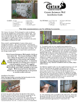
• Exposed installation against wall
(under eaves).
• Encased installation with unit and
pump inside cover.
• Integrated installation incorporated as
part of tank system.
FV
Mains In
To House
To House
Mains In
To House
Mains In
To House
Mains In

9
IMPORTANT:
• If you are in doubt about any aspect
of your RainBank kit’s suitability,
check with your Davey Dealer. For
help in locating your closet Dealer
call the appropriate Davey Customer
Service Centre listed on the back of
this booklet.
• RainBank is designed to handle
clean rainwater and mains water.
It should not be used to interconnect
as part of a bore water, dam water,
grey water, stormwater or recycled
water system without appropriate
additional backflow.
• Make sure the wiring, plumbing and
the RainBank unit are protected
from access by children and pets.
Other things we recommend to
maximise the performance and
serviceability of your RainBank.
• Fit a first flush system to the guttering
if possible to divert the initial run of
water from the roof that may contain
dirt and pollutants.
• Fit a strainer to the top of your tank
inlet to stop leaves entering the
system.
• Fit a 1 inch ‘Y’ strainer with 200
micron mesh to the pipe work
between the pump and RainBank.
This will ensure that debris from
the tank will not build up inside
RainBank, washing
machines or toilet cisterns.
• Use at least 20mm or ¾ inch
plumbing to and from RainBank to
reduce the effect of pipe friction.
Galvanised pipe not recommended.
!
BEFORE YOU START

10
Make sure the delivery from
RainBank to your home is within the
following pipe length limits:
Pipe
diameter
Max. pipe
length @
6 lpm flow
Max. pipe
length @
12 lpm flow
15mm 1m 1m
18mm 90m 27m
20mm 235m 135m
For each bend or tee you should reduce
the above distances by 0.5m.
• We recommend fitting isolation valves
to the rainwater and mains water pipe
so that the RainBank can be easily
and conveniently removed if required.
This saves both wasting rainwater and
having to turn off the mains supply if
the unit ever has to be removed.
• While RainBank does have an in-built
DUAL CHECK back flow prevention
valve, some water authorities require
an additional external back flow
valve to be plumbed into the mains
water delivery line, to prevent any
possible contamination of mains
water by rainwater, particularly if the
tank is partially or fully submerged.
Check with your local water authority
for their plumbing guidelines on
rainwater tanks.
• Double check valve assemblies are
available from Davey and should be
installed if the tank is partially or fully
buried.
• Mains water must be limited to below
600kPa.

11
Things you should be aware of:
• Before installing RainBank please
read all instructions carefully as
failures caused by incorrect
installation are not covered under
warranty.
• RainBank is designed to handle
clean water and should not be used
for any other purpose without specific
referral to Davey. The use of
RainBank to pump flammable,
corrosive or other materials of a
hazardous nature will damage the
system and void the warranty.
• The pumping of abrasive materials
will damage the system and void the
warranty.
• Water freezing inside the RainBank
will damage the unit. Locate your
RainBank and pump so that they are
not susceptible to freezing.
• Some insects such as small ants find
electrical devices attractive for
various reasons. If your controller
or pump is susceptible to insect
infestation you should implement
a suitable pest control plan.
• Limit mains water pressure to
600kPa.
• An inline ‘Y’ strainer between the
pump and the RainBank controller is
recommended to stop foreign matter
entering the unit and damaging it.
• All pipe work and fittings should be
labelled in accordance with local
standards such as Australian
Standard AS/NZS 3500.1. This
standard requires that all pipework
containing rainwater is marked with
green ‘rainwater’ tape or stickers at
1 meter intervals and every outlet
that may deliver rainwater is to be
permanently signed with ‘Rain Water’
signage or a green tap marked ‘RW’.
• Ensure all wiring, plumbing and the
RainBank unit are protected from
access by pets and/or children.
• Mains electrical connections and
checks must be made by a qualified
electrician and comply with applicable
local standards. The 5 volt float lead
connections need not be carried out
by a qualified electrician, but should
be done in compliance with applicable
standards.
• In accordance with AS/NZS
60335.2.41 we are obliged to inform
you that this controller and any pump
controlled by it is not to be used by
children or infirm persons and must
not be used as a toy by children.
INSTALLATION INSTRUCTIONS

12
6
6
1
2
5
1
2
3
In-tank Option Model No. KRBS1&2
3
5
6
9
4
7
Above Ground Option Model No. KRB1,2,3&4
9
4
Mains water supply
900kPa Maximum
1
3/4” BSP Male thread
2
3/4” BSP Male thread
3
Pump Power lead
4
RainBank Power lead
5
Stop valve
Warning:
Do not reconnect with
mains water supply
Important:
All pipework and outlet
fittings from RainBank must
be labelled to AS/NZS 3500.1
6
Float switch
7
Manual start button
8
Rainwater supply via pump
9
8
8
PUMP OUTSIDE TANK
OPTION - OVERALL
MODEL NO. KRB1, 2, 3 & 4
6
6
1
2
5
1
2
3
In-tank Option Model No. KRBS1&2
3
5
6
9
4
7
Above Ground Option Model No. KRB1,2,3&4
9
4
Mains water supply
900kPa Maximum
1
3/4” BSP Male thread
2
3/4” BSP Male thread
3
Pump Power lead
4
RainBank Power lead
5
Stop valve
Warning:
Do not reconnect with
mains water supply
Important:
All pipework and outlet
fittings from RainBank must
be labelled to AS/NZS 3500.1
6
Float switch
7
Manual start button
8
Rainwater supply via pump
9
8
8

13
RAINWATER
SUPPLY
from discharge
of rainwater pump
Power to pump via
3 pin socket - plug the
rainwater pump in here.
1" BSP M
200mm
2
00m
m
TO TOILETS
AND/OR
LAUNDRY
(do not mix/cross-connect
with mains water supply)
* Pressure Limiting Valve
MAINS
WATER SUPPLY
3/4" BSP M
Incoming power
to RainBank
via 3 pin plug
3/4" BSP M
Stop valve
200 Micron ‘Y’ Strainer
recommended but not
supplied.
WHERE MAINS PRESSURE EXCEEDS 600kPa.
A PLV* MUST BE FITTED TO INLET!
RainBank MUST BE INSTALLED
HORIZONTALLY AS ILLUSTRATED.
Stop valve
20mm hole
NOTE: Australian Building Standards stipulate
incoming mains pressure should not exceed 500kPa.
PUMP OUTSIDE TANK
OPTION - CLOSE UP
WARNING: DO NOT FIT CHECK VALVES BETWEEN RAINBANK, PUMP AND
TANK, UNLESS PUMP IS ABOVE MAXIMUM WATER LEVEL OF TANK.
IMPORTANT: ALL PIPEWORK AND OUTLET FITTINGS FROM RAINBANK MUST BE LABELLED
TO AS/NZS 3500.1. TANK MUST HAVE ISOLATION VALVE FITTED. DO NOT CONNECT WITH
CRIMPED FITTINGS.

14
6
6
1
2
5
1
2
3
In-tank Option Model No. KRBS1&2
3
5
6
9
4
7
Above Ground Option Model No. KRB1,2,3&4
9
4
Mains water supply
900kPa Maximum
1
3/4” BSP Male thread
2
3/4” BSP Male thread
3
Pump Power lead
4
RainBank Power lead
5
Stop valve
Warning:
Do not reconnect with
mains water supply
Important:
All pipework and outlet
fittings from RainBank must
be labelled to AS/NZS 3500.1
6
Float switch
7
Manual start button
8
Rainwater supply via pump
9
8
8
PUMP INSIDE TANK
OPTION - OVERALL
MODEL NO. KRBS1 & 2
6
6
1
2
5
1
2
3
In-tank Option Model No. KRBS1&2
3
5
6
9
4
7
Above Ground Option Model No. KRB1,2,3&4
9
4
Mains water supply
900kPa Maximum
1
3/4” BSP Male thread
2
3/4” BSP Male thread
3
Pump Power lead
4
RainBank Power lead
5
Stop valve
Warning:
Do not reconnect with
mains water supply
Important:
All pipework and outlet
fittings from RainBank must
be labelled to AS/NZS 3500.1
6
Float switch
7
Manual start button
8
Rainwater supply via pump
9
8
8

15
PUMP INSIDE TANK
OPTION - CLOSE UP
TO TOILETS
AND/OR
LAUNDRY
(do not mix/cross-connect
with mains water supply)
MAINS
WATER SUPPLY
3/4" BSP M
RAINWATER
SUPPLY
from discharge
of auto submersible
rainwater pump
Power to pump via
3 pin socket - plug the
rainwater pump in here.
Incoming power
to RainBank
®
via 3 pin plug
3/4" BSP M
1" BSP M
Stop valve
200 Micron
‘Y’ Strainer
* Pressure Limiting Valve
NOTE: Australian Building Standards stipulate
incoming mains pressure should not exceed 500kPa.
WHERE MAINS PRESSURE EXCEEDS 600kPa.
A PLV* MUST BE FITTED TO INLET!
RainBank MUST BE INSTALLED
HORIZONTALLY AS ILLUSTRATED.
WARNING: DO NOT INSTALL CHECK
VALVES BETWEEN PUMP AND RAINBANK.
IMPORTANT: ALL PIPEWORK AND OUTLET FITTINGS FROM RAINBANK MUST BE LABELLED
TO AS/NZS 3500.1. DO NOT CONNECT WITH CRIMPED FITTINGS.

16
INSTALLATION TYPE 1
Above ground tank and pump
outside tank. Suitable kit models:
KRB1, 2, 3 & 4
Tools you will need
• Adjustable spanner 2” or 50mm
(across flats)
• Second adjustable spanner 2” or
50mm (across flats)
• Thread tape
• 20mm spade bit or hole saw to drill
hole in top of tank for float switch.
• If you are mounting the RainBank
to a wall as a bare installation you
will need the Davey RainBank wall
mounting bracket (p/n: 32556).
STEP 1 - PUMP POSITION
Evaluate and select the best pump
site. This must be below the lowest
anticipated level of the float switch and
this level should be at least 100mm
above the base of the tank to avoid
sludge being drawn into the pump.
The pump site should be well drained
and have a firm base. A concrete slab
600mm x 600mm is ideal.
STEP 2 - RAINBANK POSITION
Work out where the RainBank will be
positioned. Check that there is a power point
within reach of the 3 metre power lead.
IMPORTANT
Do not use long mains power extension
leads as they cause substantial voltage
drop, poor performance and can lead to
motor overload.
Check that the float switch lead
(9m long) will reach the RainBank.
!
Mains In
To House
FS
!
Installation Inside Buildings: To
cater for possible plumbing leaks or damage
to the RainBank system components, the
installation must include an enclosure that
will capture any water spraying from the
plumbing or RainBank system and direct it
into a properly constructed drain tray.
!
Note: When installing a RainBank and/
or associated pump system inside a building,
allowance for possible high pressure leakage
MUST be made.
!
Note: In order to carry out routine
maintenance to the RainBank MUST be easily
accessible to the end user or home owner.

17
For greater distances between your
rainwater tank and pump, a 10m float
switch (top and side entry) extension
lead (Davey Part No. 14186) will need to
be added. Up to 4 float switch extension
leads can be added between the pump
and the rainwater float switch lead. It
is recommended that the float switch
extension lead/s are in a protective cinduit.
STEP 3a - TOP ENTRY FLOAT SWITCH
NOTE: THE VERTICAL POSITION OF
THE FLOAT SWITCH IN RELATION TO
THE PUMP WATER INLET IS CRITCAL
1. Measure the distance from the top of
the tank (A) to the highest point of the
tank outlet to the pump (B).
2. Mark on the float switch cable a
length equal to A-B minus 200
millimeters or distance (B) to (D).
3. Drill a hole in the top of the tank large
enough to suit a cable grommet or
strain relief grommet (F) - not supplied.
4. Snap off retainer clip (C) from top of
weight (D).
5. Position retainer clip 100mm from
float ball (E).
6. Slide weight (E) over retaining clip
and firmly snap into position.
7. Lower weight into tank and feed top of
cable through hole drilled in Step 3.
8. Fasten with cable grommet to
previously measured length (A) to (B).
STEP 3b - ALTERNATE SIDE ENTRY
FLOAT SWITCH 32398
IMPORTANT
• The level switch is suitable for
installation in polyethylene and
fibreglass tanks. It can be fitted in
steel tanks but cutting through the
zinc alum or colourbond coating of
the tank exposes bare steel and this
can rust. Check with the tank
manufacturer before drilling.
• The float switch is designed to be
installed from the outside of the tank.
There is no need to get inside the tank.
• The sealing grommet of the float
switch is designed to work in a
100
100
100
100
C
D
E
F
A
D
E
B
A
D
E
B
100
100
100
100
C
D
E
F
A
D
E
B
A
D
E
B
100
100
100
100
C
D
E
F
A
D
E
B
A
D
E
B
Top
Bottom
Sealing grommet
Level switch stem
Bayonet join
Sealing nut
Compression nut
!

18
Insert Float
Drill Hole
ø 22mm
maximum tank wall thickness of
25mm. It is not suitable for concrete
or very thick plastic walled tanks.
There is an alternative float switch
that can be lowered into the top of
these types of tanks (Davey p/n: 13961).
Work out the correct position for the hole
for the float switch. With a corrugated
profile tank wall this is on the upper flat
section of the profile as shown below.
Work out the correct location of the float
switch relative to the pump outlet.
The float switch location should also be:
• At least 40mm above the pump inlet.
• Placed away from the rainwater entry
into the tank so that the incoming flow
does not interfere with the operation
of the switch.
Before cutting the hole check again that
the 5m lead from the float switch will
reach the RainBank and plug comfortably
into it.
1. Drill a 22mm hole in the side of the
tank in the correct position. A spade
drill is the best tool for this job.
Ensure all swarf is removed from the
hole. If installing the switch in a
corrugated tank you should make
sure that it is installed on the flat
section between the radii as shown
below.
2. Ensure the compression nut is
loosened so that the sealing grommet
is not expanded. Remove the sealing
nut and insert the switch into the hole
as below.
Centre hole on flat section of profile
Diameter of hole must be 22mm.
Note: Ensure level sensor is installed
with ‘UP’ facing up
150
40
100
Slab
To
Pump

19
3. The switch will not work properly if it
is not properly orientated. Make
sure the word “UP” is seen at the very
end of the switch body. Now tighten
the compression nut to expand the
seal (as shown below).
4. Ensure that the switch is still correctly
orientated. With the word “UP”
visible, screw on and tighten the
sealing nut to finish the installation of
the float switch.
STEP 4 - CHECK PIPE WORK
Make sure the final assembled position
of your RainBank will align well with the
mains and rainwater pipe.
The pump and RainBank should be
assembled so that the mains water
supply to the unit and rainwater outlet to
toilets and laundry connect easily to the
plumbing on the same level.
STEP 5 - CONNECT PUMP TO
RAINBANK
Connect your pump to the RainBank
1. Screw rotary coupling into outlet of
pump (teflon tape not required).
STEP 6 - CONNECT PIPES
Connect the RainBank to the mains
water and delivery pipe plumbing.
IMPORTANT
• To allow easy connection it is strongly
recommended that you have flexible
copper pipes that allow some
movement so that they can line
up exactly with the mains water and
rainwater outlet. These pipes must be
¾ inch in diameter.
Tighten Sealing
Nut
!
‘UP’
Tighten
Compression
Nut
Bellow deforms
inside tank

20
MAINS
WATER
SUPPLY
RAINWATER
SUPPLY
TO TOILETS
AND LAUNDRY
Po
wer to pump via
3 pin socket
5 volt connection
for float switch
Incoming power to RainBank
via 3 pin plug
• It is highly recommended that an
isolation valve be fitted to where the
mains water enters RainBank and
between the pump and the rainwater
tank. This facilitates easy removal
of the unit if required without turning
off the household water or losing
stored rainwater.
• Do not use thread sealing
compounds, hemp or pipe glue.
Do not use crimped fittings.
• All RainBank plumbing fittings feature
rotating unions that require bracing.
• If your access to the bottom of the
RainBank unit is difficult you may
have to connect the 5 volt connection
from the float switch before the
plumbing is connected.
Connect all leads.
STEP 7
1. Connect the pump power lead to
the three-pin socket underneath
RainBank.
IMPORTANT
This must connect to the RainBank
controller not the power point. If the
pump is connected to the power point
the pump will run constantly,
shortening the life of the pump and
potentially running the pump dry.
2. Connect the three-pin power plug
from the RainBank to your power point.
3. Connect the 5 volt lead from the float
switch to its flying lead; in the
underside of the unit. This is
not necessary if you are using a
submersible pump as the float switch
is already part of the pump.
!
/