
Viking
Installation Guide
US
ii • ii •
n
_ w
I I o
VIKTNG
Built-in Electric Warming Drawers
(Indoor and Outdoor Models)
Viking Range Corporation
111 Front Street
Greenwood, Mississippi 38930 USA

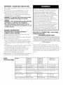
IMPORTANT - PLEASE READ AND FOLLOW
•Before beginning, please read these instructions completely
and carefully.
•Do not remove permanently affixed labels, warnings, or
plates from the product. This may void the warranty.
•Pleaseobserve all local ordinances. If local codes are
applicable, wire in accordance with the National Electrical
Code, ANSI/NFPA 70 - latest edition.
•WARNING - To reduce the riskof electric shock and fire,
do not use a flexible power-supply cord with this
appliance.
•WARNING - FOR OUTDOOR INSTALLATION, INSTALLER
MUST INSTALL A GROUND FAULT INTERRUPT.
•The installer should leave these instructions with the
consumer who should retain for local inspector's use and
for future reference.
GENERAL INFORMATION
•THIS UNIT IS NOT TO BEINSTALLED BELOW
CABINETS OR WALL MOUNTED.
•When installing this unit directly below other units, only
install with Viking built-in products
•Remove warming drawer carefully from carLon. Remove all
loose packaging and accessories.
*it is the responsibility of the installer to comply with local
codes. If no local codes are applicable, wire in accordance
with the National Electrical Code, ANSI/NFPA 70 - latest
edition.
•This appliance is not fused. Protect with a proper sizedfuse
or circuit breaker and a GFI for outdoor models.
•Line disconnect switch, circuit breaker, GFI (for outdoor
models) or plug/receptacle of power cord connection
should be readily accessible to the operator.
•Ground unit per applicable electrical codes.
*Any installation not matching the specifications discussed in
these instructions will void the manufacturer's warranty.
Make sure that incoming voltage is the same as
unit rating. An electric rating plate specifying
voltage, hertz, wattage, amps, and phase is
attached to the product. Wiring the warming
drawer with more voltage than it is rated for may
cause severe damage to the thermostat,
element, and other components. Wiring the
warming drawer with less voltage than it is rated
for may cause significant decrease in
performance. To reduce the risk of fire, electric
shock, or injury to persons, installation work and
electrical wiring must be clone by qualified
people in accordance with all applicable codes
and standards, including fire-rated conditions.
ELECTRICAL CONNECTION - USE COPPER
CONDUCTORS ONLY.
GROUNDING INSTRUCTIONS
This appliance must be connected to a grounded metal,
permanent wiring system, or an equipment-grounding
conductor must be run with the circuit conductors and
connected to the equipment-grounding terminal or lead
on the appliance.
With the appliance positioned in front of the cabinet
opening, connect wire leads extending from the power
supply to the terminal block of the unit. Make sure the
colored wires of the terminal block are connected to the
corresponding colored wires extending from the power
supply.
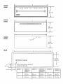
BASIC
SPECIFICATIONS
MODEL
Interior width
Interior height
Interior depth
Electrical
Recluirements
Max. Amp Usage
Approx. shipping Wt.
VEWD173
VEWD173T
DEWD171
DFWD171
17 1/4 (43.8 cm)
6" (15.2 cm)
22 3/4" (27.8 cm)
VEWD103
VEWD103T
DEWD101
DFWD101
20 1/2" (52.1 cm)
6" (15.2 cm)
22 3/4" (27.8 cm)
VEWD163
VEWD163T
25" (63.5 cm)
6" (15.2 cm)
22 3/4" (27.8 cm)
Hard wire direct with separate 15 amp minimum 2-wire with
ground circuit; 120 VAC/50-60 Hz
425 watts 450 watts 550 watts
3.6 amps 3.8 amps 4.6 amps
80 lb. (36 kg) 90 lb. (40.5 kg) 110 lb. (49.5 kg)

CABINET CUTOUT
INDOOR MODELS (VEWD, DEWD)
23 3/8"
(59.4cm)
I
I
9 I/4"
(23.5cm)
Cabinet
Model VEWD173 VEWD103 VEWD163
DEWD171 DEWD101
A 25 1/4" 28 1/4" 34"
(64.1 cm) (71.8 cm) (86.4 cm)
Mounting Screws
(4) - #8 x 3/4"
Cavity Assy.
Drawer
Assy.
OUTDOOR MODELS
Cabinet
(5.1 cm)
min.
23 3/8"
Model
A
91/4"
(23.5 cm)
Cavity Assy.
I all around
opening
silicon caulk that is
provided.
VEWD173T
25 1/4"
(64.1 cm)
VEWD103T
28 1/4"
(71.8 cm)
VEWD163T
34"
(86.4 cm)
Dra
Assy.

CABINET CUTOUT
DFWD MODELS
_L_ 24"
1
9s/8'q, /
[24.4 cm)'I-_I_
1
t
I
Cabinet
Model DFWD171 DFWD101
25 1/4" 28 1/4"
A (64.1 cm) (71.8 cm)
Mounting Screws
(4) - #8 x 3/4"
Cavity Assy.
insulation custom front
CUSTOM FRONT INSTALLATION - DFWD MODELS
• Open the drawer and remove the pan.
• Center the custom front and insulation around the inside panel.
•NOTE: Make sure the insulation provided is used between the custom panel and the inside door panel.
•Attach the custom front with the (6) six #8 x 3/4" screws provided.
CABINET INSTALLATION
*To remove drawer assembly, pull warming drawer pan out until fully extended. Slide finger along the right and left
side until you reach the black hand latches (located at the front of the rails). Pull up on both the right and left latches
and pull drawer pan support completely out.
*For outdoor models ONLY - Apply silicon caulk that is provided all around the back of the warming drawer trim.
*Slide cavity assembly into cabinet opening.
*Drill (4) pilot holes in cabinet using 1/8" drill bit. Permanently secure the warming drawer using the (4) #8 mounting
screws provided.
*Replace drawer assembly.

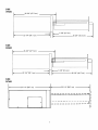
FRONT
VEWD
B
im • m m
}=
t
I0"
(25.4 cm)
FRONT
DEWD
B
I o
}=
10"
(25.4 cm)
FRONT
DFWD
B
3/4" thick
T
10 1/2"
(26.7 cm)
,L
REAR
C
120V Electrical opening
, (When facing cabinet, opening is
located on right side.)
[
8 31/32"
(22.8 cm)
MODEL VEWD172 DFWD171 VEWD102 DFWD101 VEWD162
VEWD172T VEWD102T VEWD162T
DEWD171 DEWD101
B 26 1/2" 26" 29 1/2" 29" 35 1/4"
(67.3 cm) (66.0 cm) (74.9 cm) (73.7 cm) (89.5 cm)
C 24 7/8" 24 7/8" 27 7/8" 27 7/8" 33 5/8"
(63.2 cm) (63.2 cm) (70.8 cm) (70.8 cm) (85.4 cm)
5

SIDE
VEWD
26 3/4" (67.9 cm)
23 1/4" (59.1 cm)
1 3/8" (3.5 cm)
,_ 25 3/4" (65.4 cm)
SIDE
DEWD
26 3/4" (67.9 cm)
23 1/4" (59.1 cm)
_1 3/8" (3.5 cm)
26 1/4" (66.7 cm)
SIDE
DFWD
23 1/4" (58.7 cm)
/
: 23 1/4" (58.7 cm) _,J
h
..............?i

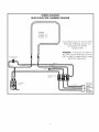
WIRING DIAGRAM
BUILT-IN ELECTRIC WARMING DRAWER
INDICATOR LIGHT
PE050024
RED 6" RED 10"
BLACK 15"
ELEMENT
PJ010008- 36"
PJ010009- 30"
PJ010010- 27"
r
GROUND
lu
WHITE 15"
WHITE 10"
GREEN/YELLOW B"
FOR CONNECTION TO THE FACTORY
INSTALLED TERMINAL BLOCK, USE
ALUMINUM OR COPPER
CONDUCTORS
WARNING: TO REDUCE THE RISK OF
ELECTRIC SHOCK AND FIRE, DO NOT
USE A FLEXIBLE POWER-SUPPLY CORD
WITH THIS APPLIANCE.
TERMINAL BLOCK
PE070147
THERMOSTAT
PB10167
NEUTRAL
POWER SUPPLY
CONNECTIONS
ER
O, ¢_UTOOOR
INSTALLER
MUST SUPPLY
GFC INTERRUPT

__iiiiii_ o
V_kmg Range Corporation
111 Front Street
Greenwood, M_sslssFppr38930 USA
(662) 455-1200
For more product mformat_on,
call 1-888-VIKING1 (845-4641) or
ws_tthe V_k_ngweb stte
www wkmgrange.com
F1615L (PSO206VR)
-
 1
1
-
 2
2
-
 3
3
-
 4
4
-
 5
5
-
 6
6
-
 7
7
-
 8
8


Viking Professional VEWD103T Installation guide
- Type
- Installation guide
Ask a question and I''ll find the answer in the document
Finding information in a document is now easier with AI
Other documents
-
Viking DFWD171 Installation guide
-
Viking Range VEWD163 Installation guide
-
-
-
-
-
-
Kawasaki MULE 4010 DIESEL 4X4 - 2011 User manual
-
Viking VEWDO530 Installation guide
-