Page is loading ...

IMPORTANT
READ AND UNDERSTAND INSTRUCTIONS BEFORE INSTALLING OR USING HEATER.
RETAIN INSTRUCTIONS FOR FUTURE REFERENCE. CHECK LOCAL CODES AND ORDINANCES FOR PERMITTED USE.
MODEL FR-700F
CONTENTS
SECTION A:
Specifications ····························································· 2
SECTION B:
Safety Tips for Operation ············································ 3
SECTION C:
Fuel Guide ··································································· 4
SECTION D:
Operation ···································································· 5
SECTION E:
Error Messages ························································ 10
SECTION F:
Installation ································································ 11
SECTION G:
Fuel Storage and Supply System ······························ 23
VENTED HEATING SYSTEM
INSTALLATION AND OPERATION INSTRUCTIONS

1
SECTION B:
SAFETY TIPS FOR OPERATION
CAUTION: Heater and vent pipe system must be properly installed before operation. Please follow
instructions under “Installation”, Section F.
1. Never use any fuel other than Kerosene. NEVER USE GASOLINE. Use of gasoline
can lead to uncontrollable flames, resulting in destructive fire.
2. Due to high surface temperatures, keep heater away from children, furniture and
clothing while in operation (See Page 12).
3. To prevent abnormal operation and prolong heater life, be sure to perform routine
maintenance (See Pages 9).
4. Never store or transport fuel in other than a metal or plastic container that is (1)
acceptable for fuel and (2) clearly marked “KEROSENE”. Never store fuel in the
living space.
RIGHT WRONG
GAS
KEROSENE
Kero-
sene
Danger
SECTION A:
SPECIFICATIONS
Model: FR-700F
Heater Efficiency: 92.4% (1)
Heat Rating: High - 7.00 kW (23,900 BTU/h)
Low - 1.75 kW ( 5,980 BTU/h)
Fuel Consumption: High - 0.791 L/h
Low - 0.198 L/h
Fuel system: External tank (2)
Fuel Type: Kerosene only
Dimensions (W × H × D): 700 × 593 × 422 mm
Weight: 28 kg
Vent Pipe Hole: 70 ~ 80 mm diameter
Maximum Length of Vent Pipe System: 3 m, 3 bents or less
Electrical Rating: 220 Volts AC, 50 Hz
Preheat - 260 W
Burning - 45 W
(1) Heat and vaporized water are produced by the combustion process of this heater. This rating does not take into
account heat loss due to condensation of water vapor.
(2) External tank to be purchased from local suppliers.

2
SECTION B:
SAFETY TIPS FOR OPERATION
CAUTION: Heater and vent pipe system must be properly installed before operation. Please follow
instructions under “Installation”, Section F.
1. Never use any fuel other than Kerosene. NEVER USE GASOLINE. Use of gasoline
can lead to uncontrollable flames, resulting in destructive fire.
2. Due to high surface temperatures, keep heater away from children, furniture and
clothing while in operation (See Page 12).
3. To prevent abnormal operation and prolong heater life, be sure to perform routine
maintenance (See Pages 9).
4. Never store or transport fuel in other than a metal or plastic container that is (1)
acceptable for fuel and (2) clearly marked “KEROSENE”. Never store fuel in the
living space.
RIGHT WRONG
GAS
KEROSENE
Kero-
sene
Danger
SECTION A:
SPECIFICATIONS
Model: FR-700F
Heater Efficiency: 92.4% (1)
Heat Rating: High - 7.00 kW (23,900 BTU/h)
Low - 1.75 kW ( 5,980 BTU/h)
Fuel Consumption: High - 0.791 L/h
Low - 0.198 L/h
Fuel system: External tank (2)
Fuel Type: Kerosene only
Dimensions (W × H × D): 700 × 593 × 422 mm
Weight: 28 kg
Vent Pipe Hole: 70 ~ 80 mm diameter
Maximum Length of Vent Pipe System: 3 m, 3 bents or less
Electrical Rating: 220 Volts AC, 50 Hz
Preheat - 260 W
Burning - 45 W
(1) Heat and vaporized water are produced by the combustion process of this heater. This rating does not take into
account heat loss due to condensation of water vapor.
(2) External tank to be purchased from local suppliers.

3
1. Introduction
The heater is an easy to use vented petroleum heater. It
provides considerable quantities of heat, automatically
regulates the room temperature, uses very little fuel and
electricity and has options for automatic or manual
operation.
This section provides all the information required for the
operation of the Vented heating system. All specified
operating procedures must be carried out in the order in
which they are described.
SECTION D:
OPERATION
SECTION C:
FUEL GUIDE
The FF-70AQ is designed for use with Kerosene. Use of low-quality fuel will cause burner performance to drop,
leading to abnormal combustion and reduced heater life.
Purchase only Kerosene, in non-red cans reserved exclusively for fuel and marked accordingly with the word
“KEROSENE”. Always store your fuel in a separate area from where you store gasoline for your power equipment to
avoid accidental use of gasoline in your heater.
What to Buy . . .
ALWAYS: Clean and high-quality Kerosene.
ALWAYS: Fuel free of contaminants, water or cloudiness.
NEVER: Gasoline, alcohol, white gas, camp stove fuel or additives.
NEVER: Yellow or sour-smelling fuel.
How to Use It . . . (when optional removable fuel tank is used)
ALWAYS: Fill heater away from living quarters when heater is cool; use
siphon.
ALWAYS: Watch fuel gauge to avoid overfilling heater.
How to Store It . . .
ALWAYS: Store in a clean container, clearly marked KEROSENE.
ALWAYS:
Store away from direct sunlight, heat sources or extreme temperature
changes.
NEVER: In a glass container, or one that has been used for other fuels.
NEVER: For longer than six months. Begin each heating season with fresh
fuel; discard at the end of season.
NEVER: In the living space.
Why It is Important . . .
Pure, clean fuel is essential for safe and efficient heater operation. Poor quality or
contaminated fuel can cause:
● Excess tar deposits on burner and flue pipe
● Incomplete combustion
● Reduced heater life
Use of a highly volatile flammable fuel such as gasoline can produce uncontrol-
lable flames, creating a severe fire hazard.

4
1. Introduction
The heater is an easy to use vented petroleum heater. It
provides considerable quantities of heat, automatically
regulates the room temperature, uses very little fuel and
electricity and has options for automatic or manual
operation.
This section provides all the information required for the
operation of the Vented heating system. All specified
operating procedures must be carried out in the order in
which they are described.
SECTION D:
OPERATION
SECTION C:
FUEL GUIDE
The FF-70AQ is designed for use with Kerosene. Use of low-quality fuel will cause burner performance to drop,
leading to abnormal combustion and reduced heater life.
Purchase only Kerosene, in non-red cans reserved exclusively for fuel and marked accordingly with the word
“KEROSENE”. Always store your fuel in a separate area from where you store gasoline for your power equipment to
avoid accidental use of gasoline in your heater.
What to Buy . . .
ALWAYS: Clean and high-quality Kerosene.
ALWAYS: Fuel free of contaminants, water or cloudiness.
NEVER: Gasoline, alcohol, white gas, camp stove fuel or additives.
NEVER: Yellow or sour-smelling fuel.
How to Use It . . . (when optional removable fuel tank is used)
ALWAYS: Fill heater away from living quarters when heater is cool; use
siphon.
ALWAYS: Watch fuel gauge to avoid overfilling heater.
How to Store It . . .
ALWAYS: Store in a clean container, clearly marked KEROSENE.
ALWAYS:
Store away from direct sunlight, heat sources or extreme temperature
changes.
NEVER: In a glass container, or one that has been used for other fuels.
NEVER: For longer than six months. Begin each heating season with fresh
fuel; discard at the end of season.
NEVER: In the living space.
Why It is Important . . .
Pure, clean fuel is essential for safe and efficient heater operation. Poor quality or
contaminated fuel can cause:
● Excess tar deposits on burner and flue pipe
● Incomplete combustion
● Reduced heater life
Use of a highly volatile flammable fuel such as gasoline can produce uncontrol-
lable flames, creating a severe fire hazard.

5
Reset Button
3. Prior to use
Step 1: Open the Valve(s)
Open the valve(s) of the external fuel tank.
Step 2: Start the Fuel flow
If using heater for the first
time, or after heater has
been out of fuel, press the
red reset button once for a
period of one second in
order to send fuel to the fuel
sump.
Note: Make sure there is no fuel leakage from the
fuel line or joints.
Also make sure fuel tank is not too high. See
installation instructions.
Step 3: Set the top guard
The top guard is in the
carton box. Please take it
out from the box, and set it
on the top plate of the heater
before using it to prevent a
fire.
Step 4: Plug in the heater
Insert the plug into the wall-socket (220 Volts –
AC/50Hz).
Step 5: Setting the clock
Important: The clock on the heater must always be
set to the correct time.
It is only possible to set the correct time, when the heater
is connected to the mains and not burning.
Use the adjustment buttons to set the time.
First press either of the two buttons to switch on the
function "empty full"(the CLOCK light and the information
display will start blinking). Next, set the hours using the
button on the left (-HOUR) and the minutes using the
button on the right (+MIN.). Press once to increase the
value by one step. When you hold down the button, the
value will continue going up, until you release the button
again. After approximately 10 seconds the blinking will
stop and the setting will be locked. After switching off the
heater, the clock time will be displayed.
Fig. D-1 Operation panel
1. ON/OFF button:
The main switch to turn the heater on and off. Switch
it “ON” to activate the heater. Combustion will start
after a 2-6 minutes pre-heating period. The heater has
4 settings “HIGH”, “MEDIUM”, “LOW” and “OFF”.
2. Adjustment buttons:
Temperature selection switches offer the user the option
to select the desired temperature during operation.
3. Information display:
Displays the clock, set temperature, room temperature
and error codes.
4. Heat adjusting slide knob
Manual operation …
Slide the heat adjusting slide knob to right-side to
select your desired heat yield from “LOW” to “HIGH”.
Automatic operation …
Set the heat adjusting slide knob to left-side “Auto”
position to set the Automatic operation. The heater
will operate automatically in accordance with the set
and room temperature.
2. Operating elements and lights
5. SAVE button:
Allows you to limit the temperature. When this function
is activated, the heater will automatically switch off
and on again.
6. TIMER button:
Allows you to switch on the heater automatically at a
preset time.
7. CHILDPROOF LOCK button:
Can be used to prevent children accidentally changing
the heater settings.
8. Filter button:
This button is for releasing the filter lamp.
To release the filter lamp
When the filter lamp is on, please clean the fan filter
(See pages 10). After cleaning, please keep pressing
the filter button for more than 3 seconds. Then the
filter lamp will be off.
1. ON/OFF button
2. Adjustment buttons
4. Information display
3. Heat adjusting slide knob5. Save button8. Filter button7. Childproof button 6. Timer button

6
Reset Button
3. Prior to use
Step 1: Open the Valve(s)
Open the valve(s) of the external fuel tank.
Step 2: Start the Fuel flow
If using heater for the first
time, or after heater has
been out of fuel, press the
red reset button once for a
period of one second in
order to send fuel to the fuel
sump.
Note: Make sure there is no fuel leakage from the
fuel line or joints.
Also make sure fuel tank is not too high. See
installation instructions.
Step 3: Set the top guard
The top guard is in the
carton box. Please take it
out from the box, and set it
on the top plate of the heater
before using it to prevent a
fire.
Step 4: Plug in the heater
Insert the plug into the wall-socket (220 Volts –
AC/50Hz).
Step 5: Setting the clock
Important: The clock on the heater must always be
set to the correct time.
It is only possible to set the correct time, when the heater
is connected to the mains and not burning.
Use the adjustment buttons to set the time.
First press either of the two buttons to switch on the
function "empty full"(the CLOCK light and the information
display will start blinking). Next, set the hours using the
button on the left (-HOUR) and the minutes using the
button on the right (+MIN.). Press once to increase the
value by one step. When you hold down the button, the
value will continue going up, until you release the button
again. After approximately 10 seconds the blinking will
stop and the setting will be locked. After switching off the
heater, the clock time will be displayed.
Fig. D-1 Operation panel
1. ON/OFF button:
The main switch to turn the heater on and off. Switch
it “ON” to activate the heater. Combustion will start
after a 2-6 minutes pre-heating period. The heater has
4 settings “HIGH”, “MEDIUM”, “LOW” and “OFF”.
2. Adjustment buttons:
Temperature selection switches offer the user the option
to select the desired temperature during operation.
3. Information display:
Displays the clock, set temperature, room temperature
and error codes.
4. Heat adjusting slide knob
Manual operation …
Slide the heat adjusting slide knob to right-side to
select your desired heat yield from “LOW” to “HIGH”.
Automatic operation …
Set the heat adjusting slide knob to left-side “Auto”
position to set the Automatic operation. The heater
will operate automatically in accordance with the set
and room temperature.
2. Operating elements and lights
5. SAVE button:
Allows you to limit the temperature. When this function
is activated, the heater will automatically switch off
and on again.
6. TIMER button:
Allows you to switch on the heater automatically at a
preset time.
7. CHILDPROOF LOCK button:
Can be used to prevent children accidentally changing
the heater settings.
8. Filter button:
This button is for releasing the filter lamp.
To release the filter lamp
When the filter lamp is on, please clean the fan filter
(See pages 10). After cleaning, please keep pressing
the filter button for more than 3 seconds. Then the
filter lamp will be off.
1. ON/OFF button
2. Adjustment buttons
4. Information display
3. Heat adjusting slide knob5. Save button8. Filter button7. Childproof button 6. Timer button

7
☞
☞
5. Timer operation
The timer allows you to switch on the heater automati-
cally at a preset time.
In order to switch on the timer, the correct time must
have been set and the heater should be off. Follow the
procedure below:
[1] Press the TIMER button. The TIMER light and the
information display will start blinking.
[2] Use the adjustment buttons to set the time at which
the heater must ignite. Use the button on the left
(-HOUR) to set the hours and the button on the right
(+MIN.) to set the minutes (interval of 10 minutes).
[3] Press the ON/OFF button while the information
display is blinking.
[4] After approximately 10 seconds the information
display will show CLOCK again and the TIMER
indicator light will light up, indicating that the timer
function has been activated.To clear the timer
setting, press the ON/OFF button once.
Note: When the room temperature is less
than15˚C, the preset time is changed
automatically depending on the room
temperature in orderto heat the room by the
desired time.
6. Room temperature sensor
The room temperature sensor is fitted with a 2.5 meter
cable. This is located on the back of the heater. Ensure
that the cable does not touch the outlet tube. The room
temperature sensor can be installed with cellotape or
with a wood screw.
Select the location where the sensor is to be installed
insuch a way that it will not be exposed to direct
sunlight, draughts or the warm air flowing out of the
heater.
7. Childproof lock
The childproof lock can be used to prevent children
accidentally changing the heater settings. When the
heater is burning and the childproof lock is on, the
heater can only be switched off. Other functions are
blocked then. If the heater has already been switched
off, the childproof lock also prevents accidental ignition
of the heater. Activate the childproof lock by pressing
the appropriate button and holding it down for more
than 3 seconds. The CHILD LOCK indicator light will
lightup, indicating that the childproof lock has been
activated. Switch off the childproof lock by pressing the
button and holding it down for more than 3 seconds
once again.
8. Switching off the heater
There are two ways to switch off the heater.
[1]
Press the ON/OFF button. The information display will
show the CLOCK signal. The air circulation ventilator
and the ventilator motor continue to operate for
approximately 3 minutes in order to cool the heater
down.
[2] Press the TIMER button, when you want to switch off
the heater and ignite it again with the timer the next
time. This not only switches off the heater, but it also
activates the timer function. You can change the
required time with the adjustment buttons.
9. Recovery after overheating
The heater is protected against damage caused by
overheating.
A sensor will activate if the temperature in the housing
exceeds 90˚C.
Step 1: Switch the heater OFF.
Step 2: Allow the heater to cool down.
Ensure that the metal housing has cooled
sufficiently before touching it.
Under normal conditions, a period of 30 to 45 minutes
is sufcompletely.
Step 3: Pull the heater plug out of the socket.
☞☞
☞
4. Igniting the heater
The heater is operated directly by the user. You can
choose the heat yield is controlled automatically in
accordance with the room temperature registered by the
temperature sensor or selected manually by setting the
heat adjusting slide knob.
Step 1: Switch the heater ON
Press the ON/OFF button. The current room temperature
is displayed on the information display when the heater
is in the manual operation. However the set temperature
is also displayed when you choose the automatic
operation. The ON/OFF light starts to flash, after which
the heater will switch on.
Note: (*) The start-up time depends on the
room temperature.
After 8-12 minutes, the heater will automatically select
the correct operating mode and the ON/OFF button will
now be illuminated continuously.
Room temperature:
under 0˚C 12 minutes
0˚C - 15˚C 10 minutes
15˚C 8 minutes
If no flames are visible after the start-up period, the
heater will deactivate and then restart automatically. If
flames are still not detected, the heater will deactivate
and will have to be restarted manually (error code E-2
on the information display).
Step 2: Setting the room temperature
Set the heat adjusting slide knob to left-side “Auto”
position. The temperature setting can only be adjusted,
when the heater is burning. Use the adjustment
buttons to adjust the temperature. First press either of
the two buttons to switch on the function (the TEMP
light next to the information display will start blinking).
Next, adjust the temperature using the button on the
right (+MIN.) to set the temperature to a higher setting
and the button on the left (-HOUR) to lower the
temperature. Press once to increase the value one
step. After approximately 10 seconds the light will stop
blinking and setting will belocked. The available
temperature settings range from10˚C minimum to 32˚C
maximum. When the heater has been unplugged (or
after a power failure), the temperature will reset to the
factory setting of 20˚C.The operating mode is
automatically controlled in accordance with the room
temperature detected by the room temperature sensor.
The heater works in the “HIGH” operating mode until
the room temperature has reached the desired level.
When the room temperature reaches the chosen
setting the heater automatically switches to the “MED”
or “LOW” operating mode in order to maintain the
desired temperature.
Step 3: The correct use of ‘SAVE’
The ‘SAVE’ function allows you to limit the temperature.
When this function is activated, the heater will
automatically switch off, when the room temperature
exceeds theset temperature by 2˚C. Subsequently, when
the roomtemperature has dropped again to the set
temperature,the heater will automatically switch on
again. Activatethe ‘SAVE’ setting by pressing the
appropriate button.The SAVE indicator light will light up.
Switch off thefunction by pressing the SAVE button once
again.
Without the ‘SAVE’ setting your heater will
maintain the set temperature by approxima-
tion as well, by adjusting its heating capacity.
‘SAVE’ is an economy setting, which you can
use when, for in stance, you are not present
in the room or to keep it frost-free.
Step 4: Setting the heat yield (Manual operation)
Adjust your desired combustion mode by setting the
heat adjusting slide knob between “LOW” and “HIGH”.
The combustion will keep the selected position.
The first 8-12 minutes from switched ON the
heater, the heater will keep “Min.” combus-
tion mode for the pre-combustion.
After that, the combustion will change
automatically to selected position.
You cannot change the heat yield first 8-12
minutes.

8
☞
☞
5. Timer operation
The timer allows you to switch on the heater automati-
cally at a preset time.
In order to switch on the timer, the correct time must
have been set and the heater should be off. Follow the
procedure below:
[1] Press the TIMER button. The TIMER light and the
information display will start blinking.
[2] Use the adjustment buttons to set the time at which
the heater must ignite. Use the button on the left
(-HOUR) to set the hours and the button on the right
(+MIN.) to set the minutes (interval of 10 minutes).
[3] Press the ON/OFF button while the information
display is blinking.
[4] After approximately 10 seconds the information
display will show CLOCK again and the TIMER
indicator light will light up, indicating that the timer
function has been activated.To clear the timer
setting, press the ON/OFF button once.
Note: When the room temperature is less
than15˚C, the preset time is changed
automatically depending on the room
temperature in orderto heat the room by the
desired time.
6. Room temperature sensor
The room temperature sensor is fitted with a 2.5 meter
cable. This is located on the back of the heater. Ensure
that the cable does not touch the outlet tube. The room
temperature sensor can be installed with cellotape or
with a wood screw.
Select the location where the sensor is to be installed
insuch a way that it will not be exposed to direct
sunlight, draughts or the warm air flowing out of the
heater.
7. Childproof lock
The childproof lock can be used to prevent children
accidentally changing the heater settings. When the
heater is burning and the childproof lock is on, the
heater can only be switched off. Other functions are
blocked then. If the heater has already been switched
off, the childproof lock also prevents accidental ignition
of the heater. Activate the childproof lock by pressing
the appropriate button and holding it down for more
than 3 seconds. The CHILD LOCK indicator light will
lightup, indicating that the childproof lock has been
activated. Switch off the childproof lock by pressing the
button and holding it down for more than 3 seconds
once again.
8. Switching off the heater
There are two ways to switch off the heater.
[1]
Press the ON/OFF button. The information display will
show the CLOCK signal. The air circulation ventilator
and the ventilator motor continue to operate for
approximately 3 minutes in order to cool the heater
down.
[2] Press the TIMER button, when you want to switch off
the heater and ignite it again with the timer the next
time. This not only switches off the heater, but it also
activates the timer function. You can change the
required time with the adjustment buttons.
9. Recovery after overheating
The heater is protected against damage caused by
overheating.
A sensor will activate if the temperature in the housing
exceeds 90˚C.
Step 1: Switch the heater OFF.
Step 2: Allow the heater to cool down.
Ensure that the metal housing has cooled
sufficiently before touching it.
Under normal conditions, a period of 30 to 45 minutes
is sufcompletely.
Step 3: Pull the heater plug out of the socket.
☞☞
☞
4. Igniting the heater
The heater is operated directly by the user. You can
choose the heat yield is controlled automatically in
accordance with the room temperature registered by the
temperature sensor or selected manually by setting the
heat adjusting slide knob.
Step 1: Switch the heater ON
Press the ON/OFF button. The current room temperature
is displayed on the information display when the heater
is in the manual operation. However the set temperature
is also displayed when you choose the automatic
operation. The ON/OFF light starts to flash, after which
the heater will switch on.
Note: (*) The start-up time depends on the
room temperature.
After 8-12 minutes, the heater will automatically select
the correct operating mode and the ON/OFF button will
now be illuminated continuously.
Room temperature:
under 0˚C 12 minutes
0˚C - 15˚C 10 minutes
15˚C 8 minutes
If no flames are visible after the start-up period, the
heater will deactivate and then restart automatically. If
flames are still not detected, the heater will deactivate
and will have to be restarted manually (error code E-2
on the information display).
Step 2: Setting the room temperature
Set the heat adjusting slide knob to left-side “Auto”
position. The temperature setting can only be adjusted,
when the heater is burning. Use the adjustment
buttons to adjust the temperature. First press either of
the two buttons to switch on the function (the TEMP
light next to the information display will start blinking).
Next, adjust the temperature using the button on the
right (+MIN.) to set the temperature to a higher setting
and the button on the left (-HOUR) to lower the
temperature. Press once to increase the value one
step. After approximately 10 seconds the light will stop
blinking and setting will belocked. The available
temperature settings range from10˚C minimum to 32˚C
maximum. When the heater has been unplugged (or
after a power failure), the temperature will reset to the
factory setting of 20˚C.The operating mode is
automatically controlled in accordance with the room
temperature detected by the room temperature sensor.
The heater works in the “HIGH” operating mode until
the room temperature has reached the desired level.
When the room temperature reaches the chosen
setting the heater automatically switches to the “MED”
or “LOW” operating mode in order to maintain the
desired temperature.
Step 3: The correct use of ‘SAVE’
The ‘SAVE’ function allows you to limit the temperature.
When this function is activated, the heater will
automatically switch off, when the room temperature
exceeds theset temperature by 2˚C. Subsequently, when
the roomtemperature has dropped again to the set
temperature,the heater will automatically switch on
again. Activatethe ‘SAVE’ setting by pressing the
appropriate button.The SAVE indicator light will light up.
Switch off thefunction by pressing the SAVE button once
again.
Without the ‘SAVE’ setting your heater will
maintain the set temperature by approxima-
tion as well, by adjusting its heating capacity.
‘SAVE’ is an economy setting, which you can
use when, for in stance, you are not present
in the room or to keep it frost-free.
Step 4: Setting the heat yield (Manual operation)
Adjust your desired combustion mode by setting the
heat adjusting slide knob between “LOW” and “HIGH”.
The combustion will keep the selected position.
The first 8-12 minutes from switched ON the
heater, the heater will keep “Min.” combus-
tion mode for the pre-combustion.
After that, the combustion will change
automatically to selected position.
You cannot change the heat yield first 8-12
minutes.

9
ERROR CODE
E-0
E-2
E-6
E-8
E-12
E-13
E-22
E-23
-- : --
Hi
Lo
INFORMATION
Power interrupted.
Ignition safety feature is activated.
Extinguished during operation.
Blower motor malfunction.
Overheating safety feature is activated.
Burner thermistor malfunction
Excess fuel in the burner
Ignition failure three times
Primary flame (Flame sensor) is malfunction and / or dirty.
Timer is not setting.
Room temperature is higher than 35˚C.
Position of room temperature sensor is not correct.
Room temperature is lower than -10˚C.
Room thermistor malfunction or disconnected.
WHAT TO DO
Re-ignite the heater
Contact your dealer
Contact your dealer
Contact your dealer
Clean the air filter and remove dust.
Contact your dealer
Contact your dealer
Contact your dealer
Contact your dealer.
Set the timer.
Check the position of room temperature
sensor.
Check the position of room temperature
sensor.
SECTION E:
ERROR MESSAGE
☞☞☞
☞
Step 4: Look for the source of the overheating.
Overheating is usually caused by objects that
obstruct the free flow of air. Check that the
circulation ventilator or exhaust pipes are not
blocked. Check that there are no objects
blocking the outlet system.
Step 5: Remove the front panel.
Step 6: Clean the inside of the heater.
Before starting to clean the heater, ensure
that the interior is cool enough to touch.
Wipe alldust off the outside of the housing
with a clean,non-fluffy, damp cloth or another
suitable cleaning aid. Do not forget to clean
the out side of the heat chamber and the heat
exchanger.
Step 7: Re-attach the front panel.
Step 8: Insert the heater plug into the socket.
Step 9: Switch the heater ON.
Step 10: Re-program the heater (clock and timer).
If the heater overheats after the completion of
a recovery procedure, contact your dealer
and do not switch the heater on until the
problem has been resolved.
10. Cleaning the filter (monthly)
Switch off the heater and let it cool down, before you
start any maintenance work. Also disconnect the plug
from the mains.
Your needs hardly any maintenance. It is, however,
important that you clean the louvers, grilles and
circulation fancover on the back of the heater weekly.
Periodically checkthe flue pipe connection for leakage or
separation.
We recommend that you remove dust and stains in time
with a damp cloth, because otherwise these may cause
stains that are hard to remove.
Do not remove any heater components
yourself. Always contact your dealer for
repairs. Whenthe power cord is damaged, it
may only bereplaced by an authorized fitter.
Use a new cordof the type H05 VV-F.
11. Before consulting an expert
The following situations do not indicate defects.
While switching the heater on or off.
White smoke can be seen when the heater is switched
on for the first time.
Machine oil or dust on the burner chamber or heat
exchanger is burning.
The flames flicker for several minutes after the heater
has been ignited.
The ignition rod continues to function when the heater is
cold, even several minutes after ignition. This may cause
the flames to be a little larger.
The heater makes intermittent creaking sounds when
warming up or cooling down.
Expansion and shrinkage of metal parts may cause a
slight creaking sound.
Circulation of air in the room does not start immediately
when the heater is lit.
To prevent unpleasant cold draughts, the ventilator only
switches on when the heater has become warm.
A loud clicking sound can be heard during the first use
or when the fuel runs out.
There is air in the fuel pump. This should be gone within
approximately 1 minute.
Note: The fuel pump may make a slight
ticking sound during normal operation. This
does not indicate a problem.
While the heater is in operation
A part of the burner pot and/or heat exchanger becomes
red in color during operation. This is normal and does
not indicate a problem.

10
ERROR CODE
E-0
E-2
E-6
E-8
E-12
E-13
E-22
E-23
-- : --
Hi
Lo
INFORMATION
Power interrupted.
Ignition safety feature is activated.
Extinguished during operation.
Blower motor malfunction.
Overheating safety feature is activated.
Burner thermistor malfunction
Excess fuel in the burner
Ignition failure three times
Primary flame (Flame sensor) is malfunction and / or dirty.
Timer is not setting.
Room temperature is higher than 35˚C.
Position of room temperature sensor is not correct.
Room temperature is lower than -10˚C.
Room thermistor malfunction or disconnected.
WHAT TO DO
Re-ignite the heater
Contact your dealer
Contact your dealer
Contact your dealer
Clean the air filter and remove dust.
Contact your dealer
Contact your dealer
Contact your dealer
Contact your dealer.
Set the timer.
Check the position of room temperature
sensor.
Check the position of room temperature
sensor.
SECTION E:
ERROR MESSAGE
☞☞☞
☞
Step 4: Look for the source of the overheating.
Overheating is usually caused by objects that
obstruct the free flow of air. Check that the
circulation ventilator or exhaust pipes are not
blocked. Check that there are no objects
blocking the outlet system.
Step 5: Remove the front panel.
Step 6: Clean the inside of the heater.
Before starting to clean the heater, ensure
that the interior is cool enough to touch.
Wipe alldust off the outside of the housing
with a clean,non-fluffy, damp cloth or another
suitable cleaning aid. Do not forget to clean
the out side of the heat chamber and the heat
exchanger.
Step 7: Re-attach the front panel.
Step 8: Insert the heater plug into the socket.
Step 9: Switch the heater ON.
Step 10: Re-program the heater (clock and timer).
If the heater overheats after the completion of
a recovery procedure, contact your dealer
and do not switch the heater on until the
problem has been resolved.
10. Cleaning the filter (monthly)
Switch off the heater and let it cool down, before you
start any maintenance work. Also disconnect the plug
from the mains.
Your needs hardly any maintenance. It is, however,
important that you clean the louvers, grilles and
circulation fancover on the back of the heater weekly.
Periodically checkthe flue pipe connection for leakage or
separation.
We recommend that you remove dust and stains in time
with a damp cloth, because otherwise these may cause
stains that are hard to remove.
Do not remove any heater components
yourself. Always contact your dealer for
repairs. Whenthe power cord is damaged, it
may only bereplaced by an authorized fitter.
Use a new cordof the type H05 VV-F.
11. Before consulting an expert
The following situations do not indicate defects.
While switching the heater on or off.
White smoke can be seen when the heater is switched
on for the first time.
Machine oil or dust on the burner chamber or heat
exchanger is burning.
The flames flicker for several minutes after the heater
has been ignited.
The ignition rod continues to function when the heater is
cold, even several minutes after ignition. This may cause
the flames to be a little larger.
The heater makes intermittent creaking sounds when
warming up or cooling down.
Expansion and shrinkage of metal parts may cause a
slight creaking sound.
Circulation of air in the room does not start immediately
when the heater is lit.
To prevent unpleasant cold draughts, the ventilator only
switches on when the heater has become warm.
A loud clicking sound can be heard during the first use
or when the fuel runs out.
There is air in the fuel pump. This should be gone within
approximately 1 minute.
Note: The fuel pump may make a slight
ticking sound during normal operation. This
does not indicate a problem.
While the heater is in operation
A part of the burner pot and/or heat exchanger becomes
red in color during operation. This is normal and does
not indicate a problem.

11
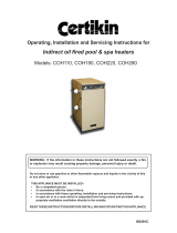
Fig. 1: Gaps heater/exhaust pipe
FR-700F
☞
☞
4. Wiring for the room temperature sensor
A temperature sensor that can be fitted to a wall
measures the room temperature in order to
automatically regulate the heating. The standard
sensor wire is approximately 2.5 m long.
The sensor may not be placed in a draught,
direct sunlight or the warm air flowing out of
the heater. This may cause incorrect
temperature indications.
5. Unpacking
Save all packaging materials for possible future
transportation.
A) Remove the cardboard (drilling) template and the
user’s manual from the packaging.
B) Remove the drip tray from the packaging.
C) Remove the box with the installation kit from the
packaging.
D) Remove the heater from the packaging.
E) Remove the plastic bag containing the parts.
F) Remove the exhaust pipe from the bottom of the
box.
G) Check that all parts are present.
Only the standard feed and exhaust system
is supplied with the heater.
More than 30 cm
More than 10 cm
More than 1.5 m
More than 60 cm
More than 30 cm
☞
☞
1. Introduction
This section contains all the relevant information,
specifically:
• Installation specifications
• List of installation tools
•
Instructions for the installation of the Vented Heating System
The heater can be installed at any location, on condition
that there is full compliance with electrical, fuel and
emission regulations.
Before you start installing the heating system (including
electrical wiring), check the local building and fire safety
regulations. The requirements stipulated in these
regulations must be respected in order to guarantee a
legally approved installation and correct operation.
The heater was designed to be used to a
maximum altitude of 1000m above sea level.
Contact your dealer for the necessary
adjustments if you wish to use it at a higher
altitude.
2. Moving the heater
In addition to the space required for the heater, extra
room must be kept free for air circulation. The Vented
Heating System can be placed on any type of flooring
and operate safely, unless fuel or fire safety regulations
specify otherwise. Check the gaps in the manner
stipulated in the instructions in the manual.
Recommended tool kit
1. Crosshead screwdriver
2. Steel tape measure
3. Felt-tip pen or pencil
4. Cement for exterior use
5.
Electric drill (clockwise and anti-clockwise recommended)
6. Hole cutting saw, jig saw or other tools suitable for
sawing a hole of 70~80 mm for the exhaust pipe
7. Long drill
8. Standard screwdrivers
9. Volt, Ohmmeter
10. Spirit level
11. Small range of self-tapping screws
12. Insulated screwdriver
13. Protective material for your floor
14. Container for fuel exhaust pipe
3. The electrical supply system
The electrical system must be protected from overloads
by an at least 5-Ampere fuse or contact breaker.
Some installations (such as for use in mobile
homes) must be fitted with a permanent
connection to the household power circuits.
This must be done by a recognised
electrician.
SECTION F:
INSTALLATION

12
Fig. 1: Gaps heater/exhaust pipe
FR-700F
☞
☞
4. Wiring for the room temperature sensor
A temperature sensor that can be fitted to a wall
measures the room temperature in order to
automatically regulate the heating. The standard
sensor wire is approximately 2.5 m long.
The sensor may not be placed in a draught,
direct sunlight or the warm air flowing out of
the heater. This may cause incorrect
temperature indications.
5. Unpacking
Save all packaging materials for possible future
transportation.
A) Remove the cardboard (drilling) template and the
user’s manual from the packaging.
B) Remove the drip tray from the packaging.
C) Remove the box with the installation kit from the
packaging.
D) Remove the heater from the packaging.
E) Remove the plastic bag containing the parts.
F) Remove the exhaust pipe from the bottom of the
box.
G) Check that all parts are present.
Only the standard feed and exhaust system
is supplied with the heater.
More than 30 cm
More than 10 cm
More than 1.5 m
More than 60 cm
More than 30 cm
☞
☞
1. Introduction
This section contains all the relevant information,
specifically:
• Installation specifications
• List of installation tools
•
Instructions for the installation of the Vented Heating System
The heater can be installed at any location, on condition
that there is full compliance with electrical, fuel and
emission regulations.
Before you start installing the heating system (including
electrical wiring), check the local building and fire safety
regulations. The requirements stipulated in these
regulations must be respected in order to guarantee a
legally approved installation and correct operation.
The heater was designed to be used to a
maximum altitude of 1000m above sea level.
Contact your dealer for the necessary
adjustments if you wish to use it at a higher
altitude.
2. Moving the heater
In addition to the space required for the heater, extra
room must be kept free for air circulation. The Vented
Heating System can be placed on any type of flooring
and operate safely, unless fuel or fire safety regulations
specify otherwise. Check the gaps in the manner
stipulated in the instructions in the manual.
Recommended tool kit
1. Crosshead screwdriver
2. Steel tape measure
3. Felt-tip pen or pencil
4. Cement for exterior use
5.
Electric drill (clockwise and anti-clockwise recommended)
6. Hole cutting saw, jig saw or other tools suitable for
sawing a hole of 70~80 mm for the exhaust pipe
7. Long drill
8. Standard screwdrivers
9. Volt, Ohmmeter
10. Spirit level
11. Small range of self-tapping screws
12. Insulated screwdriver
13. Protective material for your floor
14. Container for fuel exhaust pipe
3. The electrical supply system
The electrical system must be protected from overloads
by an at least 5-Ampere fuse or contact breaker.
Some installations (such as for use in mobile
homes) must be fitted with a permanent
connection to the household power circuits.
This must be done by a recognised
electrician.
SECTION F:
INSTALLATION

13
☞
Fig. 3 Template
After using the installation template as a guide for the
drilling of the hole for the exhaust pipe, the heater can
be installed normally, according to the procedure in the
illustration.
If the template is lost or the heater has to be moved,
these are the dimensions and locations of the holes for
the fuel pipe and exhaust pipe.
Do not remove any components from the
heater. Always contact your dealer if repairs
are required.
If the electricity cable is damaged, this may
only be replaced with type H05 VV-F and by
a recognised installer.
638
244
202
Hole for wall bracket
220
552
286
264
99 80
86
212 61
Contre of the feed-
through component
R110
Fig. 2 Gaps heater/exhaust pipe
Important: The gap with the ground must be enlarged in areas
subject to heavy snowfall.
Important: A windbreaker may be necessary in open areas that
are subjected to strong winds.
Fig. 1 (continued) gaps heater/exhaust pipe
Combustible object
Not less than 60 cm
Combustible object
Noncombustible object
Not less than 60 cm
Not less than 30 cm
Flue pipe
* Not less than 20 cm
45˚
* Be sure this
clearance will
be maintained
after snowfalls,
etc.
Not less than
45 cm
Frontal obstruction
45 cm
or more
Snow-covered surface or ground
50 cm
or more
Must be higher
Extension tube of
max. 2.5 metres
Snow
Windbreaker
Not less
that
45 cm
Strong wind
Distance from
exhaust pipe to
windbreaker
minimum 45 cm
Not less than 45 cm

14
☞
Fig. 3 Template
After using the installation template as a guide for the
drilling of the hole for the exhaust pipe, the heater can
be installed normally, according to the procedure in the
illustration.
If the template is lost or the heater has to be moved,
these are the dimensions and locations of the holes for
the fuel pipe and exhaust pipe.
Do not remove any components from the
heater. Always contact your dealer if repairs
are required.
If the electricity cable is damaged, this may
only be replaced with type H05 VV-F and by
a recognised installer.
638
244
202
Hole for wall bracket
220
552
286
264
99 80
86
212 61
Contre of the feed-
through component
R110
Fig. 2 Gaps heater/exhaust pipe
Important: The gap with the ground must be enlarged in areas
subject to heavy snowfall.
Important: A windbreaker may be necessary in open areas that
are subjected to strong winds.
Fig. 1 (continued) gaps heater/exhaust pipe
Combustible object
Not less than 60 cm
Combustible object
Noncombustible object
Not less than 60 cm
Not less than 30 cm
Flue pipe
* Not less than 20 cm
45˚
* Be sure this
clearance will
be maintained
after snowfalls,
etc.
Not less than
45 cm
Frontal obstruction
45 cm
or more
Snow-covered surface or ground
50 cm
or more
Must be higher
Extension tube of
max. 2.5 metres
Snow
Windbreaker
Not less
that
45 cm
Strong wind
Distance from
exhaust pipe to
windbreaker
minimum 45 cm
Not less than 45 cm

15
Hose band (2)
Drip tray (1)
Top guard assembly (1)
Oil catch (1)
Inlet hose (1)
Standard installation parts
The following list of standard installation parts is sup-
plied with your heater. It may be necessary to order
extra parts from your dealer if other installation methods
are required.
L-shaped hose (2)
Pipe holder (1)
Pipe stopper (1) Flue pipe (1)
Bent joint (1)
Wall bracket (2 set)
(3)

16
Hose band (2)
Drip tray (1)
Top guard assembly (1)
Oil catch (1)
Inlet hose (1)
Standard installation parts
The following list of standard installation parts is sup-
plied with your heater. It may be necessary to order
extra parts from your dealer if other installation methods
are required.
L-shaped hose (2)
Pipe holder (1)
Pipe stopper (1) Flue pipe (1)
Bent joint (1)
Wall bracket (2 set)
(3)

17
3. Install the inner flue pipe.
a. From inside the room, insert the inner flue pipe through the hole. Make sure the arrow on the inner flue pipe is
pointing up. Secure the inner flue pipe to the wall with the three wood screws. (See Fig. 4)
Fig. 4
Inner flue pipe
Wood screws
Arrow
Inside Outside
2˚ downward Min.
130~230 mm
c. From outside, insert the outer flue pipe through the hole. Secure the outer flue pipe to the wall by turning it
clockwise. This locks the two halves together (See Fig. 5).
IMPORTANT: Make sure the arrow on the outer flue pipe frange is pointing up.
Make sure to secure the outer flue pipe well. (A-part shown in Fig. 5)
Fig. 5
Inner flue pipe
Inside Outside
2˚ downward Min.
Outer flue pipe flange
A
Outer flue pipe
Arrow
Outer flue pipe flange
1. For the standard installation, use the template
sup-plied to position the hole for the flue pipe correctly.
Use cellotape or small nails to attach the template to
the desired position on the wall (see Fig. 1).
2. Drill the hole for the flue pipe. Use a hole saw with a
diameter of 70~80 mm (see Fig. 2). The opening on the
interior side of the wall must be a little higher than the
opening on the outside in order to create a slight
gradient in the feed-through and flue pipe after
installation (approximately 2˚) (see Fig. 3). This ensures
that condensed water in the flue pipe flows to the
outside and prevents the penetration of rainwa-ter and
snow after installation.
Comment: The heater must be installed on a strong
and stable floor. The floor must be flat and level. If this
is not the case, the heater can be levelled by means of
adjustable legs. This can be checked with the plumb
line.
Tape
Fig. 2 Fig. 3
2˚
Fig. 1
70 mm - 80 mm

18
3. Install the inner flue pipe.
a. From inside the room, insert the inner flue pipe through the hole. Make sure the arrow on the inner flue pipe is
pointing up. Secure the inner flue pipe to the wall with the three wood screws. (See Fig. 4)
Fig. 4
Inner flue pipe
Wood screws
Arrow
Inside Outside
2˚ downward Min.
130~230 mm
c. From outside, insert the outer flue pipe through the hole. Secure the outer flue pipe to the wall by turning it
clockwise. This locks the two halves together (See Fig. 5).
IMPORTANT: Make sure the arrow on the outer flue pipe frange is pointing up.
Make sure to secure the outer flue pipe well. (A-part shown in Fig. 5)
Fig. 5
Inner flue pipe
Inside Outside
2˚ downward Min.
Outer flue pipe flange
A
Outer flue pipe
Arrow
Outer flue pipe flange
1. For the standard installation, use the template
sup-plied to position the hole for the flue pipe correctly.
Use cellotape or small nails to attach the template to
the desired position on the wall (see Fig. 1).
2. Drill the hole for the flue pipe. Use a hole saw with a
diameter of 70~80 mm (see Fig. 2). The opening on the
interior side of the wall must be a little higher than the
opening on the outside in order to create a slight
gradient in the feed-through and flue pipe after
installation (approximately 2˚) (see Fig. 3). This ensures
that condensed water in the flue pipe flows to the
outside and prevents the penetration of rainwa-ter and
snow after installation.
Comment: The heater must be installed on a strong
and stable floor. The floor must be flat and level. If this
is not the case, the heater can be levelled by means of
adjustable legs. This can be checked with the plumb
line.
Tape
Fig. 2 Fig. 3
2˚
Fig. 1
70 mm - 80 mm

19
Fig. 10
Fig. 8
6. Secure the L-shaped hose to the intake inlet opening with the hose band. Secure the bent joint to the flue pipe
with the pipe holder (If the extension pipe is used, also attach the pipe holder to the connection of the bent
joint and the extension pipe). Secure the bent joint (or the extension pipe) to the exhaust outlet opening by
sliding the pipe stopper in the exhaust opening bracket (See Fig. 8).
7. Make sure the position of the heater is level by using the plumb bob located at the right side of the heater. The
plumb bob weight should be within the circle. If the plumb bob weight is not within the circle, adjust the heater
legs until the plumb bob weight is within the red circle (See Fig. 9 & 10).
Plumb bob as viewed from above
Fig. 9
Good
Bad
Circle
Weight
Pipe holder
Pipe Stopper
4.
Insert the bent joint to the exhaust opening of the flue pipe. Cut the inlet hose for desired length if necessary.
Attach the L-shaped hose to each end of the inlet hose and attach the L-shaped hose to the intake opening of the
flue pipe. Secure the L-shaped hose to the intake opening with the hose band. Plug the unused exhaust and
intake opening with the caps provided with the heater. Make sure the caps fit tightly onto the opening (See Fig. 6).
NOTE: If the inlet hose is not smoothly inserted into the L-shaped hose, apply water or soap suds to the inlet
hose.
5. Move the heater into position. Connect the bent joint to the exhaust outlet opening (upper opening) and attach
the L-shaped hose to the intake inlet opening. Make sure all connections are tight (See Fig. 7).
Fig. 6
Fig. 7
L-Shaped Hose
Hose Band
Exhaust
Air Cap
Intake Air Cap
Exhaust Opening
L-Shaped Hose
Bent Joint
Bent Joint
Inlet Hose
Outlet Opening
Inlet Opening
/