Neles Easyflow RNP40 Installation Maintenance And Operating Instructions

Type
Installation Maintenance And Operating Instructions

Neles Easyflow RNP40 is a pneumatic quarter turn cylinder actuator designed to automate various industrial processes requiring precise control of valves and dampers. Constructed from robust materials, it delivers reliable performance in demanding applications. Its compact design makes it suitable for space-constrained installations. With a wide range of torque capabilities from 4 Nm to 56 Nm and operating temperatures from -20°C to +80°C, the RNP40 actuator can meet diverse application requirements.

Neles Easyflow RNP40 is a pneumatic quarter turn cylinder actuator designed to automate various industrial processes requiring precise control of valves and dampers. Constructed from robust materials, it delivers reliable performance in demanding applications. Its compact design makes it suitable for space-constrained installations. With a wide range of torque capabilities from 4 Nm to 56 Nm and operating temperatures from -20°C to +80°C, the RNP40 actuator can meet diverse application requirements.

Easyow by Neles
Series RNP
Compact Rack and Pinion
Pneumatic Actuators
Installation, Maintenance and
Operating Instructions
IMO-218 EN Issue 8/2020
READ THESE INSTRUCTIONS FIRST!
These instructions provide information about safe handling and
operation of the valve.
If you require additional assistance, please contact the
manufacturer or manufacturer’s representative.
SAVE THESE INSTRUCTIONS!
Addresses and phone numbers are printed on the back cover.
Table of contents
GENERAL 3
Scope of the manual 3
Structure and operation 3
Actuator markings 3
Specifications 4
Recycling and disposal 6
Definitions 6
Safety precautions 6
TRANSPORTATION
AND STORAGE 7
MOUNTING
AND DEMOUNTING 7
Actuator gas supply 7
Installation information 7
Mounting the actuator on the valve 8
Operating directions 8
Setting 9
MAINTENANCE 9
Maintenance general 9
Maintenance precautions of
the RNP_E_C and RNP_E_A actuator 10
OPERATION 10
Operating Principle (Standard Mode)
for double acting 10
Operating Principle (Standard Mode)
for spring return– Fail CW 11
MAINTENANCE 11
Lubrication 11
DISASSEMBLY 11
ASSEMBLY FOR
DOUBLE ACTING &
STANDARD MODE
SPRING SPRING RETURN
(FAIL CLOCKWISE, CW) 13
MALFUNCTIONS 16
TOOLS 16
Tightening torque table 16
ORDERING SPARE PARTS 16
EXPLODED VIEWS
AND PARTS LIST 17
Double acting version 17
Single acting version 21
DIMENSIONS 25
HOW TO ORDER 26
IMO-218 EN - Issue 8/20202
3IMO-218 EN - Issue 8/2020
1. GENERAL
1.1 SCOPE OF THE MANUAL
This instruction manual contains important information regarding
the installation, operation and maintenance of Neles RNP series
actuators. Please read these instructions carefully and save them
for future reference.
The manual can be changed or revised without any prior notice. Any
changes in product’s specication, structure, and/or any components
may not result immediate revised version of the manual.
1.2 STRUCTURE AND
OPERATION
The RNP series actuators are pneumatic quarter turn cylinder
actuators designed for control and shut-o service.
A rack and pinion actuator is a type of actuator that comprises a
pair of gears which converts piston linear motion into drive shaft
rotational motion.
Pinion engages teeth on a rack; linear motion applied to the rack
causes the pinion to move relative to the rack, thereby translating
the linear motion of the rack into rotational motion.
“A“B” “A“B”
Double-Acting (Top View)
Air supplied to Port A forces pistons apart and toward end
positions with exhaust air exiting at Port B (a counterclockwise
rotation is obtained).
Air supplied to Port B forces pistons toward center with exhaust
air exiting at Port A (a clockwise rotation is obtained).
Figure 1. Operating principle of the double acting version
Spring-Return (Top View) Spring-to-Close
“A” “B” “A“B
Air supplied to Port A forces pistons apart and toward end
position, compressing springs. Exhaust air exits at Port B
(a counterclockwise rotation is obtained).
Loss of air pressure allows springs to force pistons toward center
position with exhaust air exiting at Port A (a clockwise rotation is
obtained).
Figure 2. Operating principle of the spring to close version
1.3 ACTUATOR MARKINGS
The actuator is provided with an identication plate, see Fig. 3.
Figure 3. ID plate
Identication plate markings are:
1. Type
2. Manufacturing site, date, successive no.
3. SO number or ID number
4. Max. operating pressure
5. ATEX category and protection level
IMO-218 EN - Issue 8/20204
1.4 SPECIFICATIONS
Operating media: Air, Nitrogen
Max supply pressure: 8 barg
Design pressure: 10 barg, pressure retaining parts
Temperature range: -20 °C...+80 °C (Normal)
-20 °C...+125 °C (High)
Construction: Suitable for indoor and outdoor use
Ingress protection class IP66, IP67
Table 1. RNP series technical data
Actuator model
Cyl. Volume (litres) Ref. Stroke speed (sec.) Weight (kg)
Open Close Open / Close kg
RNP40 DA 0.10 0.20 0.3 / 0.3 1.3
SR 0.3 / 0.3 1.5
RNP50 DA 0.15 0.26 0.3 / 0.3 1.7
SR 0.3 / 0.3 2.0
RNP63 DA 0.27 0.43 0.3 / 0.3 2.3
SR 0.3 / 0.3 2.8
RNP80 DA 0.44 0.69 0.4 / 0.4 3.1
SR 0.4 / 0.4 3.9
RNP90 DA 0.72 1.15 0.4 / 0.4 5.1
SR 0.4 / 0.4 6.5
RNP100 DA "1.02
"
1.64 0.6 / 0.6 7.3
SR 0.6 / 0.6 9.1
RNP110 DA 1.24 1.94 0.6 / 0.6 8.3
SR 0.6 / 0.6 10.6
RNP125 DA 1.71 3.44 0.6 / 0.6 11.7
SR 0.6 / 0.6 15.4
RNP150 DA 2.88 5.18 1.0 / 1.0 17
SR 1.0 / 1.0 25.7
RNP175 DA 4.12 7.42 1.0 / 1.0 22.1
SR 1.0 / 1.0 28
RNP200 DA 6.80 11.76 1.0 / 1.0 33
SR 1.0 / 1.0 51
RNP250 DA 10.20 13.75 1.5 / 1.5 48
SR 1.5 / 1.5 69
RNP30 DA 16.30 31.50 1.5 / 1.5 60
SR 1.5 / 1.5 111
RNP350 DA 25.70 37.00 2.0 / 2.0 77
SR 2.0 / 2.0 133
5IMO-218 EN - Issue 8/2020
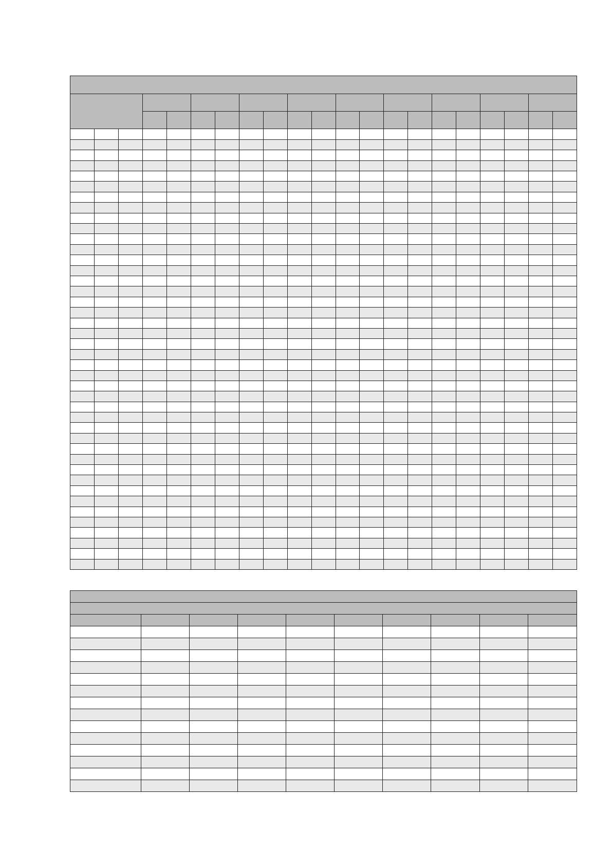
Table 2. Single acting actuator torque table
Actuator model
SPRING 3 bar 3.5 bar 4 bar 4.5 bar 5 bar 5.5 bar 6 bar 7 bar
Min Max Min Max Min Max Min Max Min Max Min Max Min Max Min Max Min Max
040 SR 30 464668810 10 12 11 13 13 15 15 17 16 19
040 SR 40 58254768710 912 11 14 12 15 14 17
040 SR 55 812 - - - -263859711 913 10 15
050 SR 30 610 710 10 13 12 16 15 18 18 21 20 24 23 26 26 29
050 SR 40 913 38611 913 12 16 14 19 17 21 20 24 22 27
050 SR 55 13 19 - - - - 3 9 5 12 815 11 17 14 20 16 23
063 SR 30 11 17 12 18 17 23 22 28 27 33 32 38 37 43 42 48 47 53
063 SR 40 15 24 - - 11 19 16 24 21 29 26 34 31 39 36 44 41 49
063 SR 55 23 35 ----517 10 22 15 27 20 32 25 37 30 42
080 SR 30 18 28 20 29 28 37 36 45 44 53 52 61 60 69 68 77 76 85
080 SR 40 24 37 11 24 19 32 27 40 35 47 43 55 51 63 59 71 67 79
080 SR 55 37 56 ----827 16 35 24 43 32 51 40 59 48 67
090 SR 30 29 44 32 47 45 60 57 72 70 85 83 98 95 111 108 123 121 136
090 SR 40 39 59 18 38 30 50 43 63 56 76 68 89 81 101 94 114 107 127
090 SR 55 58 89 ------25 56 38 69 51 81 64 94 76 107
100 SR 30 42 64 45 67 64 85 82 104 100 122 118 140 136 158 155 176 173 195
100 SR 40 55 84 25 54 43 72 61 90 80 108 98 127 116 145 134 163 152 181
100 SR 55 84 127 ------36 80 55 98 73 116 91 135 109 153
110 SR 30 52 79 56 83 79 106 101 128 124 151 146 173 169 196 192 219 214 241
110 SR 40 68 104 31 67 54 89 76 112 99 134 121 157 144 179 166 202 189 225
110 SR 55 104 158 - - 0 54 23 77 45 99 68 122 90 144 113 167 135 189
125 SR 30 72 113 74 115 106 146 137 178 168 209 199 240 231 271 262 303 293 334
125 SR 40 97 151 37 91 68 122 99 153 131 185 162 216 193 247 224 278 256 310
125 SR 55 135 211 - - 8 84 39 115 70 146 102 177 133 209 164 240 195 271
150 SR 30 121 195 117 191 169 242 221 294 273 346 325 398 377 450 429 502 480 554
150 SR 40 162 260 52 150 104 202 156 254 208 306 260 358 312 410 364 462 416 514
150 SR 55 226 363 - - 0 137 52 189 104 241 156 293 208 345 260 397 312 449
175 SR 30 168 274 176 283 251 358 326 433 401 508 476 583 551 658 626 733 701 808
175 SR 40 223 366 85 227 160 302 235 377 310 452 385 527 460 602 535 677 610 752
175 SR 55 313 512 - - 13 212 88 287 163 362 239 438 314 513 389 588 464 663
200 SR 30 235 425 259 448 373 562 487 676 601 790 715 904 829 1018 943 1132 1057 1246
200 SR 40 314 566 118 370 231 484 345 598 459 712 573 826 687 940 801 1054 915 1168
200 SR 55 439 793 - - 5 358 119 472 233 586 347 700 461 814 575 928 689 1042
250 SR 30 383 690 421 729 606 914 791 1099 977 1284 1162 1469 1347 1655 1532 1840 1717 2025
250 SR 40 510 920 191 601 376 786 561 971 747 1157 932 1342 1117 1527 1302 1712 1487 1897
250 SR 55 714 1288 - - 8 582 193 767 378 953 564 1138 749 1323 934 1508 1119 1693
300 SR 30 693 1055 634 995 915 1277 1196 1558 1478 1839 1759 2121 2040 2402 2322 2683 2603 2965
300 SR 40 924 1406 282 764 563 1046 845 1327 1126 1608 1408 1890 1689 2171 1970 2452 2252 2734
300 SR 55 1294 1969 - - 1 676 282 957 564 1239 845 1520 1126 1801 1408 2083 1689 2364
350 SR 30 948 1443 867 1362 1252 1747 1637 2132 2022 2517 2407 2902 2792 3287 3177 3672 3562 4057
350 SR 40 1264 1924 386 1046 771 1431 1156 1816 1541 2201 1926 2586 2311 2971 2696 3356 3081 3741
350 SR 55 1770 2694 - - 1 925 386 1310 771 1695 1156 2080 1541 2465 1926 2850 2311 3235
Table 3. Double acting actuator torque table
DOUBLE ACTING TORQUE (Nm)
Actuator model 2.5 bar 3 bar 3.5 bar 4 bar 4.5 bar 5 bar 5.5 bar 6 bar 7 bar
40 9 10 12 14 16 17 19 21 24
50 14 16 19 22 24 27 30 33 38
63 25 30 35 40 45 50 54 59 69
80 40 48 56 64 72 80 88 96 111
90 64 76 89 102 114 127 140 153 178
100 91 109 127 145 164 182 200 218 255
110 113 135 158 180 203 225 248 270 315
125 156 188 219 250 281 313 344 375 438
150 260 312 364 415 467 519 571 623 727
175 375 450 525 600 675 750 825 900 1050
200 570 684 798 912 1026 1140 1254 1368 1596
250 926 1111 1296 1482 1667 1852 2037 2222 2593
300 1407 1688 1970 2251 2532 2814 3095 3376 3939
350 1925 2310 2695 3080 3465 3850 4235 4620 5390
IMO-218 EN - Issue 8/20206
1.5 RECYCLING AND DISPOSAL
Most of the actuator parts can be recycled if sorted according
to material. Most parts have material marking. A material list is
supplied with the actuator. In addition, separate recycling and
disposal instructions are available from the manufacturer. An
actuator can also be returned to the manufacturer for recycling and
disposal against a fee.
1.6 DEFINITIONS
The following denitions given here are used in this document:
WARNING:
IF NOT OBSERVED, USER INCURS A HIGH RISK OF
SEVERE DAMAGE TO THE PRODUCT AND/OR FATAL
INJURY TO PERSONNEL.
CAUTION:
IF NOT OBSERVED, USER MAY INCUR DAMAGE TO
THE PRODUCT AND/OR INJURY TO PERSONNEL.
NOTE:
ADVISORY AND INFORMATION COMMENTS PROVIDED
TO ASSIST MAINTENANCE PERSONNEL TO CARRY
OUT MAINTENANCE PROCEDURES.
WARNING FOR ATEX:
IF NOT OBSERVED, USER INCURS A HIGH RISK OF
SEVERE DAMAGE TO ACTUATOR AND/OR FATAL
INJURY TO PERSONNEL.
NOTE:
ADVISORY AND INFORMATION COMMENTS PROVIDED
TO ASSIST MAINTENANCE PERSONNEL TO CARRY
OUT MAINTENANCE PROCEDURES.
WARNING FOR ATEX:
IF NOT OBSERVED, USER INCURS A HIGH RISK OF
SEVERE DAMAGE TO ACTUATOR AND/OR FATAL
INJURY TO PERSONNEL.
1.7 SAFETY PRECAUTIONS
CAUTION:
DON’T EXCEED THE PERMITTED VALUES!
EXCEEDING THE PERMITTED PRESSURE VALUE
MARKED ON THE ACTUATOR MAY CAUSE DAMAGE
AND LEAD TO UNCONTROLLED PRESSURE RELEASE
IN THE WORST CASE. DAMAGE TO THE EQUIPMENT
AND PERSONAL INJURY MAY RESULT.
CAUTION:
DON’T DISMANTLE A PRESSURIZED ACTUATOR!
DISMANTLING A PRESSURIZED ACTUATOR LEADS TO
UNCONTROLLED PRESSURE RELEASE. SHUT OFF
THE SUPPLY PRESSURE AND RELEASE PRESSURE
FROM THE CYLINDER BEFORE DISMANTLING THE
ACTUATOR. OTHERWISE, PERSONAL INJURY AND
DAMAGE TO EQUIPMENT MAY RESULT.
CAUTION:
FOLLOW THE INSTRUCTIONS GIVEN ON THE
ACTUATOR WARNING PLATES!
CAUTION:
BEFORE OPENING THE CYLINDER FASTENING
SCREWS (11), RELEASE SPRING TENSION DIRECTED
ON ACTUATOR WARNING PLATE AND IN THESE
INSTRUCTIONS!
CAUTION:
DON’T DISMANTLE THE SPRING MODULE!
DO NOT REMOVE THE SPRING MODULE WHILE THE
SPRING IS COMPRESSED OR UNDER PRESSURE.
CAUTION:
TAKE THE WEIGHT OF THE ACTUATOR OR VALVE
COMBINATION INTO ACCOUNT WHEN HANDLING IT!
LIFTING LUGS ON THE ACTUATOR ARE MEANT ONLY
FOR LIFTING ACTUATOR AND NOT COMPLETE VALVE
ASS EMB LY.
DO NOT LIFT THE VALVE COMBINATION FROM
THE ACTUATOR, POSITIONER, LIMIT SWITCH OR
THEIR PIPING. LIFT THE ACTUATOR AS DIRECTED
IN SECTION 2, LIFTING ROPES FOR A VALVE
COMBINATION SHOULD BE FASTENED AROUND IT.
THE WEIGHTS ARE SHOWN IN SECTION 9. DROPPING
MAY RESULT IN PERSONAL INJURY OR DAMAGE TO
TH E EQUI PM EN T.
WARNING FOR ATEX:
WHILE LIFTING ACTUATOR HOUSING SHOULD NOT
IMPACT ON THE OTHER LIGHT OR RUSTY METAL .
CAUTION:
POTENTIAL ELECTROSTATIC CHARGING HAZARD, DO
NOT RUB SURFACE WITH DRY CLOTH.
WARNING FOR ATEX:
INSPECT FOR PAINT DAMAGED, TO ENSURE
CONTINUED CORROSION PROTECTION.
ACTUATOR SPEED SHOULD NOT FASTER THAN
SPECIFIED IN THE FOLLOWING TABLE 4.
7IMO-218 EN - Issue 8/2020
Table 4.
Actuator Model Minimum operating time (seconds) for ATEX compliance
RNP 40 0.02
RNP 50 0.02
RNP 63 0.02
RNP 80 0.03
RNP 90 0.03
RNP 100 0.03
RNP 110 0.04
RNP 125 0.04
RNP 150 0.05
RNP 175 0.06
RNP 200 0.06
RNP 250 0.09
RNP 300 0.07
RNP 350 0.09
WARNING:
Valve on which actuator is installed should be earthed properly to
discharge static charge.
2. TRANSPORTATION AND
STORAGE
Make sure that the actuator and associated equipment have not
been damaged during transportation. Store the actuator carefully
before installation, preferably indoors in a dry place. Do not take
it to the installation site or remove the protective caps of ports for
piping until just before installation.
Lift the actuator as shown in Fig. 4: in a horizontal position from the
lifting lugs. Refer to Section 1.4 for weights.
LIFTING ARRANGMENT
RNP 200 / 250
RNP 300 / 350
Figure 4. Lifting the actuator
Upon receiving the product check the limit actuator and the
accompanying devices for any damage that may have occurred
during transport.
WARNING:
DO NOT USE THE DEVICE IF IT IS DAMAGED DURING
TRANSPORTATION!
IF THE DEVICE HAS SUFFERED DAMAGE DURING
TRANSPORTATION DO NOT INSTALL AND USE IT. IN
CASE OF NOTICING DAMAGE TO THE DEVICE UPON
RECEIVING IT PLEASE CONTACT THE SUPPLIER.
Store the actuator carefully. Storage indoors in a cool, dry place.
Temperature limit for the storing is from 4 °C to 40 °C. The actuator
should be left in its original packing until it is required for the use.
Do not remove protective plugs until installing the actuator.
3. MOUNTING AND
DEMOUNTING
3.1 ACTUATOR GAS SUPPLY
Dry compressed air, nitrogen or natural gas (sweet) can be used
as supply medium, no oil spraying is needed. The air supply
connections are presented in the dimensional drawings in Chapter
9. The maximum supply pressure is depending the selected model.
3.2 INSTALLATION INFORMATION
Before installation please take care of the safety precautions
mentioned in the Section 1.7.
Ensure that the actuator will not be exposed to pressure in excess
to the maximum rating as indicated on the actuator nameplate or
technical documents.
Ensure that throughout the installation that there are no leaks of the
supply media.
The maximum operating temperature for the actuator depends
on individual build of actuator. Refer nameplate for operating
temperature range.
Ensure that the maximum operating temperature as indicated on
the nameplate is not exceeded during operation, transportation or
storage of the actuator.
The environment and surrounding should not aect or limit the
operational safety of the product.
Ensure the product is protected against impact, vibration or any kind
of movement during operation, transportation and storage.
Product should not be installed in hazardous area that is not
compatible with the gas group and temperate class indicated on the
nameplate.
RNP series actuators can be mounted on valve in any desired
position. However it is recommended to align the centerline of the
pneumatic cylinder module along the pipeline.
Ensure proper tightening of fasteners and mounting accessories to
avoid loosening during operation.
All the tubing, tting and actuation media should be free from
contamination and ltered to the desired level. Quality of media
should be as per ISO 8573-1 [5:3:4]. For additional information
consult Neles.
Ensure proper adjustments of the stopper bolt to desired opening
and closing of the valve.
IMO-218 EN - Issue 8/20208
Once proper installation is done, check for smooth continuous
operation. If undesired operation occurs, check for correct pressure
and volume ow.
NOTE:
FLOW MAY BE RESTRICTED BY UNDERSIZE TUBING
OR FITTING. THESE MAY THROTTLE THE FLOW
RESULTING IN REDUCE PRESSURE OR VOLUME
CAUSING INTERMITTENT OR UNDESIRED MOVEMENT.
3.3 MOUNTING THE ACTUATOR
ON THE VALVE
CAUTION:
BE AWARE OF THE CUTTING MOVEMENT OF THE
VALVE!
Install the actuator so that the shaft of the valve or any other device
to be actuated goes into the shaft bore of the
actuator. If the bore is larger than the shaft diameter, use an adapter /
sleeve / bushing. RNP series actuator has double square female shaft
bore. Square bores are at an angle of 45° which allows the installation
position of the actuator to be changed in relation to the valve.
Figure 5. Ways to install the actuator
RNP series actuator can be mounted on valve in any desired
position. However it is recommended to align the centerline of
the pneumatic actuator along the process pipeline. When the
installation position of the actuator is altered, the arrow indicating
the operating direction must be turned to correspond with the actual
operation of the valve.
When necessary, lubricate the actuator bore and collar with grease
or anti-corrosive agent to prevent it from jamming due to rust.
The actuator must not be allowed to come in contact with the
pipework, because the vibrations may damage it or cause
unsatisfactory operation.
In some cases, e.g. when using large actuators or with extensive
pipework vibrations, the actuator should be supported. Consult
Neles for instructions.
If the actuator is used with devices other than Neles valves, any
additional parts attached to the actuator must be properly protected.
3.4 OPERATING DIRECTIONS
NOTE:
SEPARATE INSTRUCTIONS ARE AVAILABLE FOR
ADJUSTING THE CLOSE LIMIT OF METAL-SEATED
BUTTERLY VALVES. REFER TO THE INSTALLATION,
OPERATING AND MAINTENANCE INSTRUCTIONS OF
THE VALVE.
RNP DOUBLE ACTING VERSION
Double acting actuator should be in close position when installed on
the valve in close position.
RNP SPRING RETURN VERSION
Install spring return actuator in fail safe position on the valve being
in corresponding position. In other words: spring to close actuator in
close position and valve in close position / spring to open actuator in
open position and valve in open position.
DEMOUNTING THE ACTUATOR FROM THE VALVE
CAUTION:
DEPRESSURISE THE ACTUATOR BEFORE STARTING
DEMOUNTING!
The actuator must be de-pressurized and the supply air
disconnected. Unscrew the actuator-side screws of
the bracket and pull the actuator o the valve shaft. For larger
actuators this is best done lifting the actuator from lifting lugs by
crane. Note the mutual positioning of the valve and the actuator to
ensure correct functioning after reassembly.
9IMO-218 EN - Issue 8/2020
3.5 SETTING
All actuators are factory set to 0 and 90 degrees. Even minor
adjustments of the stroke adjustment screws (5A and 5B) will result
in over travel or incomplete travel of the pinion.
Loose nut #13 and rotate screw 5A in counter clock wise direction
(CCW) to set over travel (close)
Loose nut #13 and rotate screw 5A in clock wise direction (CW) to
set under travel (close).
Loose nut #13 and rotate screw 5B in counter clock wise direction
(CCW) to set over travel (open).
Loose nut #13 and rotate screw 5B in clock wise direction (CW) to
set under travel (open).
Pie chart below shows the exact degree of pinion travel.
Table below shows required revolution of the bolts for 1° travel of
pinion for each actuator.
Actuator
size
Revolution of bolts
for 1° travel of pinion
RNP 40 Half quarter turn
RNP 50 Half quarter turn
RNP 63 Half quarter turn
RNP 80 Quarter turn
RNP 90 Quarter turn
RNP 100 Quarter turn
RNP 110 Quarter turn
RNP 125 Quarter turn
RNP 150 Quarter turn
RNP 175 Quarter turn
RNP 200 Quarter turn
RNP 250 Quarter turn
RNP 300 Quarter turn
RNP 350 Quarter turn
4. MAINTENANCE
4.1 MAINTENANCE GENERAL
CAUTION:
OBSERVE THE SAFETY PRECAUTIONS MENTIONED IN
SECTION 1.7 BEFORE MAINTENANCE!
Although Neles actuators are designed to work under severe
conditions, proper preventative maintenance Can signicantly help
to prevent unplanned downtime and in real terms reduce the total
cost of ownership. Neles recommends inspecting the actuators at
least every ve (5) years. The inspection and maintenance interval
depend on the actual application and process condition. The
inspection and maintenance intervals can be specied together with
your local Neles experts.
During this periodic inspection the parts detailed in the Spare Part
Set should be replaced. Time in storage should be included in the
inspection interval.
If maintenance assistance is required, please contact your local
Neles oce. The part numbers in parentheses () in the text refer
to the exploded view and to the parts list in Section 8, unless
otherwise stated.
IMO-218 EN - Issue 8/202010
This procedure is applicable with the understanding that all
pneumatic pressure has been removed from the actuator.
Remove all piping and mounted accessories that will interfere with
the module that are to be worked on.
When removing seals from seal grooves; use a commercial seal
removing tool or a small screwdriver with sharp corners rounded o.
Use a non-hardening thread sealant on all pipe threads.
CAUTION:
APPLY THE THREAD SEALANT AS PER THE
MANUFACTURER’S INSTRUCTIONS.
All parts should be thoroughly inspected for excessive wear, stress
cracking and pitting. Attention should be directed to threads, sealing
surfaces and areas that will subjected to sliding and rotating motion.
Actuator parts that reect any of the above listed characteristics
should be replaced with new parts.
Neles recommends that disassembly of the actuator modules
should be done in a clean area on a workbench.
After reassembly, the actuator needs to be stroke for several times
to ensure the desired function and safety.
If you remove the stop screw, adjust the limits after lubrication or
grease lling!
Before doing maintenance, check actuator for leakage at inlet,
outlet and cover.
NOTE:
IN ORDER TO ENSURE SAFE AND EFFECTIVE
OPERATION, ALWAYS USE ORIGINAL SPARE PARTS
TO MAKE SURE THAT THE ACTUATOR FUNCTIONS AS
INTENDED.
NOTE:
WHEN SENDING GOODS TO THE MANUFACTURER
FOR REPAIR, DO NOT DISASSEMBLE THEM.
NOTE:
FOR SAFETY REASONS, REPLACE BOLTING IF THE
THREADS ARE DAMAGED, HAVE BEEN HEATED,
STRETCHED OR CORRODED.
4.2 MAINTENANCE
PRECAUTIONS OF THE
RNP_E_C AND RNP_E_A
ACTUATOR
CAUTION:
DON’T DISMANTLE A PRESSURIZED ACTUATOR!
CAUTION:
TO RELEASE SPRING TENSION, THE SPRING
DIRECTION STOP SCREW AT THE CENTRAL BLOCK
MUST BE REMOVED BEFORE THE CYLINDER
FASTENING SCREWS ARE OPENED!
CAUTION:
DON’T DISMANTLE THE SPRING PACKAGE!
THE SPRING PACKAGE WITHIN THE CYLINDER IS
PRELOADED. NEVER OPEN OR DISMANTLE THE
SPRING PACKAGE. THE SPRING MODULE IS ALWAYS
DELIVERED AS A PRE-ASSEMBLED PACKAGE.
The actuator has a caution sticker. When servicing the unit, check
that the sticker is in place and legible. See Fig. 6.
Figure 6. Caution sticker of the RNP series size 040 - 110
5. OPERATION
Actuator is tted with NPT connection.
Provide air connections using proper ttings.
Air supply to meet above specications and not to exceed 8 Bar.
Ensure air supply pressure is regulated to ensure maximum air
supply is not exceeded.
5.1 OPERATING PRINCIPLE
(STANDARD MODE) FOR
DOUBLE ACTING
Both ports A and B are used as inlet ports.
When air is supplied to Port A, the pistons are moved away from
each other, and the pinion is rotated CCW.
11IMO-218 EN - Issue 8/2020
When air is supplied through Port B, the pistons come closer
and return to their home position, rotating the pinion CW.
5.2 OPERATING PRINCIPLE
(STANDARD MODE) FOR
SPRING RETURN– FAIL CW
Port A is used as inlet.
When air is supplied to Port A, the pistons are moved away
from each other, the springs are compressed, and the pinion is
rotated CCW.
When the air is exhausted through Port A, the springs return the
pistons to the home position, rotating the pinion CW.
6. MAINTENANCE
6.1 LUBRICATION
All the mountings, accessories and spare parts used or replaced
must be original from Neles.
Use Neles recommended grease for greasing rack and seals.
Apply the grease with soft brush.
NOTE:
Carry out maintenance involving disassembling of actuator in a
safe indoor place free from dust, water.
Ensure that air supply has been disconnected.
Ensure proper lifting procedures are followed when moving or
lifting actuators.
DO NOT use accessory, mounting holes on top of actuator for lifting.
If actuator is spring return, ensure actuator is in the failed
position and springs are de- energized before disassembling.
7. DISASSEMBLY
Refer the view on page 22/23/24.
a. Loosen the lock nuts #13, and remove stroke adjustment
screws #5A and #5B, washers #10, and o-rings #23.
b. Loosen the cover bolts #9 on each end cap gradually in 1– 3 -
2 – 4 sequence. The bolts are long enough to retain the cover
connected to the body until the spring tension is fully released.
IMO-218 EN - Issue 8/202012
CAUTION:
SPRING RETURN ACTUATOR END CAPS ARE UNDER
SPRING TENSION. CAUTION MUST BE USED WHILE
REMOVING END CAP BOLTS AND END CAPS. IT IS
RECOMMENDED TO PUT ACTUATOR INTO A PRESS
DURING REMOVAL OF END CAPS TO ENSURE SAFE
RELEASE OF SPRING TENSION.
c. Rotate the pinion #2 in the counter clockwise direction (For
double acting & Spring return fail safe close actuators) until the
pinion becomes free.
Rotate the pinion #2 in the clockwise direction (For Spring
return fail safe open actuators) until the pinion becomes free.
d. Pull the piston out from each side by holding with pliers.
CAUTION: NEVER attempt to remove pistons from actuator body
using air pressure when the end caps have been removed!!
e. Remove external circlip # 17 and then washers #10 and #19.
f. Tap the pinion gently from the top using a rubber mallet until
the pinion is approximately half way into the body. Remove the
top pinion seal #14 and the top pinion bearing #18. Remove
the cam #08.
13IMO-218 EN - Issue 8/2020
g. Pull the pinion the rest of the way out of the body. Check the
pinion bearing #5 for its condition. If removal and replacement of
the pinion bearings are required, carefully push the pinion bearing
o with the help of a screw driver and remove from the body.
Remove the rack bearing #12. Remove the bottom pinion bearing
#15, the bottom pinion seal #11, and the end cap seals #16.
8. ASSEMBLY FOR DOUBLE
ACTING & STANDARD
MODE SPRING SPRING
RETURN
(FAIL CLOCKWISE, CW)
NOTE:
Follow the sequences as given below to ensure proper
assembly.
Use only the recommended accessories and lubricants.
a. Clean all the parts.
b. Fit bottom pinion bearing #15 and bottom pinion seal #11
on to the pinion #2. Apply recommended grease over the
pinion bearing surface #15 and on the bottom pinion seal #11.
Apply a thin coat all over the surface; avoid excess grease.
Insert pinion carefully into the body #1 from the bottom,
approximately half way.
c. While installation of cam #8 match cam slot with pinion #2 slot
properly as shown.
d. Install top pinion seal #14 on pinion and apply a light layer
of grease. Install top pinion bearing #18 on pinion. Push the
pinion the rest of the way into the body.
Apply gentle force while rotating the pinion to facilitate the
insertion.
e. Install polyacetal washer #10, SS washer #19, and external
circlip #17 on top of pinion. Check for free rotation of pinion.
f. Apply recommended grease over the bore of the body; avoid
excess grease.
IMO-218 EN - Issue 8/202014
g. Rotate the pinion so that the dot on the pinion is positioned close to the two dots on the top pad of the actuator body
for accurate pinion alignment.
For counterclockwise (CCW) assembly dot on the pinion is positioned close to the two dots on the top pad of the actuator body,
then assemble piston.
For clockwise (CW) assembly dot on the pinion is positioned close to the single dot on the top pad of the actuator body,
then assemble piston
h. Fit rack bearing in piston with rack. i. Apply grease on outer surface of rack bearing and put some
grease in pocket
15IMO-218 EN - Issue 8/2020
j. Ensure both the pistons are engaged in the same position.
Same amount of gap between the face of each piston and the
end of the body will conrm this.
k. For spring return actuators, insert the springs.
NOTE:
While assembling springs and end caps on spring return
actuators, it is necessary to have the actuator body in the
vertical position. This is required to ensure that springs remain
properly aligned and centered during assembly.
q. Fix the seals #16 on the left and right end caps and install
on to body. Ensure the air ports on the end caps are aligned
properly. Ensure uniform tightening sequence of the bolts
1 – 3 – 2 – 4.
r. Install stroke adjustment screws #5A and 5B with o-rings #23,
washers #24, and lock nuts #13.
s. Apply air to Port A to move pistons to the extended 90 degree
position.
t. Adjust stroke adjustment screw #5A for the 90 degree position,
turning clockwise until the screw is barely touching the piston.
Tighten the lock nut.
u. For spring return actuators, release the air pressure, for double
acting actuators, apply air to Port B. This will bring the pistons
back to the 0 degree position.
v. Adjust the stroke adjustment screw #5A for the 0 degree
position, turning clockwise until the bolt is barely touching the
piston. Tighten the lock nut.
w. Apply air as required to stroke the actuator several times to
conrm that the stroke adjustment screws are set correctly and
ensure that there is no air leakage from any of the seals.
x. Re-install or repack for storage (see section 11 for Packaging
and Storage).
y. For ower spring structure follow the instructions same as that
of concentric structure.
z. For positioning of ower spring structure please refer g.
WARNINGS
Use only genuine spares parts supplied by Neles.
Use only the recommended accessories and lubricants.
Install, operate and maintain as per the instructions and
recommendations of this manual.
No metal should fall on actuator body to ensure no spark
generation in actuator body.
All accessories should have explosion protection or
intrinsically safe.
Any deviation from the above warnings will cease the
responsibilities of Neles.
IMO-218 EN - Issue 8/202016
9. MALFUNCTIONS
Table 5. lists malfunctions that might occur after prolonged use
Symptom Possible cause Action
Irregular or slow operation Low supply pressure Make sure that supply pressure complies with minimum torque required by
valve. Check that supply air pipes are large enough.
Positioner fault Check positioner operation.
Valve fault Check that valve functions properly without actuator.
Incorrect actuator rating Contact manufacturer to check rating.
Leak in piston or piston rod seal Replace seals.
Cylinder damaged by impurities Note installation position recommendation. Replace cylinder if damaged.
Worn-out actuator bearings Check bearings. Replace bearings when neccessary.
Moving parts corroded in harsh, humid conditions Replace the corroded parts.
Backlash in joint between actuator and valve Replace parts as necessary.
10. TOOLS
For maintenance of the RNP series actuator, you will need a few
common tools.
10.1 TIGHTENING TORQUE
TABLE
Actuator model Bolt size (#9) Tightening torque (Nm)
RNP 40
M6 8
RNP 50
RNP 63
RNP 80
RNP 90
M8 20
RNP 100
RNP 110
RNP 125
RNP 150 M10 40
RNP 175
RNP 200
M12 70
RNP 250
RNP 300
RNP 350
11. ORDERING SPARE PARTS
NOTE:
USE ONLY ORIGINAL SPARE PARTS. THIS ENSURES
PROPER FUNCTIONING OF THE ACTUATOR.
When ordering spare parts, always include following information.
Type code, sales order number, serial number
Number of the parts list, part number, name of the part and
required quantity
This information can be found from the identication plate or
documents.
17IMO-218 EN - Issue 8/2020
12. EXPLODED VIEWS AND PARTS LIST
12.1 DOUBLE ACTING VERSION
DOUBLE ACTING RNP 40...110 DA
BILL OF MATERIALS AND PARTS LIST
ITEM NO. UNIT QTY. PART DESCRIPTION MATERIAL SPECIFICATION CORROSION PROTECTION
1 1 BODY ALUMINIUM 6063T5/T6; 6005-T6/T5 HARD ANODISED
2♦ 1 PINION STEEL EN8 ZINC FLACKING
3♦ 2 PISTON WITH RACK ALUMINIUM LM13 HARD ANODISED
4♦ 2 COVER ALUMINIUM LM6 EPOXY POWDER COATED
5 2 STOPPER BOLT STAINLESS STEEL AISI304
6*# 2 O-RING (PISTON) NITRILE RUBBER NBR 70SHORE A
7# 2 PISTON STRIP POLYACETAL -
8♦ 1 CAM CAST CARBON STEEL ASTM A216 GR WCB OLIVE PASSIVATION
9 8 COVER BOLT STAINLESS STEEL AISI304
10 1 WASHER (PINION) POLYACETAL -
11*# 1 O-RING (PINION BOTTOM) NITRILE RUBBER NBR 70SHORE A
12 2 RACK BEARING POLYACETAL -
13 2 NUT (STOPER BOLT) STAINLESS STEEL AISI304
14*# 1 O-RING (PINION TOP) NITRILE RUBBER NBR 70SHORE A
15 1 PINION STRIP POLYACETAL -
16# 2 COVER SEAL NITRILE RUBBER NBR 70SHORE A
17 1 CIRCLIP (PINION) SPRING STEEL EN47-GR.3 ZINC FLAKING
18# 1 BEARING BUSH (CAM) POLYACETAL -
19 1 WASHER (PINION) STAINLESS STEEL AISI304
20*# 2 O-RING (STOPER BOLT) NITRILE RUBBER NBR 70SHORE A
21 2 WASHER (STOPER BOLT) STAINLESS STEEL AISI304
22 1 NAME PLATE POLYESTER ALUMINIUM -
23 2 DUST CAP PLASTIC -
NOTE. 1 * Marked components are the parts of the seal kit
2 # Marked components are the parts of repair kit.
3 ♦ Marked components are critical components.
IMO-218 EN - Issue 8/202018
DOUBLE ACTING RNP 125...175 DA
BILL OF MATERIALS AND PARTS LIST
ITEM NO. UNIT QTY. PART DESCRIPTION MATERIAL SPECIFICATION CORROSION PROTECTION
1 1 BODY ALUMINIUM 6063T5/T6; 6005-T6/T5 HARD ANODISED
2♦ 1 PINION STEEL EN8 ZINC FLACKING
3♦ 2 PISTON WITH RACK ALUMINIUM LM13 HARD ANODISED
4♦ 2 COVER ALUMINIUM LM6 EPOXY POWDER COATED
5 2 STOPPER BOLT STAINLESS STEEL AISI304
6*# 2 O-RING (PISTON) NITRILE RUBBER NBR 70SHORE A
7# 2 PISTON STRIP POLYACETAL -
8♦ 1 CAM CAST CARBON STEEL ASTM A216 GR WCB OLIVE PASSIVATION
9 8 COVER BOLT STAINLESS STEEL AISI304
10 1 WASHER (PINION) POLYACETAL -
11*# 1 O-RING (PINION BOTTOM) NITRILE RUBBER NBR 70SHORE A
12 2 RACK BEARING POLYACETAL -
13 2 NUT (STOPER BOLT) STAINLESS STEEL AISI304
14*# 1 O-RING (PINION TOP) NITRILE RUBBER NBR 70SHORE A
15 1 PINION STRIP POLYACETAL -
16# 2 COVER SEAL NITRILE RUBBER NBR 70SHORE A
17 1 CIRCLIP (PINION) SPRING STEEL EN47-GR.3 ZINC FLAKING
18# 1 BEARING BUSH (CAM) POLYACETAL -
19 1 WASHER (PINION) STAINLESS STEEL AISI304
20*# 2 O-RING (STOPER BOLT) NITRILE RUBBER NBR 70SHORE A
21 2 WASHER (STOPER BOLT) STAINLESS STEEL AISI304
22 1 NAME PLATE POLYESTER ALUMINIUM -
23 2 DUST CAP PLASTIC -
NOTE. 1 * Marked components are the parts of the seal kit
2 # Marked components are the parts of repair kit.
3 ♦ Marked components are critical components.
19IMO-218 EN - Issue 8/2020
DOUBLE ACTING RNP 200...250 DA
BILL OF MATERIALS AND PARTS LIST
ITEM NO. UNIT QTY. PART DESCRIPTION MATERIAL SPECIFICATION CORROSION PROTECTION
1 1 BODY ALUMINIUM 6063T5/T6; 6005-T6/T5 HARD ANODISED
2♦ 1 PINION STEEL EN8 ZINC FLACKING
3♦ 2 PISTON WITH RACK ALUMINIUM LM13 HARD ANODISED
4♦ 2 COVER ALUMINIUM LM6 EPOXY POWDER COATED
5 2 STOPPER BOLT STAINLESS STEEL AISI304
6*# 2 O-RING (PISTON) NITRILE RUBBER NBR 70SHORE A
7# 2 PISTON STRIP POLYACETAL -
8♦ 1 CAM CAST CARBON STEEL ASTM A216 GR WCB OLIVE PASSIVATION
9 16 COVER BOLT STAINLESS STEEL AISI304
10 1 WASHER (PINION) POLYACETAL -
11*# 1 O-RING (BOTTOM PINION) NITRILE RUBBER NBR 70SHORE A
12 2 RACK BEARING POLYACETAL -
13 2 NUT (STOPER BOLT) STAINLESS STEEL AISI304
14*# 1 O-RING (TOP PINION) NITRILE RUBBER NBR 70SHORE A
15 1 PINION STRIP POLYACETAL -
16# 2 COVER SEAL NITRILE RUBBER NBR 70SHORE A
17 1 CIRCLIP (PINION) SPRING STEEL EN47-GR.3 ZINC FLAKING
18# 1 BEARING BUSH (CAM) POLYACETAL -
19 1 WASHER (PINION) STAINLESS STEEL AISI304
20*# 2 O-RING (STOPER BOLT) NITRILE RUBBER NBR 70SHORE A
21 2 WASHER (STOPER BOLT) STAINLESS STEEL AISI304
22 1 NAME PLATE POLYESTER ALUMINIUM -
23 2 DUST CAP PLASTIC -
30 1 MANIFOLD ALUMINIUM 6351-T6
31 4 MANIFOLD BOLT STAINLESS STEEL AISI304
32 2 MANIFOLD ORING NITRILE RUBBER NBR 70SHORE A
NOTE. 1 * Marked components are the parts of the seal kit
2 # Marked components are the parts of repair kit.
3 ♦ Marked components are critical components.
IMO-218 EN - Issue 8/202020
DOUBLE ACTING RNP 300 - 350 DA
BILL OF MATERIALS AND PARTS LIST
ITEM NO. UNIT QTY. PART DESCRIPTION MATERIAL SPECIFICATION CORROSION PROTECTION
1 1 BODY ALUMINIUM 6063T5/T6; 6005-T6/T5 HARD ANODISED
2 ♦ 1 PINION STEEL EN8 ZINC FLACKING
3 ♦ 2 PISTON WITH RACK ALUMINIUM LM13 HARD ANODISED
4 ♦ 2 COVER ALUMINIUM LM6 EPOXY POWDER COATED
5 2 STOPPER BOLT STAINLESS STEEL AISI304
6*# 2 O-RING (PISTON) NITRILE RUBBER NBR 70SHORE A
7# 2 PISTON STRIP POLYACETAL -
8 ♦ 1 CAM CAST CARBON STEEL ASTM A216 GR WCB OLIVE PASSIVATION
9 16 COVER BOLT STAINLESS STEEL AISI304
10 2 WASHER (PINION) POLYACETAL -
11*# 1 O-RING (BOTTOM PINION) NITRILE RUBBER NBR 70SHORE A
12 4 RACK BEARING POLYACETAL -
13 2 NUT (STOPER BOLT) STAINLESS STEEL AISI304
14*# 1 O-RING (TOP PINION) NITRILE RUBBER NBR 70SHORE A
15 1 PINION STRIP POLYACETAL -
16# 2 COVER SEAL NITRILE RUBBER NBR 70SHORE A
17 1 CIRCLIP (PINION) SPRING STEEL EN47-GR.3 ZINC FLAKING
18# 1 BEARING BUSH (CAM) POLYACETAL -
19 1 WASHER (PINION) STAINLESS STEEL AISI304
20*# 2 O-RING (STOPER BOLT) NITRILE RUBBER NBR 70SHORE A
21 2 WASHER (STOPER BOLT) STAINLESS STEEL AISI304
22 1 NAME PLATE POLYESTER ALUMINIUM -
23 2 DUST CAP PLASTIC -
28 1 BEARING BUSH HOUSING ALUMINIUM 6063T5/T6; 6005-T6/T5
29 1 O-RING (BEARING BUSH HOUSING ) NITRILE RUBBER -
30 1 MANIFOLD ALUMINIUM 6351-T6
31 4 MANIFOLD BOLT STAINLESS STEEL AISI304
32 2 MANIFOLD O-RING NITRILE RUBBER -
33 2 O-RING SMALL (BODY) NITRILE RUBBER -
34 4 BEARING BUSH HOUSING BOLT STAINLESS STEEL AISI304
NOTE. 1 * Marked components are the parts of the seal kit
2 # Marked components are the parts of repair kit.
3 ♦ Marked components are critical components.
  • Page 1 1
  • Page 2 2
  • Page 3 3
  • Page 4 4
  • Page 5 5
  • Page 6 6
  • Page 7 7
  • Page 8 8
  • Page 9 9
  • Page 10 10
  • Page 11 11
  • Page 12 12
  • Page 13 13
  • Page 14 14
  • Page 15 15
  • Page 16 16
  • Page 17 17
  • Page 18 18
  • Page 19 19
  • Page 20 20
  • Page 21 21
  • Page 22 22
  • Page 23 23
  • Page 24 24
  • Page 25 25
  • Page 26 26
  • Page 27 27
  • Page 28 28

Neles Easyflow RNP40 Installation Maintenance And Operating Instructions

Type
Installation Maintenance And Operating Instructions

Neles Easyflow RNP40 is a pneumatic quarter turn cylinder actuator designed to automate various industrial processes requiring precise control of valves and dampers. Constructed from robust materials, it delivers reliable performance in demanding applications. Its compact design makes it suitable for space-constrained installations. With a wide range of torque capabilities from 4 Nm to 56 Nm and operating temperatures from -20°C to +80°C, the RNP40 actuator can meet diverse application requirements.

Ask a question and I''ll find the answer in the document

Finding information in a document is now easier with AI