Linear Power 2121 Owner's Manual And Installation Manual
- Category
- Audio amplifiers
- Type
- Owner's Manual And Installation Manual
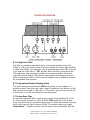
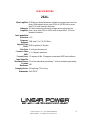
Linear Power 2121, a high-power bi-amplifier, offers versatile system integration for car audio enthusiasts. Its 120-watt RMS mono amplifier drives subwoofers, while the 120-watt RMS stereo amp powers main speakers. Variable phase coherent crossovers and independent gain controls provide precise audio tuning.
Linear Power 2121, a high-power bi-amplifier, offers versatile system integration for car audio enthusiasts. Its 120-watt RMS mono amplifier drives subwoofers, while the 120-watt RMS stereo amp powers main speakers. Variable phase coherent crossovers and independent gain controls provide precise audio tuning.


-
 1
1
-
 2
2
-
 3
3
-
 4
4
-
 5
5
-
 6
6
-
 7
7
-
 8
8
-
 9
9


Linear Power 2121 Owner's Manual And Installation Manual
- Category
- Audio amplifiers
- Type
- Owner's Manual And Installation Manual
Linear Power 2121, a high-power bi-amplifier, offers versatile system integration for car audio enthusiasts. Its 120-watt RMS mono amplifier drives subwoofers, while the 120-watt RMS stereo amp powers main speakers. Variable phase coherent crossovers and independent gain controls provide precise audio tuning.
Ask a question and I''ll find the answer in the document
Finding information in a document is now easier with AI
Related papers


Other documents
-
 Rockford Fosgate Power 250.2 User manual
-
PowerBass XL User manual
-
 Rockford Fosgate 55.2 User manual
-
 Rockford Fosgate 250 Series Installation & Operation Manual
-
 Rockford Fosgate Punch 100.2 Operations & Installation Manual
-
Orion Car Audio HP-2300 User manual
-
Orion West Coast Customs WCC-1600.2 User manual
-
-
 Rockford Fosgate 50.2 User manual
-
Diamond Audio Technology Power 250.2 User manual


