user maNual
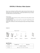
CLR2
X.LiNK-S1

Contents
• Introduction 3
• Safety Precautions 4
• Overview 5
• Characteristics 6
• Description Transmitter 7
• Description Receiver 8
• Operation 9
• Antenna Positioning 10
• Features 10
• Maintenance 15
• Troubleshooting 15
• Technical Specications 16
• Regulatory Information 17
• Notes 19
In all EU member states, operation of 5150-5250MHz is restricted
to indoor use only.
2

Congratulations on purchasing the
DC-LINK video transmission system!
Please read this manual carefully before operating your product. You can also
access this through our website: www.dwarfconnection.com
Also read the safety information enclosed with your DwarfConnection product,
as it contains more detailed information on product and health safety!
The technology contained in this product, including the device itself as well as
related software and trademarks, is protected by law. Any duplication or repro-
duction without the written permission of the copyright owner is prohibited, in
part or in full. All third-party brands or copyrights mentioned in this manual are
the property of their respective owners.
This manual is valid for:
DC-LINK-CLR2, DC-LINK-CLR2.MKII
DC-X.LINK-S1, DC-X.LINK-S1.MKII
Warranty
This product has a limited warranty of one year, starting from the date
of purchase. Warranty may be voided by:
• Physical damage of the product
• Any damage caused by improper use, maintenance or storage
• Damage resulting from the use of incorrect power supplies
• Damage not related to the design of the product or the quality
of its manufacture
For more information about warranty procedures please contact your retailer
or simply ask us.
3
EN

Safety Precautions
WARNING: READ BEFORE USE TO REDUCE THE RISK OF PERSONAL INJURY OR PROPERTY
DAMAGE, INCLUDING DAMAGE TO YOUR TRANSMITTER/RECEIVER AND OTHER POTENTIAL
HAZARDS.
HANDLING
Handle your DC-LINK system with care. You may damage the devices if you
disassemble, drop, bend, burn, crush or otherwise subject them to un necessary
force. Do not use a device with a damaged enclosure. Using a damaged
product may cause injury. Do not expose your devices to liquids of any kind!
This can cause a short circuit and overheating. If your devices do come
into contact with liquids, do not attempt to dry them using an external heat
source. If the device comes into contact with liquid or corrosive chemicals,
immediately turn off the power and remove the power supply. Do not operate
the device near re, gas lines or electrical mains or in high humidity or dusty
surroundings.
Do not block or otherwise impede ventilation slots or unused connectors, as this
may result in a short circuit, re or electric shock.
DC-LINK systems are designed to work in ambient temperatures between
0° and 40°C / 32° to 100°F and should be stored between ambient
temperatures of -20° and 60°C / 0° and 140°F. Ensure sufcient ventilation when
operating your DC-LINK system in warm temperatures to prevent overheating.
Do not leave your devices in places in which the temperature may exceed
60°C / 140°F as this may damage the product or pose a potential re risk.
Keep your device away from heat sources and out of direct sunlight. If your
device becomes too hot, disconnect it from its power source if it is plugged in,
move it to a cooler place, and do not use it until it has cooled. If you accidently
operated your DC-LINK system at temperatures lower than 0° C / 32° F try to
avoid condensation water: Do not allow your device to cool down in the cold!
Put your device in the case immediately after turning it off!
CARE & CLEANING
Unplug the product and power adapter before cleaning, during lightning
storms, or when unused for extended periods of time. Use a clean, soft, and
dry cloth to clean devices and their accessories. Do not use any chemical
detergent, powder, or other chemical agents (such as alcohol or benzene)
to clean the product or accessories.
REPAIR, SERVICE & SUPPORT
Disassembling the devices may cause injury to you or damage to your device.
Do not attempt to repair your DC-LINK system yourself. Opening your device
voids warranty. If devices cease working or have been damaged, contact our
support team.
4

PROLONGED HEAT EXPOSURE
Your DC-LINK system generates heat during normal operation and complies
with applicable surface temperature standards and limits. Avoid prolonged,
direct or indirect skin contact when the devices are in use because exposing
skin to hot surfaces for a long period of time may cause discomfort or burns.
ENVIRONMENTAL RESTRICTIONS
To prevent damage to your DC-LINK system, do not use or store the devices or
accessories in dusty, smoky, damp, or dirty environments. Leaving the devices
in places in which the temperature may exceed 60°C / 140°F may cause da-
mage to the devices or pose a re risk.
RADIO FREQUENCE INTERFERENCE
Observe rules that prohibit the use of wireless technology in certain environ-
ments. Your devices are designed to comply with regulations governing radio
frequency emissions but use of such systems can negatively affect other elect-
ronic equipment.
RECYCLING
Please recycle all packaging, devices and accessories in accordance with U.S.
regulations.
Overview
The DC-LINK-CLR2 is a high-performance WHDI video transmission system which
transmits uncompressed video and audio signals up to 300 m / 1,000 ft with no
latency (< 0.001 s delay).
Due to the conscious decision not to implement DFS (Dynamic Frequency
Selection) the device has a longer range, greater stability and better usability
than comparable systems that DO use DFS.
The transmitter and receiver both have 3G-SDI and HDMI connectors (Plug &
Play). When a video source is attached, the transmitter automatically selects
the input (SDI is prioritized). The receiver’s 3G-SDI and HDMI outputs can be
used simultaneously.
5
EN

Characteristics
• Max. transmission range 300m/1000ft line of sight
• Rapid and reliable connectivity, no need for complex pairing
• Real-time transmission with no latency (< 0.001s)
• Uncompressed transmission. 10-bit, 4:2:2 transmissions via 3G-SDI and HDMI
without format conversion
• Supports formats up to and including 1080p 60Hz
• 2- channel audio transmission, embedded audio transmission
on CH1 & CH2 via SDI and HDMI
• Operates within the license-free 5GHz ISM band, frequency range
from 5.1 to 5.9GHz
• Multicast support 1:1 or 1:n transmissions with up to four parallel systems
• Metadata and Time Code transmission*
• High grade aluminium casing: extremely durable and heat regulating
• Variable Input Voltage from 7,2-18,0V DC allows the system to be operated
with a variety of batteries or power supplies
• Status displays for DC power, video and RSSI signal strength
• 1/4“ tripod mount
• Battery adapter plate (V-mount / NPF) is available as an optional accessory
and can easily be mounted to the back
• Plug-and-Play design. Ready to use without the need for complex
conguration
• 1 Year warranty by manufacturer
* Metadata support available for most cameras and industry standard video assist solutions
(such as QTAKE).
6

Product Description
CLR2 Transmitter
1) 1/4“ Tripod Mount
2) Antenna Connection: SMA (male) Connector
3) Menu Button
4) Control Buttons
5) OLED display
6) Power Switch
7) SDI-IN: 3G/HD/SD-SDI Input, (BNC Female Connector)
8) SDI LOOP-OUT: 3G/HD/SD-SDI Output, (BNC Female Connector)
9) HDMI-IN: HDMI Input (Type A Female Connector)
10) DC-IN: 7,2 – 18,0V DC
11) Mini USB: For rmware upgrade
7
EN

Product Description
CLR2 and X.LINK-S1 Receiver
1) 1/4“ Tripod Mount
2) RSSI Status Display: Signal Strength
3) Menu Button
4) Control Buttons
5) OLED display
6) Power Switch
7) HDMI-OUT: HDMI Output (Type A Female Connector)
8) Dual SDI-OUT: 3G/HD/SD-SDI Output, (BNC Female Connector)
9) DC-IN: 7,2 – 18,0V DC
10) Mini USB: For rmware upgrade
8

Scope of Delivery
DC-LINK-CLR2 DC-X.LINK-S1
1x Transmitter 1x Receiver
1x Receiver 1x D-Tap cable 4pin
3x External Antenna 1x Magic arm with 1/4“ screw
2x D-Tap cable 4pin 1x Hotshoe Mount
1x Magic arm with 1/4“ screw Quick Start Guide
1x Hotshoe Mount USB ash drive with product manual
Quick Start Guide
USB ash drive with product manual
Operation
1. Connect the antennas to the SMA male connectors (2) of your devices.
2. There is a 1⁄4“ tripod mount at the base of the transmitter if required.
3. Power your devices with the enclosed power supplies or use the enclosed
D-Tap cables to connect to a battery. Only use 4-pin cables provided by
DwarfConnection to power your DC-LINK system! Other cables might cause
damage of your products!
4. Turn on your devices.
5. Make sure transmitter and receiver are set to the same channel.
Switch channels if necessary. (Find detailed instructions in “Features”)
Signal Distribution
Connect the camera’s SDI or HDMI output to the transmitter’s SDI or HDMI input.
If both SDI and HDMI inputs are active, the transmitter will prioritize the
SDI signal.
Connect the receiver’s SDI or HDMI output to the SDI or HDMI input of the
monitoring/recording device. During active transmission, both the SDI and the
HDMI output on the receiver can be used simultaneously.
Make sure that the antennas are connected rmly, and all other connections
are stable. Only use high quality 7,2 - 18,0V batteries.
9
EN

Antenna Positioning
Position the antennas on transmitter and receiver as shown in the illustration.
This ensures the best possible RF performance.
Install the transmitter and the receiver as high as possible (at least 2 meters
above ground level) to maintain a good line-of-sight. During operation,
try to keep the transmitter and the receiver at similar heights.
Avoid obstacles such as walls, trees, water and steel structures between
transmitter and receiver.
The connection is at its strongest when the at surfaces of the transmitter and
receiver face each other.
Find more information on how to optimize your wireless setup in the WHDI guide
on our website.
10

Display Status Description
RSSI 0-1 LEDs Radio signal strength is weak and artefacts
are visible in the video signal
2-3 LEDs Radio signal strength is normal and video
quality is good
4-5 LEDs Radio signal strength is very strong and video
quality is very good
Features
Menu Navigation
Use the MENU button to easily navigate through the sub menus of your DC-LINK
device. Press several times until the referring indicator is ashing. Then use + and
– to change the state and conrm with MENU.
OLED Display
The OLED Display shows all important information on the transmitter and the
receiver. To make any changes to your settings, use MENU to navigate to the
OLED Menu. Then use + and – to make your changes and conrm with MENU.
Received Signal Strangth Indicator (RSSI)
The RSSI display shows the strength of the signal, allowing the operator to
check, if the system is working properly. On MKII devices, the RSSI lights are
turned off in Dark Mode. To learn more about Dark Mode, please read the cor-
responding section of this manual.
Choosing a Channel
To choose a channel on the transmitter/receiver press MENU and select with
the + or - button. Press MENU again to conrm.
The system works on 10 channels in the license-free 5 GHz ISM frequency band,
using numbers 0-9.
On MKII receivers you can choose from 41 different channels. This is due to Multi
Brand Connectivity, which makes your DC-LINK receiver compatible with mul-
tiple other Brands. When working with a DwarfConnection transmitter, always
use channels 0-9! To learn more about Multi Brand Connectivity, please read
11
EN

the corresponding section of this manual.
Transmitter and receiver have to be set to the same channel to work. If several
systems are used at the same time, do not use neighboring channels to avoid
interferences. A maximum number of 4 systems can be used simultaneously.
Master Channel Selection (for all MKII devices)
All receivers on the same channel will react to channel changes of the trans-
mitter and follow automatically. Of course, a receiver can switch to another
channel independently at any time.
Multi Brand Connectivity (for MKII receivers)
All MKII receivers are equipped with DwarfConnections’s unique Multi Brand
Connectivity Feature that makes them compatible with most common non-DFS
WHDI wireless video systems on the market by letting you choose from different
frequency sets. This is as easy as choosing a channel:
Use the MENU button to go to channel selection
Choose a channel from different frequency sets using the + and – buttons.
The letter on your display shows the frequency set, the number shows the chan-
nel. The channels used by DwarfConnection transmitters, do NOT show a letter.
Therefore, when working with a DC-LINK transmitter, choose from channel 0 to 9
on your receiver.
Besides the DwarfConnection frequencys there are 31 more channels: A0-A9,
B0-B9, C0-C9 and CA. These frequency sets correspond with the channel sets,
other manufacturers are using.
The channel sets and referring frequencies are:
0-9 (DwarfConnection):
5550, 5590, 5630, 5670, 5150, 5190, 5230, 5270, 5310, 5510
A0-A9:
5825, 5190, 5230, 5755, 5795, 5745, 5765, 5775, 5785, 5805
B0-B9:
5130, 5210, 5250, 5330, 5370, 5450, 5530, 5610, 5690, 5770
C0-C9 plus CA:
5150, 5230, 5270, 5310, 5510, 5550, 5590, 5630, 5670, 5755, 5795
DC-Scan
DC-SCAN is a spectrum analyzer of the 5 GHz band and shows how busy the
respective channels are. Choose a free channel for proper performance before
operating your DC-LINK system.
To enter DC-SCAN, connect a monitor to the HDMI output of your receiver, then
12

CAUTION!
For a long product life, we highly recomment NOT to operate your DC-LINK
with permanently switched off fans. Whenever you are operating your
devices without cooling, monitor the temperature and make cooling
breakswhentheindicatoronyourdisplayisashing(60°C/140°F).
THE DEVICES DO NOT HAVE AN EMERGENCY OUT!
If you allow your devices to get too hot, you might cause serious damage of
your equipment.
press and hold the - button for 3 seconds. The frequency scanner is only availa-
ble on the HDMI output. To leave DC-SCAN press and hold the - button again.
When entering DC-SCAN from channel 0, it will also show you the antenna
check. Green antennas show awless operation, red antennas indicate that
there is a problem. Possible reasons might be improper connection or defective
antennas.
On Screen Display (OSD)
The OSD shows status information in case of transmission or signal problems. In
live situations the OSD might be distracting or simply unwanted. Therefore, it can
be turned off: Press the MENU button several times to navigate to the OSD menu
and select the desired state by using the + or - button. Conrm your selection
with MENU. An indicator on the OLED display of the receiver shows the OSD
state.
On MKII devices a Record Indicator within the OSD shows, whether the camera
is recording or not.
NOTE: This feature is bound to meta data support*.
Fan Control & Cinema Mode
Fan control allows you to turn the fans of the devices on or off to keep them
cool but also prevent unwanted noise. Press MENU to navigate to the fan menu
and select the desired state by using + or - .
AUTO indicates cinema mode, which triggers the fans using the start / stop ags
of the camera. Once you hit record, the fan will stop, ensuring total silence.
After recording, it will turn back on automatically. Cinema mode is bound to
metadata support* and only available with active SDI connection.
√ switches the fans on permanently. X switches the fans off.
Dark Mode
Dark Mode turns off any lights on your DC-LINK device. Press and hold + for 3
seconds to (de)activate Dark Mode. When in Encryption Mode, all receivers will
react to changes made on the transmitter and follow into or out of Dark Mode.
* Metadata support available for most cameras and industry standard video assist solutions
(such as QTAKE).
13
EN

Encryption (for all MKII devices)
In encryption mode, the transmitter sends an encoded signal that only linked
receivers can read, making it easy to protect condential content that is not
meant for everyone’s eyes.
To activate encryption mode, press and hold the MENU button on your device
to enter the encryption menu. Use + or – to check either ON or OFF and conrm
with MENU. The main menu will show either ENC or ENC to indicate whether
encryption is on or off.
To link your devices, set your transmitter and all the receivers to the same chan-
nel, then activate encryption on your transmitter. All receivers will follow into en-
cryption mode automatically. Settings remain active after turning your devices
off. This means that ENC can be prepared prior to shooting and will stay active
unless you turn it off.
A linked receiver does not HAVE to stay linked. To take a receiver out of the en-
crypted system, simply turn off ENC. Then you can easily access another (unen-
crypted) transmitter’s images by choosing the referring channel within seconds.
To link back to the previous (encrypted) transmitter, turn ENC on again.
IMPORTANT:
Switching back and forth between two encrypted systems is not possible.
You cannot slip into an encrypted wireless system, if your receiver was not initi-
ally linked to the transmitter. If you want to add a new receiver to an encrypted
system, you need to link the whole system again.
14

Maintenance
Please do not attempt to repair, modify or alter these devices under any
circumstances.
Clean the devices with a soft, clean, dry and lint-free cloth. Do not open the
devices, they contain no user-serviceable parts.
Storage
The devices can be stored at temperatures between -20°C and 60°C. For long-
term storage, please use the original transport case and avoid environmental
conditions such as high humidity, dust, or excessively acidic or base
surroundings.
WARNING!
To ensure your own safety, please use only high-quality brand name batteries,
and follow the safety instructions provided by the manufacturer.
Possible Cause Possible Solution
No video
output Lack of power
Check power supplies of transmitter and receiver and
ensure that all cables are connected properly and that
there is sufcient power.
Antennas Ensure antennas are not damaged and are rmly
connected. Please use the DC-Scan to check.
Video connection
cable
Examine the transmitter’s “Video” LED display. If the LED is
dark, check the HDMI or SDI connection cable.
Frequency
selection
Ensure that the transmitter and receiver are set to the same
channel.
Unsupported
video format Make sure you using a supported video format.
Inadequate
video quality
Connections Ensure that all SDI or HDMI cables are rmly connected.
Range is too
great or signal is
obstructed
Check how many “RSSI” LEDs are lit on the receiver. For
decent quality, at least 2-3 LEDS should be lit. If only one is
lit, the signal is weak and the distance between transmitter
and receiver should be reduced. Alternatively, obstacles
between the devices should be removed or another
channel selected.
Radio signal is
experiencing
interference
Open the DC-Scan and choose a free channel.
Troubleshooting
For more input, please visit www.dwarfconnection.com/faq
15
EN

TechnicalSpecications
Connections
1x SDI Input (BNC female)
1x SDI Output (BNC female)
1x HDMI Input (Type A female)
2x Antenna (RP-SMA male)
1x DC Input (4-pin female)
2x SDI Output (BNC female)
1x HDMI Output (Type A female)
5x Antenna (RP-SMA male)
1x DC Input (4-pin female)
Power 7,2 – 18,0V DC 7,2 – 18,0V DC
Power Consumption < 8 W < 8 W
Dimensions (LxWxH),
w/oAntennas
130,5 x 72 x 21,75mm
5.1” x 2.8” x 0.9”
140,95 x 100 x 22,4mm
5.5” x 3.9” x 0.9”
Weight 288,8g / 10.2oz 376,6g / 13.3oz
Supported Video
Formats
1080p (60, 59.94, 50, 30, 29.97,
25, 24, 23.98)
1080i (60, 59.94, 50)
720p (60, 59.94, 50)
1080p (60, 59.94, 50, 30,
29.97, 25, 24, 23.98)
1080i (60, 59.94, 50)
720p (60, 59.94, 50)
Audio Format SDI Embedded 2 Channel
Audio 24bit/48kHz
SDI Embedded 2 Channel
Audio 24bit/48kHz
Displays 0.91” OLED panel 0.91” OLED panel
5 LEDs for RSSI indicator
Transmitting Power Less than 20 dBm -
Receiver Sensitivity - - 75 dBm
Bandwidth 40MHz 40MHz
Operating Temperature 32 – 100°F (Operation)
0 – 140°F (Storage)
32 – 100°F (Operation)
0 – 140°F (Storage)
Certication CE, RoHs, FCC CE, RoHs, FCC
Transmitter Receiver
16

U.S. Regulatory Information
Please nd regulatory information, certication and compliance marks at the
bottom of your DC-LINK product.
Regulatory Information: United States
FCC Regulatory Compliance
Note: This equipment has been tested and found to comply with the limits
for a Class B digital device, pursuant to part 15 of the FCC Rules. These limits
are designed to provide reasonable protection against harmful interference
in a residential installation. This equipment generates, uses, and can radiate
radio frequency energy and if not installed and used in accordance with the
instructions, may cause harmful interference to radio communications.
However, there is no guarantee that interference will not occur in a particu-
lar installation. If this equipment does cause harmful interference to radio or
television reception, which can be determined by turning the equipment off
and on, the user is encouraged to try to correct the interference by one or more
of the following measures:
• Reorient or relocate the transmitting/receiving antenna.
• Increase the separation between equipment experiencing interference and
transmitter/receiver.
• Connect the equipment into an outlet on a circuit different from that to
which the transmitter/receiver is connected.
• Consult the dealer or an experienced radio/TV technician for help.
Responsible Party
DwarfConnection GmbH & Co KG
Münzfeld 51
4810 Gmunden
AUSTRIA
Contact: of[email protected]
Changes or modications not expressly approved by DwarfConnection could
void your authority to operate the equipment.
This device complies with Part 15 of the FCC Rules. Operation is subject to the
following 2 conditions:
1. These devices may not cause harmful interference.
2. These devices must accept any interference received, including
interference that may cause undesired operation.
17
EN

Radio Frequency Exposure
These devices meet the U.S. Federal Communications Commission‘s (FCC)
requirements for exposure to radio waves and are designed and manufactured
not to exceed the FCC‘s emission limits for exposure to radio frequency (RF)
energy. To comply with FCC RF exposure compliance requirements, a distance
of at least 25.5 cm should be maintained between the antennas of these de-
vices and persons during device operation. This device must not be co-located
or operating in conjunction with any other antenna or transmitter.
EMC Compliance Statement
Important: These devices and their power adapters have demonstrated Elec-
tromagnetic Compatibility (EMC) compliance under conditions that included
the use of compliant peripheral devices and shielded cables between system
components. It is important that you use compliant peripheral devices and
shielded cables between system components to reduce the possibility of
causing interference to radios, televisions, and other electronic devices.
18

Notes
19
EN

Notes
20
Page is loading ...
/