Page is loading ...

Rockport
Wood Stove
Owner's Manual
Freestanding Stove
Mobile-Home Approved
Alcove Approved
Hearth-Stove Approved
Save these instructions
for future reference
SAFETY NOTICE:
If this appliance is not properly installed, a house
fire may result. For your safety, follow the
installation directions. Contact local building or
fire officials about restrictions and installation
inspection requirements in your area.
French language manual can be found at lopistoves.com
Les manuel en français sont disponibles sur lopistoves.com
Copyright 2018,
Travis Industries, Inc.
$10.00
100-01431
8/2/2022
Listed by
Omni-Test Laboratories, Inc
Report #0028WS100S & 0028WH117E
Conforms to UL STD 1482-11; Certified to ULC S627-2000

2 Introduction
© Travis Industries 8/2/2022 -1431 Rockport
Introduction
We welcome you as a new owner of a Lopi Rockport wood-burning stove. In purchasing a Rockport you
have joined the growing ranks of concerned individuals whose selection of an energy system reflects both
a concern for the environment and aesthetics. The Lopi Rockport is one of the finest appliances the
world over. This manual will explain the installation, operation, and maintenance of this appliance.
Please familiarize yourself with the Owner's Manual before operating your appliance and save the manual
for future reference. Included are helpful hints and suggestions which will make the installation and
operation of your new appliance an easier and more enjoyable experience. We offer our continual
support and guidance to help you achieve the maximum benefit and enjoyment from your appliance.
Important Information
No other Lopi Rockport appliance has the same serial
number as yours. The serial number is stamped onto
the label on the back of the appliance.
This serial number will be needed in case you require
service of any type.
Model: Lopi Rockport Stove
Serial Number:
Purchase Date:
Purchased From:
Register your warranty online at:
traviswarranty.com
Save Your Bill of Sale.
To receive full warranty coverage, you will need to
show evidence of the date you purchased your heater.
We suggest that you attach your Bill of Sale to this
page so that you will have all the information you need
in one place should the need for service or information
occur.

Table of Contents 3
© Travis Industries 8/2/2022 -1431 Rockport
Introduction ...................................................... 2
Important Information ...................................... 2
Installation Options .......................................... 6
Standard Features ............................................ 6
Heating Specifications ..................................... 6
Dimensions ....................................................... 6
Emissions ......................................................... 6
Planning the Installation .................................. 7
Preparation for Installation .................................... 7
Packing List ...................................................... 7
Floor Protection Requirements ...................... 8
Stove Placement Requirements ..................... 8
Clearances ........................................................ 8
Top View - Straight Installation ............................. 9
Top View - Corner Installation ............................... 9
Chimney Connector Requirements .............. 10
Chimney Requirements ................................. 11
Chimney Termination Requirements ........... 12
Outside Air Requirements ............................. 12
Alcove Installation Requirements ................ 13
Mobile Home Requirements .......................... 14
Standard Ceiling with a Factory-Built Chimney ... 15
Cathedral Ceiling with a Factory-Built Chimney .. 15
Exterior Factory-Built Chimney ........................... 16
Floor Protection Under Connector Pipe. ................. 16
Wall Penetrations Under 84” ................................... 16
Wall Penetrations 84” or Greater ............................ 16
Hearth Stove Installation ..................................... 17
Interior or Exterior Masonry Chimney ................. 17
Safety Notice .................................................. 18
Before Your First Fire .................................... 18
Curing the Paint .................................................. 18
Carbon Monoxide (CO) Emissions ...................... 18
Over-Firing the Stove .......................................... 18
Opening the Door ........................................... 19
Bypass Operation .......................................... 19
Maintaining Burn-Off ..................................... 20
Combustor – Use and Cleaning .................... 21
Inspecting & Cleaning the Combustor ................. 21
Starting a Fire ................................................. 22
Adjusting the Burn Rate ................................ 23
Approximate Air Control Settings ........................ 23
Understanding Your Heater’s Combustion
System ............................................................ 24
Burning Your Heater ...................................... 24
Ash Removal .................................................. 25
Ash Pan Removal ............................................... 25
Re-Loading the Stove .................................... 26
Overnight Burn ............................................... 26
Normal Operating Sounds ............................ 26
Hints for Burning ........................................... 27
Selecting Wood .............................................. 27
Why Dry Wood is Key ......................................... 27
Wood Cutting and Storage .................................. 27
Don't Burn Treated Wood, Wax Logs, Coal,
Garbage, Etc. ...................................................... 28
Troubleshooting ............................................. 29
Daily Maintenance (while stove is in use) ... 30
Remove Ash (if necessary) ................................. 30
Clean the Glass (if necessary) ............................ 30
Monthly Maintenance (while appliance is in
use) .................................................................. 31
Door and Glass Inspection .................................. 31
Door Adjustment ................................................. 31
Door Removal ..................................................... 31
Creosote - Formation and Need for Removal ..... 32
Yearly Maintenance ....................................... 32
Touch-Up Paint ................................................... 32
Enamel Surfaces ..................................................... 32
Cleaning the Air Duct and Blower (if applicable) . 32
Firebrick and Baffle Inspection ............................ 32
Cleaning the Combustor ..................................... 33
Door Parts ....................................................... 34
Replacing the Glass ............................................ 34
Replacing the Door Gasket ................................. 34
Replacing the Door Handle ................................. 34
Removing the Door ............................................. 34
Firebox Parts .................................................. 35
Air Tube Removal & Replacement ............... 36
Combustor Removal ...................................... 37
Temperature Probe Replacement ................ 37
Firebrick Removal & Replacement ................. 38
Listing Label ................................................... 41
Rear Blower (Part # 99000139) ..................... 42
GreenStart™Woodstove Igniter (Part #
94400951) ........................................................ 42
GreenStart Igniter Installation Addendum .. 43

4 Safety Precautions
© Travis Industries 8/2/2022 -1431 Rockport
The viewing door must be
closed and latched during
operation.
Smoke from this appliance may
active a smoke detector when
the door is open.
Never block free airflow through
the air vents on this appliance.
Gasoline or other flammable
liquids must never be used to
start the fire or "Freshen Up" the
fire. Do not store or use
gasoline or other flammable
liquids in the vicinity of this
appliance.
This appliance is designed and
approved for the burning of cord
wood only. Do not attempt to
burn any other type of fuel other
than cord wood in this
appliance, it will void all
warranties and safety listings.
Ashes must be disposed in a
metal container with a tight lid
and placed on a non-
combustible surface well away
from the home or structure.
Do not touch the appliance while
it is hot and educate all children
of the danger of a high-
temperature appliance. Young
children should be supervised
when they are in the same room
as the appliance.
Keep furniture, drapes, curtains,
wood, paper, and other
combustibles a minimum of 36"
(914mm) away from the front of
the appliance.
This appliance must be properly
installed to prevent the
possibility of a house fire. The
instructions must be strictly
adhered to. Do not use
makeshift methods or
compromise in the installation.
Contact your local building
officials to obtain a permit and
information on any installation
restrictions or inspection
requirements in your area.
Notify your insurance company
of this appliance as well.
Inspect the chimney connector
and chimney at least twice
monthly and clean if necessary.
Creosote may build up and
cause a house fire.
Do not connect this appliance to
any chimney serving another
appliance.
This appliance must be
connected to a listed high
temperature (UL 103 HT)
residential type chimney or an
approved masonry chimney with
a standard clay tile, or stainless
steel liner.
Gas
ASHES
36"
Ok
Type
HT Clay
Liner
This wood heater contains a catalytic combustor, which needs periodic inspection and replacement for proper operation. It is
against federal regulations to operate this wood heater in a manner inconsistent with operating instructions in this manual, or if
the catalytic element is deactivated or removed.
This wood heater needs periodic inspection and repair for proper operation. It is against federal regulations to operate this
wood heater in a manner inconsistent with operating instructions in this manual.

Safety Precautions 5
© Travis Industries 8/2/2022 -1431 Rockport
When installed in a mobile
home, this appliance must be
bolted to the floor, have outside
air, and not be installed in the
bedroom (per H.U.D.
requirements). Check with local
building officials.
Do not place clothing or other
flammable items on or near this
appliance.
Never try to repair or replace
any part of this appliance unless
instructions are given in this
manual. All other work must be
done by a trained technician.
Do not make any changes or
modifications to an existing
masonry fireplace or chimney to
install this appliance.
This wood heater has a
manufacturer-set minimum low
burn rate that must not be
altered. It is against federal
regulations to alter this setting or
otherwise operate this wood
heater in a manner inconsistent
with operating instructions in this
manual.
Allow the appliance to cool
before carrying out any
maintenance or cleaning.
Over-firing the appliance may
cause a house fire. If a unit or
chimney connector glows, you
are over-firing.
Maintain the door and glass seal
and keep them in good
condition. Do not clean glass
while it is hot.
Do not operate this heater with
broken or missing glass.
Avoid placing wood against the
glass when loading. Do not
slam the door or strike the glass.
Do not use a grate or other
device to elevate the fire off of
the firebox floor. Burn the fire
directly on the firebox floor.
Do not throw this manual away.
This manual has important
operating and maintenance
instructions that you will need at
a later time. Always follow the
instructions in this manual.
Travis Industries, Inc. grants
no warranty, implied or
stated, for the installation or
maintenance of your
appliance, and assumes no
responsibility for any
consequential damage(s).
Smoke and CO Detectors: Make sure your home has a working smoke detector, especially near any bedrooms. We
recommend having a smoke and/or CO detector in the same room as the wood heater for additional safety.
Proposition 65 Warning: Fuels used in gas, woodburning or oil fired appliances, and the products of combustion of such
fuels, contain chemicals known to the State of California to cause cancer, birth defects, and other reproductive harm.
California Health & Safety Code Sec. 25249.6
Travis Wood Burning Fireplaces, Stoves, and Inserts are protected by one or more of the following patents; U.S. 9,170,025
4,665,889 as well as other U.S. and Foreign Patents pending.
Mobile
Home
This
Manual

6 Stove Installation
(for qualified installers only)
© Travis Industries 8/2/2022 -1431 Rockport
Installation Options
Freestanding
Freestanding in an Alcove
Freestanding in a Mobile Home
Optional High-Tech Blower
Optional GreenStart Igniter
Standard Features
2.15 Cubic Foot (0.06 M
2
) Firebox Volume
Single Operating Control
Cast Iron Construction
Heavy Duty Refractory Firebrick
Removable Ashpan
A
ccepts 20” Lon
g
Lo
g
s
Heating Specifications
Approximate Maximum Heating Capacity (in square feet)* up to 2,000 (185 M
2
)
EPA Tested Cord Wood BTUs per Hour** 13,760 to 55,466
Maximum Burn Time Up to 10 Hours
* Heating capacity will vary depending on the home's floor plan, degree of insulation, and the outside
temperature. It is also affected by the quality and moisture level of the fuel.
** EPA tests to determine BTU output are achieved with a single load of wood at each burn rate. At home, you are likely to add
more wood to your stove to maintain your desired comfort level. By the simple process of loading your stove with additional
wood, you could achieve up to a 20% higher heat output than established during EPA testing.
This model was tested for efficiency using method B415.1-10 and was determined to have a weighted average Higher Heating
Value (HHV) Overall Heating Efficiency (OHE) of 76.28%. Overall efficiency of the heater may be lower if the heater is
operated without a heat exchange blower or with the installed heat exchange blower turned off.
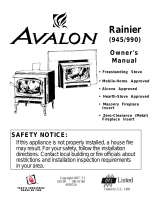
Dimensions
Figure 1
(a) Side, rear, and corner clearances are measured from the stove top.
(b) Rubber-Tipped Leveling Bolts (at each corner).
Emissions
This heater meets the 2020 U.S. EPA’s cord wood emission limits for wood heaters. Tested to EPA Alt-125,
ASTM E3053-17, ASTM 2515-11, CSA B415.1-10 this heater has been shown to deliver heat at
rates ranging from 13,760 to 55,466 BTU/hr and an emission value of 1.71g/h.
Weight: 450 Lbs. (200 Kg)
a
b
19.75"
502mm 5.25"
134mm
2"
51mm 28.25"
718mm
31.5"
801mm

Stove Installation (for qualified installers only) 7
© Travis Industries 8/2/2022 -1431 Rockport
SAFETY NOTICE:
Please read this entire manual before you install and use your new room heater.
Failure to follow instructions may result in property damage, bodily injury, or even
death. Contact local building or fire officials about restrictions and installation
inspection requirements in your area.
Planning the Installation
We suggest that you have an authorized Travis Industries dealer install your stove. If you install the
stove yourself, your authorized dealer should review your installation plans.
Check with local building officials for any permits required for installation of this stove and notify your
insurance company before proceeding with installation.
The location of your wood heater in your home will decide how effectively the heat produced will spread
throughout your house. Attention to the home design with consideration of natural convection and air
circulation should be taken into account when choosing the placement of your heater within the home.
Preparation for Installation
Make sure the baffles and combustor are in place.
Check for damage to the exterior of the stove (dents should be reported, and scratches can be fixed
by applying touch-up paint).
Check the interior of the firebox (replace any cracked firebricks and make sure the baffle and
combustor are in place).
The stove can be lightened by removing the firebricks and baffle (pg. 35) - replace them before
operation.
Packing List
(8) Firebricks (see page 38 for installation instructions)
GreenStart Igniter Parts (steel firebrick, igniter box, and igniter box cover plate)
(1) Fire poker (shipped on pallet)
(1) Wood moisture meter
(1) Pair of gloves
(1) Bypass Tool
(1) Brush (for cleaning combustor)
(1) Temperature Reader (w. installation inst.)

8 Stove Installation (for qualified installers only)
© Travis Industries 8/2/2022 -1431 Rockport
Floor Protection Requirements
Floor protection must extend to the sides, rear, and front of the stove (see “Clearances” below for
minimum floor protection).
Floor protection must be non-combustible and at least .018” (.45mm) thick (26 gauge) – no thermal
protection required (R=0).
Stove Placement Requirements
Clearances may be reduced by methods specified in NFPA 211, listed wall shields, pipe shields, or
other means approved by local building or fire officials.
Stove must be placed so that no combustibles are within, or can swing within 36" (914mm) of the
front of the stove (drapes, doors, etc.)
If the stove is placed in a location where the ceiling height is less than 7' (2.134M), it must follow the
requirements in the section "Alcove Installation Requirements"
Must maintain the clearances to combustibles listed below (drywall, furniture)
The stove requires an air source to operate. Combustion air starvation will result in poor performance
or smoke in the house.
Clearances
The following clearances must be met (see Figure 2 and Figure 3):
Minimum Clearance Single wall
Connector
Reduced
Clearance*
A Sidewall to stovetop 16” (407mm) 16” (407mm)
B Back wall to stovetop 16” (407mm) 10-1/2” (267mm)
C Corner wall to stovetop 9” (229mm) 9” (229mm)
D Connector to sidewall 27-1/8 " (689mm) 26-1/2” (674mm)
E Connector to back wall 18-1/4" (464mm) 12-1/4” (311mm)
F Connector to corner wall 19-1/4” (489mm) 18-3/4” (477mm)
G Floor protection side and back 6” US / 8” Canada
(153mm / 204mm)
6” US / 8” Canada
(153mm / 204mm)
H Floor protection front 16” US / 18” Canada
(407mm / 458mm)
16” US 18” Canada
(407mm / 458mm)
*Reduced clearance installations require one of the chimneys and connectors listed below:
AMERI-TEC model DCC with model HS chimney
DURAVENT model DVL with DURATEC or DURA-PLUS chimney
GSW Super Chimney Twenty-One connected directly to appliance
I.C.C. Excel (2100-2 Can.) (103-HT USA) chimney with ULTRABlack connector
METALFAB model DW connector with TG chimney
OLIVER MACLEOD PROVENT model PV connector with model 3103 chimney
SECURITY model DP or DL connector with SECURITY model ASHT or S2100 chimney
SELKIRK METALBESTOS model DS connector with model SSII chimney
OLYMPIA VENTIS with Ventis double wall black stove pipe
Standard Masonry Chimney with any one of the above listed connectors
NOTE: Reduced clearance connectors may not connect to the flue collar – an appliance adapter may be required.
NOTE: Standard residential installations with reduced clearance connector may use the clearance
determined by the manufacturer of the connector for the connector to wall clearance or the clearance
listed in this manual. Offsets must be used to maintain the stove to wall clearance.

Stove Installation (for qualified installers only) 9
© Travis Industries 8/2/2022 -1431 Rockport
Top View -
Straight Installation
Figure 2
Top View -
Corner Installation
Figure 3
Measure rear and side clearances from
the nearest edge of the stove top.
Floor Protection
Measure front clearances from the
face of the stove (door opening).
Clearance A
NOTE: vent diameter may vary
depending on brand and model.
Clearance E
Clearance B
Back Wall
Side Wall
Clearance D
Typical Flue Center
Singlewall 21.25" (540mm)
Reduced Clearance 15.75" (401mm)
Typical Flue Center 30.125" 766mm
5.25"
134mm
28.25" 718mm
2"
51mm
19.75"
502mm
Clearance G
Clearance H
Clearance G
2"
51mm
Measure rear and side clearances from
the nearest edge of the stove top.
Floor Protection
Measure front clearances from the
face of the stove (door opening).
NOTE: vent diameter may vary
depending on brand and model.
Corner Wall
Corner Wall
Clearance C
Clearance F
Typical Flue Center
22.5" 572mm
Clearance G
Clearance H
Clearance G
5.25"
134mm
28.25" 718mm
19.75"
502mm

10 Stove Installation (for qualified installers only)
© Travis Industries 8/2/2022 -1431 Rockport
Chimney Connector Requirements
Chimney connector is required from the flue collar of the stove to the factory-built chimney or
masonry chimney.
The chimney connector must be 6” (152mm) diameter and a minimum 24 gauge black steel, or one of
the reduced-clearance connectors listed on page 8.
NOTE: Aluminum or galvanized steel is not allowed – these materials cannot withstand the flue
temperatures and may give off toxic fumes when heated.
NOTE: Standard residential installations may use single-wall connector (Mobile-Homes may not).
The chimney connector may not pass through a ceiling, attic, roof, closet, or any other concealed
space (use listed UL 103 HT chimney – see “Chimney Requirements for details). DO NOT USE
CONNECTOR PIPE AS CHIMNEY.
IN CANADA: Where passage through a wall or partition of combustible construction is desired, the
installation shall conform to CAN/CSA-B365, Installation Code for Solid-Fuel-Burning Appliances and
Equipment.
The chimney connector should be as short and direct as possible. No more than 180o of elbows (two 90o
elbows, or two 45o & one 90o elbow, etc.) may be used for the entire system (connector and chimney).
Horizontal runs should slope upwards 1/4” (6mm) per foot and be a maximum 36” (914mm) long.
The chimney connector must be installed with the crimped end pointing downwards. This prevents
creosote from leaking to the exterior of the pipe.
The chimney connector must be fastened to the stove and each adjoining section (and chimney).
Standard residential installations with reduced clearance connector may use the clearance determined
by the manufacturer of the connector for the connector to wall clearance or the clearance listed in this
manual. Offsets must be used to maintain the stove-to-wall clearance. Mobile homes must use the
clearances listed in this manual under "Additional Requirements for Mobile Home Installations".

Stove Installation (for qualified installers only) 11
© Travis Industries 8/2/2022 -1431 Rockport
Chimney Requirements
DO NOT CONNECT THIS UNIT TO A CHIMNEY FLUE SERVING ANOTHER APPLIANCE.
DO NOT CONNECT TO OR USE IN CONJUNCTION WITH ANY AIR DISTRIBUTION DUCTWORK
UNLESS SPECIFICALLY APPROVED FOR SUCH INSTALLATIONS
IN CANADA: This appliance must be connected to a factory-built chimney conforming to CAN/ULC-
S629, Standard for 650°C Factory-Built Chimneys.
UL 103 HT Chimney must be used from the first ceiling or floor or wall penetration to the chimney
cap.
Use 6" (152mm) diameter type UL 103 HT chimney from one manufacturer (do not mix brands) or
code approved masonry chimney with a flue liner.
Chimney must be fastened to each adjoining section.
Follow the chimney manufacturer's clearances and requirements.
Use the chimney manufacturer's fire stops, attic guards, roof supports, and flashings when passing
through a ceiling and roof (see “b” and “d” below).
No more than 180o of elbows (two 90o elbows, or two 45o & one 90o elbow, etc.) may be used for the
entire system (connector and chimney).
NOTE: Additional elbows may be allowed if draft is sufficient. Whenever elbows are used the draft is
adversely affected. Additional chimney height may be required to boost draft.
(a) Min. System Height 15’ (4.5M)
Max. System Height 33’ (10.058M)
(b) Roof Penetration and Termination (see
chimney manufacturer’s requirements)
(c) Chimney Sections
(d) Ceiling Penetration (see chimney
manufacturer’s requirements)
(e) Minimum air space to combustibles (see
chimney manufacturer’s requirements –
typically 2” / 51mm)
(f) Connector – see “Chimney Connector” on the
previous page.
Figure 4
Drafting Performance
Draft is the force which moves air from the appliance up through the chimney. The amount of draft in your
chimney depends on the length of the chimney, local geography, nearby obstructions and other factors. Too
much draft may cause excessive temperatures in the appliance and may damage the heater. Inadequate draft
may cause backpuffing into the room and `plugging' of the chimney. Inadequate draft will cause the appliance
to leak smoke into the room through appliance and chimney connector joints. An uncontrollable burn or
excessive temperature indicates excessive draft.
}
}
}
a
b
c
de
f
f
b

12 Stove Installation
(for qualified installers only)
© Travis Industries 8/2/2022 -1431 Rockport
Chimney Termination Requirements
Must have an approved cap (to prevent water from entering)
Must not be located where it will become plugged by snow or other material
Must terminate at least 3' (914mm) above the roof and at least 2' (610mm) above any portion of the
roof within 10' (3.048M) (see Figure 5)
Figure 5
Outside Air Requirements
Required for mobile homes and in certain localities (check with local building official)
Must not be drawn from an enclosed space (garage, unventilated crawl space)
Requires a 3” duct that attaches to the bottom of the stove (see “a” and “b” below).
Outside air duct must have a rodent screen and rain hood (“c”).
The Travis Industries Outside Air Kit (sku 99200139) includes all the above components.
Figure 6
S
lanted Roofs
F
lat Roofs
Chimney must
extend 3'
above the roof
Chimney must extend 2'
above any portion of the roof
within 10' of the chimney
Chimney must
extend 3'
above the roof
Chimney must extend 2'
above any portion of the roof
within 10' of the chimney
a
b
c

Stove Installation (for qualified installers only) 13
© Travis Industries 8/2/2022 -1431 Rockport
Alcove Installation Requirements
Whenever the stove is placed in a location where the ceiling height is less than 7' (2.134M) tall, it is
considered an alcove installation. Because of the reduced height, the special installation requirements
listed below must be met.
Chimney connector and chimney must be one of the following types:
AMERI-TEC model DCC with model HS chimney
DURAVENT model DVL with DURATEC or DURA-PLUS chimney
GSW Super Chimney Twenty-One connected directly to appliance
I.C.C. Excel (2100-2 Can.) (103-HT USA) chimney with ULTRABlack connector
METALFAB model DW connector with TG chimney
OLIVER MACLEOD PROVENT model PV connector with model 3103 chimney
SECURITY model DP or DL connector with SECURITY model ASHT or S2100 chimney
SELKIRK METALBESTOS model DS connector with model SSII chimney
Standard Masonry Chimney with any one of the above listed connectors
NOTE: Reduced clearance connectors may not connect to the flue collar – an appliance adapter may be required.
Alcoves are classified as combustible or non-combustible. Non-combustible alcoves must have walls
and a ceiling that are 3 1/2" (89mm) thick of a non-combustible material (brick, stone, or concrete -
see Figure 7). This non-combustible material must be spaced and ventilated at least 1" (25mm) off of
all combustible materials (walls, ceiling, etc.) to allow air to move around the non-combustible walls
and ceiling. All other alcoves are considered combustible. The clearances below must be met:
Minimum Clearance
(See Figure 7 below)
Combustible
Alcove
Non-Combustible
Alcove
A
Sidewall to stove 16" 6"
B Back wall to stove 10-1/2" 6-3/4"(with fan)
4”
(
without fan
)
D Connector to sidewall 26-1/2" 16-1/2"
E Connector to back wall 12-1/4" 8-3/8”(with fan)
5-5/8”
(
without fan
)
G Maximum depth of alcove 48" 48"
H Minimum width of alcove 60-1/4” 40-1/4”
J Minimum hei
g
ht of alcove 84” 6" above stove top
Non-Combustible Alcove
(a) Non-Combustible (brick)
(b) Air Space with non-combustible
reinforcement
(c) Combustible material
Figure 7
Min. 3 1/2"
(89mm)
Min. 1"
(25mm)
a
c
b
a
b
de
h
j
g

14 Stove Installation (for qualified installers only)
© Travis Industries 8/2/2022 -1431 Rockport
Mobile Home Requirements
Outside air must be installed - see "Outside Air Requirements" on page 12
Chimney connector and chimney must be one of the following types:
AMERI-TEC model DCC with model HS chimney
DURAVENT model DVL with DURATEC or DURA-PLUS chimney
GSW Super Chimney Twenty-One connected directly to appliance
I.C.C. Excel (2100-2 Can.) (103-HT USA) chimney with ULTRABlack connector
METALFAB model DW connector with TG chimney
OLIVER MACLEOD PROVENT model PV connector with model 3103 chimney
SECURITY model DP or DL connector with SECURITY model ASHT or S2100 chimney
SELKIRK METALBESTOS model DS connector with model SSII chimney
Standard Masonry Chimney with any one of the above listed connectors
NOTE: Reduced clearance connectors may not connect to the flue collar – an appliance adapter may be required.
Stove placement must maintain the following clearances to combustibles (drywall, furniture, etc.)
Figure 8
Minimum Clearance
(See the illustration above)
Reduced Clearance
Connector
A
Sidewall to stovetop 16”
(
406mm
)
B Back wall to stovetop 10-1/2”
(
267mm
)
C Corner wall to stove 9”
(
229mm
)
D Connector to sidewall 26-1/2”
(
673mm
)
E Connector to back wall 12-1/4”
(
311mm
)
F Connector to corner wall 18-3/4”
(
476mm
)
If using offsets, use the connector clearance listed in
Figure 9, not the connector manufacturer's
clearance.
The appliance must be secured to the floor (consult
your building official). Leg clips are available from
Travis Industries (sku 98900509).
Mobile home installations require a spark arrester at
the chimney termination. Follow the chimney
manufacturer’s instructions for maintaining a proper
moisture barrier at the external chimney penetration.
The appliance must be grounded to the chassis of the
mobile home (consult your building official).
WARNING: DO NOT INSTALL IN SLEEPING ROOM.
CAUTION: THE STRUCTURAL INTEGRITY OF THE
MOBILE HOME FLOOR, WALL, AND CEILING/ROOF
MUST BE MAINTAINED.
Figure 9
A
B
F
C
Measure clearances from the
nearest edge of the stove top.
D
EC
12” Min.
Connector Clearance
(as outlined above)
Stove Clearance
(as outlined above)

Stove Installation (for qualified installers only) 15
© Travis Industries 8/2/2022 -1431 Rockport
Standard Ceiling
with a Factory-
Built Chimney
Figure 10
Cathedral Ceiling
with a Factory-
Built Chimney
Figure 11
Chimney Cap
(See the section "Chimney
Termination Requirements"
for more details)
Chimney Sections
Minimum Air Space to
Combustibles (See
Chimney Manufacturer's
Instructions - usually 2")
Chimney Connector Sections
Follow the chimney
manufacturer's instructions
and clearances for roof
penetrations. A storm collar
and flashing are required
(some require a radiation
shield).
}
}
Minimum 15'
Maximum 33'
Stove Clearances
(See the section "Stove
Placement Requirements"
for more details)
Floor Protection
(See the section "Floor
Protection Requirements"
for more details)
Follow the chimney
manufacturer's instructions
and clearances for floor
penetrations. A ceiling
support is required, an attic
insulation shield is required
where insulation is present.
Insulation
Chimney Cap
(See the section "Chimney
Termination Requirements"
for more details)
Chimney Sections
Minimum Air Space to
Combustibles (See Chimney
Manufacturer's Instructions -
usually 2")
Follow the chimney
manufacturer's instructions
and clearances for roof
penetrations. A storm
collar, flashing, and
cathedral-style chimney
support are required
(some require a radiation
shield).
}
Minimum 15'
Maximum 33'
Stove Clearances
(See the section "Stove
Placement Requirements"
for more details)
Floor Protection
(See the section "Floor
Protection Requirements"
for more details)
Chimney
Connector
Sections

16 Stove Installation (for qualified installers only)
© Travis Industries 8/2/2022 -1431 Rockport
Exterior Factory-Built Chimney
A vertical rise of 84” of chimney connector is required, measured from the floor, before entering a Class
‘A’ wall penetration. For those wishing to pass the chimney through the lower wall, a NFPA 211 wall
pass-through may be used (if approved by local building codes).
Floor Protection Under Connector Pipe.
When using any horizontal connector, the floor protection must extend below the connector pipe and 2” in
all directions (until it contacts the wall).
Wall Penetrations Under 84”
In cases where the chimney connector must be passed through a combustible wall or partition under 84”,
the following NFPA 211 method may be used if local building codes permit. Check with local authorities
before installation to insure all necessary requirements have been met. Figure 12 details a wall pass-
through based on the NFPA 211 standard. After the pass-through, Class A Chimney may be used in
accordance with the chimney installation instructions.
Figure 12
Wall Penetrations 84” or Greater
A vertical rise of 84” of chimney connector is required, measured from the floor, before entering a Class
‘A’ chimney wall penetration (see Figure 13 below). Note that the measurement is to the centerline of the
flue when it makes a 90 degree bend. Follow the clearances specified by the manufacturer of the double-
wall connector (or 18” if using single-wall connector).
Figure 13
NFPA 211 Wall Pass-Through
(see NFPA 211 for a full description)
12 Min.
12 Min.
Combustible Materials
Brick
Fire Clay Thimble
Follow the chimney manufacturer's
instructions and clearances for wall
penetrations. A wall radiation shield
(thimble) is required.
Follow Clearance Determined by
Doublewall Connector Manufacturer
(18" if using single-wall connector)
Chimney
Connector
Sections
Follow
Clearances
Listed in the
Manual
}
UL 103 HT
Chimney System
Minimum 84"
Floor protection must extend to the
back wall and 2" to each side of the
connector

Stove Installation (for qualified installers only) 17
© Travis Industries 8/2/2022 -1431 Rockport
Hearth Stove
Installation
NOTE:
This type of installation
requires a full reline
(positive connection).
Interior or Exterior
Masonry Chimney
NOT ALLOWED IN CANADA
UNLESS FULL RELINE IS
USED>.
NOTE:
This type of installation
requires a UBC approved
masonry connector or other
method approved by the NFPA
211 Standard. See Chimney
Connector Requirements on
page 10 for further details.
WARNING:
We strongly recommend a full
reline (positive connection)
when venting through a
masonry chimney. The
Rockport is equipped with a
combustor and may draft
poorly without a full reline. We
also recommend that a
minimum 3’ chimney be added
to the minimum system height
for every 1’ of horizontal run.
Remove damper
or wire it open
Airtight Insulated
Clean-Out
Min. 18"
Combustible
Mantle
NOTE: The entire fireplace and
chimney must be clean, undamaged,
and meet all local building codes
(UBC, etc.). Damage must be
repaired prior to installation. The
chimney must be 15' to 33' tall.
Floor Protection
(See the section
"Floor Protection
Requirements"
for more details)
See the section
"Stove Placement
Requirements" for
minimum clearances
required.
The liner must be
stainless steel connector
or flexible vent. Follow
the liner manufacturer's
instructions for installation
and support.
Cap and flashing
prevents water from
entering
Make sure the
clean-out seals in
place.
Clay Liner
See the section "Stove
Placement Requirements" for
minimum clearances required.
Min. 18"
clearance
to ceiling This type of
installation requires
a UBC approved
masonry connector
or other method
approved by the
NFPA 211 standard.
Chimney connector sections
NOTE: The chimney must
have a clay tile liner. If it does
not, the installation must use a
full reline (positive
connection). The entire
fireplace and chimney must
be clean, undamaged, and
meet all local building codes
(UBC, etc.). Damage must be
repaired prior to installation.
The chimney must be 15' to
33' tall.
See the section
"Floor Protection
Requirements"
Full Reline

18 Operating Your Appliance
© Travis Industries 8/2/2022 -1431 Rockport
Safety Notice
If this appliance is not properly installed, a house fire may result. For your safety, follow the installation
directions. Contact local building or fire officials about restrictions and installation inspection
requirements in your area.
The air control may become hot during operation - use gloves or a tool to prevent burns.
Use gloves when reloading wood.
Read and follow all of the warnings on pages 4 and 5 of this manual.
Do not operate this stove with the ash pan open. A fire hazard will result.
Before Your First Fire
Verify the Installation:
Before starting the stove, verify that the stove is properly installed and all of the requirements in this
manual have been followed.
Keep all flammable materials 36" (914mm) away from the front of the stove (drapes, furniture, clothing, etc.).
Curing the Paint
Follow the steps below to cure the paint (first fire):
a) Open doors and windows in the room to ventilate the heater during the
curing process.
b) Vacate the room. The fumes from the initial heating process are non-toxic
but may be unpleasant.
c) Slowly bring the heater to a medium burn (400°F/204°C) for 45 minutes.
Then increase the burn temperature to a hot burn (600°F/315°C) for an
additional 45 minutes. This will cure the paint.
Door Gasket - The door gasket can adhere to the paint on the front of the
heater. To prevent this, carefully open and close the door a few times during
the paint curing process.
Carbon Monoxide (CO) Emissions
Smoke from wood heaters contain CO. This gas is an indication of incomplete combustion and is
detrimental to the environment and to your health. The more visible the smoke, the higher the CO levels.
Burning dry wood is the most significant step you can take to reduce CO emissions. It is also important to
understand the combustion process so you can burn your heater efficiently. Read the manual thoroughly
so that you can operate your heater in the most efficient and clean manner possible.
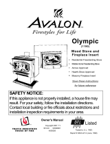
Over-Firing the Stove
DO NOT OVERFIRE THIS HEATER: Attempts to achieve heat output rates that exceed heater design
specifications can result in permanent damage to the heater.
This stove was designed to operate at a high temperature. But due to differences
in vent configuration, fuel, and draft, this appliance can be operated at an excessive
temperature. If the stove top or other area starts to glow red, you are over-firing the
stove. Shut the air control down to low and allow the stove to cool before
proceeding.
Over-firing may lead to damage. If you are uncertain of over-firing conditions, we
suggest placing a stove thermometer (e.g. Rutland® Model 710) directly in front of
the flue outlet on the stovetop (see photo below) temperatures exceeding 700°
are
g
enerall
y
considered over-firin
g
and will void the warrant
y
.
2 to 4 hours
IDB1135

Operating Your Appliance 19
© Travis Industries 8/2/2022 -1431 Rockport
Opening the Door
The door becomes hot during use. Use a glove to open the door if the handle is hot.
Do not operate this stove with the door open. A fire hazard will result.
To prevent smoke from entering the room, open the air control and bypass (see instructions below)
before opening the door. You can also open the door a small amount and let air enter the firebox to
equalize the pressure, and then open the door fully.
Bypass Operation
T
he bypass control becomes hot during operation - use gloves or a tool to prevent burns.
The bypass controls the flow of smoke inside the heater. When pulled out, smoke goes directly up the
flue, creating more draft. When pushed in, the smoke goes around the baffle, utilizing the secondary
combustion and making the heater more efficient.
When re-loading, pull the bypass out.
During normal operation, push the bypass in.
Bypass Pulled Out
Used for starting and re-loading
Bypass Pushed In
Used for normal operation
Use the included pull
tool to operate the
bypass rod

20 Operating Your Appliance
© Travis Industries 8/2/2022 -1431 Rockport
Maintaining Combustor Burn-Off
Warning:
The bypass control becomes hot
during operation - use gloves or a
tool to prevent burns.
This stove uses a combustor to
increase heat transfer to the room
and reduce emissions.
Follow the directions below to utilize the combustor to its fullest potential.
• Keep the by-pass open (pulled out) until the stove becomes hot (approximately 15 to 30 minutes).
• Close the by-pass (push in) when the stove is hot.
• Keep the by-pass closed (pushed in) while the stove is operating, except when re-loading.
How to Check if your Combustor is Working
A combustor temperature probe is included with the
fireplace to monitor the combustor. After the bypass
is engaged, the combustor temperature should rise,
showing combustor operation. Combustor
temperatures over 500° F (260° C) indicate the
combustor is working and igniting unburnt fuel.
The combustor can also be viewed through the glass
from below. You will notice the combustor glowing
red when the combustor is working effectively.
The catalytic combustor
takes dirty smoke and turns it
into extra heat and cleaner
emissions.
NOTE: If the combustor is engaged
(bypass closed) when the fireplace
is still cool, it will not work, leading
to dirty smoke, no extra heat, and a
dirtier combustor.
Bypass Pulled Out
With the by-pass open (pulled out), the
smoke passes through the by-pass and does
not go through the combustor.
Bypass Pushed In
With the by-pass closed (pushed in), the
smoke passes through the combustor.
Use the included pull tool
to operate the bypass rod
The catalytic temperature probe wire is located on the left side.
Attach it to the meter (see photo) and place it near the stove.
Press this
ON/HOLD button
to view the
temperature.
/